EP0196257B1 - Ölradiator enthaltender Wasserkasten für Kraftfahrzeugwärmetauscher - Google Patents
Ölradiator enthaltender Wasserkasten für Kraftfahrzeugwärmetauscher Download PDFInfo
- Publication number
- EP0196257B1 EP0196257B1 EP86400575A EP86400575A EP0196257B1 EP 0196257 B1 EP0196257 B1 EP 0196257B1 EP 86400575 A EP86400575 A EP 86400575A EP 86400575 A EP86400575 A EP 86400575A EP 0196257 B1 EP0196257 B1 EP 0196257B1
- Authority
- EP
- European Patent Office
- Prior art keywords
- water header
- water box
- oil radiator
- radiator
- oil
- Prior art date
- Legal status (The legal status is an assumption and is not a legal conclusion. Google has not performed a legal analysis and makes no representation as to the accuracy of the status listed.)
- Expired
Links
Images

Classifications
-
- F—MECHANICAL ENGINEERING; LIGHTING; HEATING; WEAPONS; BLASTING
- F28—HEAT EXCHANGE IN GENERAL
- F28F—DETAILS OF HEAT-EXCHANGE AND HEAT-TRANSFER APPARATUS, OF GENERAL APPLICATION
- F28F9/00—Casings; Header boxes; Auxiliary supports for elements; Auxiliary members within casings
- F28F9/02—Header boxes; End plates
- F28F9/0234—Header boxes; End plates having a second heat exchanger disposed there within, e.g. oil cooler
-
- F—MECHANICAL ENGINEERING; LIGHTING; HEATING; WEAPONS; BLASTING
- F01—MACHINES OR ENGINES IN GENERAL; ENGINE PLANTS IN GENERAL; STEAM ENGINES
- F01P—COOLING OF MACHINES OR ENGINES IN GENERAL; COOLING OF INTERNAL-COMBUSTION ENGINES
- F01P11/00—Component parts, details, or accessories not provided for in, or of interest apart from, groups F01P1/00 - F01P9/00
- F01P11/08—Arrangements of lubricant coolers
-
- Y—GENERAL TAGGING OF NEW TECHNOLOGICAL DEVELOPMENTS; GENERAL TAGGING OF CROSS-SECTIONAL TECHNOLOGIES SPANNING OVER SEVERAL SECTIONS OF THE IPC; TECHNICAL SUBJECTS COVERED BY FORMER USPC CROSS-REFERENCE ART COLLECTIONS [XRACs] AND DIGESTS
- Y10—TECHNICAL SUBJECTS COVERED BY FORMER USPC
- Y10S—TECHNICAL SUBJECTS COVERED BY FORMER USPC CROSS-REFERENCE ART COLLECTIONS [XRACs] AND DIGESTS
- Y10S165/00—Heat exchange
- Y10S165/916—Oil cooler
Definitions
- the invention relates to a water box of a heat exchanger for a motor vehicle, this water box containing an oil radiator, to allow, essentially, to cool by the liquid circulating in the exchanger the oil which circulates in the radiator.
- the oil radiator is placed in the water box before mounting it on the end of a bundle of tubes or a heat exchanger body, the radiator d oil being introduced into the water box through the open face thereof which will cap the end of the body or bundle of tubes of the exchanger.
- the oil radiator comprises two pipes connecting to the lubricating oil circuit of the engine and / or the gearbox, these two pipes being sealed and fixed in two holes in the side wall of the water box, which have a diameter corresponding substantially to the external diameter of the pipes, for sealing reasons.
- the water box must have a width at least substantially equal to the total size of the oil radiator in the same dimension, that is to say in general to the width of the radiator increased by the length of the pipes.
- the water box must therefore have a relatively large width, which is much greater than the thickness, or corresponding dimension, of the bundles of tubes of current exchangers and which is therefore disproportionate to this dimension of the bundle.
- a water box of a heat exchanger comprising an oil radiator, provided in advance with two oil inlet and outlet pipes. which pass through two openings in a side wall of the water box and through which the oil radiator is held and fixed in the water box.
- the openings of the water box are closed respectively by two fixing members, namely sleeves made of elastomeric material, each of which comprises an orifice for passage of the pipes.
- the oil radiator is placed inside the water box by forcibly introducing the pipes in the two corresponding sleeves, these deform to adapt tightly to the pipes and thus ensure sealing.
- the internal width of the water box is substantially equal, if not greater, to the overall width of the oil radiator.
- the object of the invention is in particular to avoid these drawbacks.
- It relates to a water box for a heat exchanger, which has the same dimensions and the same overall dimensions as the usual water boxes and which can however contain the same oil radiator, provided in advance with pipes, as the wide water boxes of the prior art, being mounted by the open face of the water box;
- the invention therefore provides, for this purpose, a water box of a heat exchanger for motor vehicles, comprising an oil radiator, provided in advance with two oil inlet and outlet pipes which pass through sealing two openings in a side wall of the water box and through which the oil cooler is held and fixed in the water box, the openings having a dimension greater than the outside diameter of the pipes and being closed respectively by two fixing members each of which comprises an orifice for the passage of a tube.
- each of the openings is limited by a flat peripheral rim and in that each of the fixing members is an attached plate external to the water box which, after installation of the radiator of oil in the water box, is threaded on one end of tubing, with interposition of a seal between the tubing and the insert plate, and which is then fixed by its internal face on the peripheral rim of the corresponding opening.
- Each opening of the side wall of the water box has a dimension or a diameter allowing the deflection of a tube of the oil radiator when the latter is introduced into the water box through the open face of the latter.
- each tube of the oil radiator comprises an annular flange which is applied to the internal face of the aforementioned plate, and a part with an external thread, which extends on the other side of the plate and receives a tightening nut. this plate on the annular rim.
- FIG. 1 representing a water box of the prior art, containing an oil radiator.
- the known water box designated by the reference 10, is conventionally mounted at one end of a bundle of tubes 12, by means of a manifold or tube plate 14, and contains an oil radiator 16 of the type classic tubular.
- This radiator 16 also shown in FIG. 3, comprises two coaxial cylindrical walls 18 and 20 with circular sections, connected with sealing at their ends, and two pipes 22 arranged in the vicinity of these axial ends and opening into the annular space comprised between the cylindrical walls 18 and 20.
- Each pipe 22 is oriented perpendicular to the axis 24 of the radiator 16 and comprises a flange or an annular flange 26 in the immediate vicinity of the external cylindrical wall 18 of the radiator, and a cylindrical end portion with thread outside 28 intended to receive a nut 30.
- the water box 10 comprises a side wall 32 pierced by two orifices in which the cylindrical end portions 28 of the pipes 22 of the radiator are engaged.
- the annular flanges or flanges 26 of the pipes 22 are applied to the internal face of the side wall 32 of the water box with the interposition of a seal, and the nuts 30 screwed onto the ends 28 of the pipes are tightened on the external face of the side wall 32, so that the oil radiator 16 is thus maintained and fixed on the side wall 32 of the water box 10.
- the oil radiator 16 is introduced into the water box through the open face of the latter, which covers the end of the bundle of tubes 12 and includes a peripheral rim (not visible in FIG. 1) by which it can be fixed to the manifold 14.
- the internal width L of the water box 10 must be substantially equal to the size 1 of the radiator 16 in width, constituted by the outside diameter of its outer cylindrical wall 18 and the length of the pipes. 22.
- the width L of the water box 10 is thus much greater than the corresponding dimension d of the bundle of tubes 12 and is disproportionate with respect thereto.
- the manifold 14 and the seals or seals cooperating with the manifold 14 and with the peripheral rim of the open face of the water box 10 necessarily have a width dimension corresponding to that of the water box 10. It is therefore leads in the prior art, when it is desired to house an oil radiator 16 inside a water box 10, to use a water box, a manifold and seals of a special type, which is disadvantageous from an economic point of view.
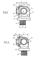
- This water box 34 is mounted at the end of the bundle of tubes 12 by a conventional manifold 36, identical to that which would be used for fixing an ordinary water box not containing the oil radiator 16.
- the water box 34 according to the invention has an internal width L ′ equal to that of a usual water box corresponding to the dimension d of the bundle of tubes 12 and not containing an oil radiator.
- the side wall 48 of the water box 34 which is crossed by the pipes of the oil radiator, comprises two circular openings 52, one of which is shown in the right part of FIG. 4, each opening 52 being limited by a planar annular peripheral rim 54 and having a sufficient dimension to allow the deflection of a pipe 22 of the radiator 16 when the latter is introduced into the water box 34 through the open face 56 thereof, the pipes 22 then being oriented vertically upwards, then inclined obliquely in the direction of the openings 52 as the radiator 16 is introduced into the water box, finally in the arrangement shown in FIG. 2.
- Each opening 52 of the water box is intended to be closed by an attached plate 58, of circular shape, the external diameter of which is substantially equal to that of the peripheral rim 54 of the opening 52.
- Each circular plate 58 is formed with a orifice for the passage of the threaded end portion of a pipe 22 of the oil radiator.
- the plates 58 are threaded onto the ends of the pipes 22 with the interposition of a seal.
- the nuts 30 are screwed onto the ends of the pipes and tighten the plates 58 against the annular flanges or flanges 26 of the pipes.
- the plates 58 are fixed at their periphery to the annular edges 54 of the openings 52, by ultrasonic welding, by gluing or any other suitable means.
- the flanges or flanges 26 of the pipes have a diameter smaller than that of the openings 52, which makes it possible to easily place the oil radiator in a water box of normal width.
- the fact that the oil radiator has a generally cylindrical shape also facilitates this arrangement.
- the openings 52 of the wall of the water box may have a non-circular shape and that they may extend over the top wall of the water box.
- the largest transverse dimension of the body of the oil radiator is less than the width of the open face of the water box so that this radiator can be disposed without difficulty in the water box.
Landscapes
- Engineering & Computer Science (AREA)
- Mechanical Engineering (AREA)
- General Engineering & Computer Science (AREA)
- Physics & Mathematics (AREA)
- Thermal Sciences (AREA)
- Chemical & Material Sciences (AREA)
- Combustion & Propulsion (AREA)
- Heat-Exchange Devices With Radiators And Conduit Assemblies (AREA)
Claims (8)
Applications Claiming Priority (2)
| Application Number | Priority Date | Filing Date | Title |
|---|---|---|---|
| FR8504214A FR2579309B1 (fr) | 1985-03-21 | 1985-03-21 | Boite a eau d'un echangeur de chaleur pour vehicule automobile, contenant un radiateur d'huile |
| FR8504214 | 1985-03-21 |
Publications (2)
| Publication Number | Publication Date |
|---|---|
| EP0196257A1 EP0196257A1 (de) | 1986-10-01 |
| EP0196257B1 true EP0196257B1 (de) | 1988-07-27 |
Family
ID=9317434
Family Applications (1)
| Application Number | Title | Priority Date | Filing Date |
|---|---|---|---|
| EP86400575A Expired EP0196257B1 (de) | 1985-03-21 | 1986-03-18 | Ölradiator enthaltender Wasserkasten für Kraftfahrzeugwärmetauscher |
Country Status (5)
| Country | Link |
|---|---|
| US (1) | US4665972A (de) |
| EP (1) | EP0196257B1 (de) |
| DE (1) | DE3660440D1 (de) |
| ES (1) | ES296576Y (de) |
| FR (1) | FR2579309B1 (de) |
Families Citing this family (16)
| Publication number | Priority date | Publication date | Assignee | Title |
|---|---|---|---|---|
| SE462059B (sv) * | 1986-12-19 | 1990-04-30 | Blackstone Sweden | Vaermevaexlare med platta roer, vilka roer bildas av tvaa halvor med oeverlappande flaensar |
| FR2614978B1 (fr) * | 1987-05-06 | 1989-12-08 | Valeo | Dispositif de boite a eau pour un radiateur de refroidissement pour un vehicule automobile, contenant un echangeur d'huile |
| FR2626662B1 (fr) * | 1988-02-02 | 1991-08-16 | Hutchinson Sa | Dispositif d'assemblage pour un ensemble echangeur de chaleur/raccord tubulaire |
| FR2626663B1 (fr) * | 1988-02-02 | 1991-10-31 | Hutchinson Sa | Dispositif d'assemblage pour un ensemble echangeur de chaleur/raccord tubulaire |
| FR2665523B1 (fr) * | 1990-07-31 | 1992-10-16 | Valeo Thermique Moteur Sa | Boite a eau d'un echangeur de chaleur principal, en particulier pour vehicules automobiles, contenant un echangeur de chaleur secondaire. |
| FR2665524B1 (fr) * | 1990-07-31 | 1992-10-16 | Valeo Thermique Moteur Sa | Boite a eau d'un echangeur de chaleur principal, notamment pour vehicules automobiles, contenant un echangeur de chaleur secondaire. |
| FR2722562B1 (fr) * | 1994-07-15 | 1996-09-06 | Valeo Thermique Moteur Sa | Boite a eau d'echangeur de chaleur contenant un radiateur d'huile |
| EP0846931B1 (de) * | 1996-12-03 | 2002-07-03 | Calsonic Kansei Corporation | Befestigungsvorrichtung für Ölkühler und Verfahren zur Befestigung eines Ölkühlers |
| DE19711259A1 (de) * | 1997-03-18 | 1998-10-15 | Behr Gmbh & Co | Getriebeölkühler |
| US20040173341A1 (en) * | 2002-04-25 | 2004-09-09 | George Moser | Oil cooler and production method |
| US20040089439A1 (en) * | 2002-11-07 | 2004-05-13 | Treverton Andrew Clare | Tube-to-tube heat exchanger assembly |
| DE10348699A1 (de) * | 2003-10-16 | 2005-05-12 | Behr Gmbh & Co Kg | Kühlmittelkühler eines Kraftfahrzeuges |
| US7428833B2 (en) * | 2004-12-22 | 2008-09-30 | Peak Recreational Products, Llc | Vehicle mountable personal property lock assembly |
| US7188664B2 (en) * | 2005-04-21 | 2007-03-13 | Delphi Technologies, Inc. | Aluminum radiator tank with oil cooler clinch fitting |
| JP4722577B2 (ja) * | 2005-06-21 | 2011-07-13 | カルソニックカンセイ株式会社 | オイルクーラ |
| WO2014121390A1 (en) | 2013-02-08 | 2014-08-14 | Dana Canada Corporation | Heat exchanger with annular inlet/outlet fitting |
Family Cites Families (14)
| Publication number | Priority date | Publication date | Assignee | Title |
|---|---|---|---|---|
| DE1224039B (de) * | 1964-02-06 | 1966-09-01 | Bayer Ag | Unter Ausschluss von Wasser lagerfaehige, plastische Organopolysiloxanformmassen |
| FR1476550A (fr) * | 1965-07-07 | 1967-04-14 | Thomson Houston Comp Francaise | Perfectionnements aux échangeurs de chaleur à ébullition de surface |
| FR2031669A5 (de) * | 1969-02-03 | 1970-11-20 | Chausson Usines Sa | |
| FR2306421A1 (fr) * | 1975-04-02 | 1976-10-29 | Ferodo Sa | Perfectionnements aux appareils de refroidissement de liquides |
| FR2361619A1 (fr) * | 1976-08-10 | 1978-03-10 | Uop Inc | Refroidisseur d'huile pour automobile |
| FR2389306A7 (fr) * | 1977-04-30 | 1978-11-24 | Sueddeutsche Kuehler Behr | Echangeur de chaleur dispose dans un recipient qui contient un fluide de refroidissement, en particulier radiateur a huile |
| US4227570A (en) * | 1979-10-01 | 1980-10-14 | Caterpillar Tractor Co. | Heat exchange structure |
| DE3027435A1 (de) * | 1980-07-19 | 1982-02-18 | Süddeutsche Kühlerfabrik Julius Fr. Behr GmbH & Co KG, 7000 Stuttgart | Waermetauscher mit mehreren doppelrohren |
| DE3236620A1 (de) * | 1981-10-05 | 1983-04-21 | Hydro-Flex Corp., 66618 Topeka, Kan. | Temperatursteuerung fuer ein getriebefluid |
| DE3142028A1 (de) * | 1981-10-23 | 1983-05-05 | Süddeutsche Kühlerfabrik Julius Fr. Behr GmbH & Co KG, 7000 Stuttgart | Oelkuehler |
| FR2521277B1 (fr) * | 1982-02-08 | 1987-07-24 | Valeo | Echangeur de chaleur, en particulier pour un circuit de refroidissement de moteur a combustion interne |
| GB2122706B (en) * | 1982-06-19 | 1986-08-13 | Unipart Group Ltd | Heat exchanger coupling |
| FR2548770A1 (fr) * | 1983-07-04 | 1985-01-11 | Chausson Usines Sa | Echangeur de chaleur a deux fluides liquides |
| FR2549593B1 (fr) * | 1983-07-22 | 1987-04-10 | Chausson Usines Sa | Boite a eau d'echangeur de chaleur contenant un echangeur de chaleur secondaire |
-
1985
- 1985-03-21 FR FR8504214A patent/FR2579309B1/fr not_active Expired
-
1986
- 1986-03-18 EP EP86400575A patent/EP0196257B1/de not_active Expired
- 1986-03-18 DE DE8686400575T patent/DE3660440D1/de not_active Expired
- 1986-03-20 US US06/841,932 patent/US4665972A/en not_active Expired - Lifetime
- 1986-03-21 ES ES1986296576U patent/ES296576Y/es not_active Expired
Also Published As
| Publication number | Publication date |
|---|---|
| FR2579309B1 (fr) | 1989-04-07 |
| ES296576U (es) | 1987-12-01 |
| FR2579309A1 (fr) | 1986-09-26 |
| DE3660440D1 (en) | 1988-09-01 |
| US4665972A (en) | 1987-05-19 |
| ES296576Y (es) | 1988-05-16 |
| EP0196257A1 (de) | 1986-10-01 |
Similar Documents
| Publication | Publication Date | Title |
|---|---|---|
| EP0196257B1 (de) | Ölradiator enthaltender Wasserkasten für Kraftfahrzeugwärmetauscher | |
| EP0473474B1 (de) | Wasserkasten für einen Hauptwärmetauscher, insbesondere für Kraftfahrzeuge, der einen zweiten Wärmetauscher enthält | |
| EP0219418A1 (de) | Vorrichtung zum Verbinden eines elastisch verformbaren Rohres mit einem starren Rohr | |
| EP0290340A1 (de) | Ölradiator enthaltender Wasserkasten für Kraftfahrzeugwärmeaustauscher | |
| EP0593353B1 (de) | Verbindungsflansch für die Klimaanlage eines Fahrzeuges | |
| EP0458700B1 (de) | Abgedichtete Verbindung zweier stumpf aneinanderstossender glatter Rohre | |
| EP0504034B1 (de) | Wärmetauscher mit verbundenen Wasserkästen für Fahrzeuge | |
| EP0501855B1 (de) | Rohrschlangenwärmetauscher | |
| EP0255517B1 (de) | Endkammer für wärmetauscher mit schnellverbindung | |
| EP0359657B1 (de) | Schnellverbindungsvorrichtung für die Endkammer eines Wärmetauschers | |
| EP0019496A1 (de) | Drosselklappe und Verfahren zu ihrer Herstellung | |
| EP0222636B1 (de) | Wärmeaustauscher, insbesondere für Kraftfahrzeuge | |
| EP0473475B1 (de) | Vorrichtung mit einem Wasserkasten für einen ersten Wärmetauscher und einem zweiten Wärmetauscher | |
| WO1999030097A1 (fr) | Dispositif pour la fixation d'un conduit d'un premier echangeur de chaleur sur une boite a fluide d'un deuxieme echangeur de chaleur | |
| EP0692695B1 (de) | Wärmetauscher mit einem Wasserkasten, der einen Ölkühler enthält | |
| FR2634872A1 (fr) | Boite collectrice de fluide, notamment pour echangeur de chaleur | |
| EP0926424A1 (de) | Verteiler- und Herstellungsverfahren , sowie Verbindungsanordnung mit solchem Verteiler | |
| FR2596134A1 (fr) | Dispositif de raccord rapide a un circuit de fluide | |
| FR2771341A1 (fr) | Dispositif de chauffage et/ou climatisation de vehicule automobile, et son procede d'assemblage | |
| FR2563614A1 (fr) | Collecteur solaire tubulaire | |
| FR2727493A1 (fr) | Dispositif et procede de raccordement etanche entre une bride munie d'au moins un tube et une piece | |
| EP0736717A1 (de) | Abdichtende Verbindungsvorrichtung für einen Hydraulikkreislauf | |
| EP0764824A1 (de) | Universales Anschlussstück für Rohrradiator | |
| FR2668251A1 (fr) | Echangeur de chaleur d'encombrement transversal reduit. | |
| FR2727494A1 (fr) | Joint a profil special pour raccordement etanche entre une extremite de tube et une piece |
Legal Events
| Date | Code | Title | Description |
|---|---|---|---|
| PUAI | Public reference made under article 153(3) epc to a published international application that has entered the european phase |
Free format text: ORIGINAL CODE: 0009012 |
|
| AK | Designated contracting states |
Kind code of ref document: A1 Designated state(s): DE FR GB IT |
|
| 17P | Request for examination filed |
Effective date: 19860906 |
|
| 17Q | First examination report despatched |
Effective date: 19861218 |
|
| D17Q | First examination report despatched (deleted) | ||
| GRAA | (expected) grant |
Free format text: ORIGINAL CODE: 0009210 |
|
| AK | Designated contracting states |
Kind code of ref document: B1 Designated state(s): DE FR GB IT |
|
| REF | Corresponds to: |
Ref document number: 3660440 Country of ref document: DE Date of ref document: 19880901 |
|
| GBT | Gb: translation of ep patent filed (gb section 77(6)(a)/1977) | ||
| ITF | It: translation for a ep patent filed |
Owner name: SOCIETA' ITALIANA BREVETTI S.P.A. |
|
| PLBE | No opposition filed within time limit |
Free format text: ORIGINAL CODE: 0009261 |
|
| STAA | Information on the status of an ep patent application or granted ep patent |
Free format text: STATUS: NO OPPOSITION FILED WITHIN TIME LIMIT |
|
| 26N | No opposition filed | ||
| PG25 | Lapsed in a contracting state [announced via postgrant information from national office to epo] |
Ref country code: GB Effective date: 19900318 |
|
| ITTA | It: last paid annual fee | ||
| GBPC | Gb: european patent ceased through non-payment of renewal fee | ||
| PGFP | Annual fee paid to national office [announced via postgrant information from national office to epo] |
Ref country code: DE Payment date: 19990317 Year of fee payment: 14 |
|
| PGFP | Annual fee paid to national office [announced via postgrant information from national office to epo] |
Ref country code: FR Payment date: 19990330 Year of fee payment: 14 |
|
| PG25 | Lapsed in a contracting state [announced via postgrant information from national office to epo] |
Ref country code: FR Free format text: LAPSE BECAUSE OF NON-PAYMENT OF DUE FEES Effective date: 20001130 |
|
| REG | Reference to a national code |
Ref country code: FR Ref legal event code: ST |
|
| PG25 | Lapsed in a contracting state [announced via postgrant information from national office to epo] |
Ref country code: DE Free format text: LAPSE BECAUSE OF NON-PAYMENT OF DUE FEES Effective date: 20010103 |
|
| PG25 | Lapsed in a contracting state [announced via postgrant information from national office to epo] |
Ref country code: IT Free format text: LAPSE BECAUSE OF NON-PAYMENT OF DUE FEES;WARNING: LAPSES OF ITALIAN PATENTS WITH EFFECTIVE DATE BEFORE 2007 MAY HAVE OCCURRED AT ANY TIME BEFORE 2007. THE CORRECT EFFECTIVE DATE MAY BE DIFFERENT FROM THE ONE RECORDED. Effective date: 20050318 |