EP0195248A2 - High intensity discharge lamp starting and operating apparatus - Google Patents
High intensity discharge lamp starting and operating apparatus Download PDFInfo
- Publication number
- EP0195248A2 EP0195248A2 EP86101913A EP86101913A EP0195248A2 EP 0195248 A2 EP0195248 A2 EP 0195248A2 EP 86101913 A EP86101913 A EP 86101913A EP 86101913 A EP86101913 A EP 86101913A EP 0195248 A2 EP0195248 A2 EP 0195248A2
- Authority
- EP
- European Patent Office
- Prior art keywords
- starting
- operating apparatus
- bilateral switch
- impedance
- inductor
- Prior art date
- Legal status (The legal status is an assumption and is not a legal conclusion. Google has not performed a legal analysis and makes no representation as to the accuracy of the status listed.)
- Withdrawn
Links
- 239000003990 capacitor Substances 0.000 claims abstract description 46
- 230000002146 bilateral effect Effects 0.000 claims abstract description 39
- 230000015556 catabolic process Effects 0.000 claims description 5
- 230000000694 effects Effects 0.000 claims description 3
- 229910001507 metal halide Inorganic materials 0.000 claims description 3
- 150000005309 metal halides Chemical class 0.000 claims description 3
- 230000015572 biosynthetic process Effects 0.000 claims 1
- 230000008878 coupling Effects 0.000 claims 1
- 238000010168 coupling process Methods 0.000 claims 1
- 238000005859 coupling reaction Methods 0.000 claims 1
- 239000007787 solid Substances 0.000 claims 1
- 239000007858 starting material Substances 0.000 description 22
- 238000004804 winding Methods 0.000 description 22
- 230000010355 oscillation Effects 0.000 description 6
- 230000008859 change Effects 0.000 description 4
- 230000007423 decrease Effects 0.000 description 4
- 230000009471 action Effects 0.000 description 3
- 238000002347 injection Methods 0.000 description 3
- 239000007924 injection Substances 0.000 description 3
- DGAQECJNVWCQMB-PUAWFVPOSA-M Ilexoside XXIX Chemical compound C[C@@H]1CC[C@@]2(CC[C@@]3(C(=CC[C@H]4[C@]3(CC[C@@H]5[C@@]4(CC[C@@H](C5(C)C)OS(=O)(=O)[O-])C)C)[C@@H]2[C@]1(C)O)C)C(=O)O[C@H]6[C@@H]([C@H]([C@@H]([C@H](O6)CO)O)O)O.[Na+] DGAQECJNVWCQMB-PUAWFVPOSA-M 0.000 description 2
- 239000011162 core material Substances 0.000 description 2
- 238000010891 electric arc Methods 0.000 description 2
- 229910052740 iodine Inorganic materials 0.000 description 2
- 239000011630 iodine Substances 0.000 description 2
- QSHDDOUJBYECFT-UHFFFAOYSA-N mercury Chemical compound [Hg] QSHDDOUJBYECFT-UHFFFAOYSA-N 0.000 description 2
- 229920006395 saturated elastomer Polymers 0.000 description 2
- 229910052708 sodium Inorganic materials 0.000 description 2
- 239000011734 sodium Substances 0.000 description 2
- ZCYVEMRRCGMTRW-UHFFFAOYSA-N 7553-56-2 Chemical compound [I] ZCYVEMRRCGMTRW-UHFFFAOYSA-N 0.000 description 1
- 230000004913 activation Effects 0.000 description 1
- 230000032683 aging Effects 0.000 description 1
- 238000013459 approach Methods 0.000 description 1
- 230000003247 decreasing effect Effects 0.000 description 1
- 230000007812 deficiency Effects 0.000 description 1
- 230000002939 deleterious effect Effects 0.000 description 1
- 230000006866 deterioration Effects 0.000 description 1
- 238000007599 discharging Methods 0.000 description 1
- 230000003628 erosive effect Effects 0.000 description 1
- 238000010438 heat treatment Methods 0.000 description 1
- 150000002496 iodine Chemical class 0.000 description 1
- 210000003127 knee Anatomy 0.000 description 1
- 239000000463 material Substances 0.000 description 1
- 229910052753 mercury Inorganic materials 0.000 description 1
- 230000004048 modification Effects 0.000 description 1
- 238000012986 modification Methods 0.000 description 1
- 239000004065 semiconductor Substances 0.000 description 1
- 229910000859 α-Fe Inorganic materials 0.000 description 1
Images
Classifications
-
- H—ELECTRICITY
- H05—ELECTRIC TECHNIQUES NOT OTHERWISE PROVIDED FOR
- H05B—ELECTRIC HEATING; ELECTRIC LIGHT SOURCES NOT OTHERWISE PROVIDED FOR; CIRCUIT ARRANGEMENTS FOR ELECTRIC LIGHT SOURCES, IN GENERAL
- H05B41/00—Circuit arrangements or apparatus for igniting or operating discharge lamps
- H05B41/02—Details
- H05B41/04—Starting switches
- H05B41/042—Starting switches using semiconductor devices
-
- Y—GENERAL TAGGING OF NEW TECHNOLOGICAL DEVELOPMENTS; GENERAL TAGGING OF CROSS-SECTIONAL TECHNOLOGIES SPANNING OVER SEVERAL SECTIONS OF THE IPC; TECHNICAL SUBJECTS COVERED BY FORMER USPC CROSS-REFERENCE ART COLLECTIONS [XRACs] AND DIGESTS
- Y10—TECHNICAL SUBJECTS COVERED BY FORMER USPC
- Y10S—TECHNICAL SUBJECTS COVERED BY FORMER USPC CROSS-REFERENCE ART COLLECTIONS [XRACs] AND DIGESTS
- Y10S315/00—Electric lamp and discharge devices: systems
- Y10S315/02—High frequency starting operation for fluorescent lamp
-
- Y—GENERAL TAGGING OF NEW TECHNOLOGICAL DEVELOPMENTS; GENERAL TAGGING OF CROSS-SECTIONAL TECHNOLOGIES SPANNING OVER SEVERAL SECTIONS OF THE IPC; TECHNICAL SUBJECTS COVERED BY FORMER USPC CROSS-REFERENCE ART COLLECTIONS [XRACs] AND DIGESTS
- Y10—TECHNICAL SUBJECTS COVERED BY FORMER USPC
- Y10S—TECHNICAL SUBJECTS COVERED BY FORMER USPC CROSS-REFERENCE ART COLLECTIONS [XRACs] AND DIGESTS
- Y10S315/00—Electric lamp and discharge devices: systems
- Y10S315/05—Starting and operating circuit for fluorescent lamp
Definitions
- This invention relates to apparatus for starting and operating high intensity discharge lamps and more particularly to apparatus for converting relatively high currents to high voltages for starting and operating high intensity discharge lamps.
- high intensity discharge lamps mercury lamps for example, can start without the use of a starter if the open circuit voltage available from a ballast is relatively high.
- Other high intensity discharge lamps such as high pressure sodium lamps, have employed simple pulse type starters for years. Normally, the existing starters operate from a 60-cycle voltage available from a ballast and primarily function to break down the gas within the discharge lamp.
- Newer high intensity discharge lamps metal halide lamps in particular, contain large amounts of free iodine which has a natural affinity for electrons. This iodine quickly absorbs the energy contained within a narrow voltage pulse such as provided by the better known forms of starters available. Thus. in order to insure adequate breakdown of such discharge lamps, it becomes necessary to increase either the peak pulse voltage, the peak pulse voltage width or the peak pulse voltage repetition frequency if the necessary increased energy is to become available.
- the peak voltage that a starter is allowed to generate depends on the lamp socket and circuit wiring. This limit is typically 4000 volts.
- a starter it is desirable for a starter to function with either a lead ballast, such as a capacitor and small inductor or a lag ballast such as an inductor.
- a lead ballast such as a capacitor and small inductor or a lag ballast such as an inductor.
- a parallel injection type starter tends to provide energy which is absorbed by the power line. Accordingly, reference is made to U.S. Patent No. 3,753,037 issued to Kaneda. In contrast, a series injection starter does not see the power line as a load and therefore does not inject energy back into the power line.
- An object of the present invention is to overcome the deficiencies of known discharge lamp starting and operating apparatus. Another object of the invention is to provide high intensity discharge lamp starting and operating apparatus which minimizes the generation of continuous electrical interference. Still another object of the invention is to provide high intensity discharge lamp starting and operating apparatus whereby lamp starting and operation are enhanced. A further object of the invention is to provide apparatus for starting and operating high intensity discharge lamps whereby currents are converted to relatively high energy voltages and applied to the discharge lamp.
- first and second pairs of terminals coupled to an AC voltage source and a high intensity discharge lamp respectively, a series connected ballast means and inductor connected to one of the first pair and one of the second pair of terminals and a bilateral switch shunted by a charge storage means and in series connection with an AC impedance coupled to the junction of the ballast means and inductor and to the other one of the first and the second pair of terminals.
- a preferred apparatus for starting and operating high intensity discharge lamps includes a first pair of terminals 9 and 11 formed for connection to an AC voltage source such as a 220 v AC source.
- the apparatus also includes a second pair of terminals 13 and 15 formed for connection to a high intensity discharge lamp 17 such as a metal halide lamp, a high pressure sodium lamp, a mercury vapor lamp, etc.
- An AC impedance 31, illustrated as a capacitor, but may be in the form of an inductor or resistor, and a thermal cutout device 33 are in series connection with the bilateral switch 29 and connected to the other one 11 and 15 of the first and second pairs of terminals.
- a charge storage means 35 or second capacitor is connected to the junction 37 of the series connected ballast means 19 and transformer 21 and to the junction 39 of the bilateral switch 29 and AC impedance 31.
- the first pair of terminals 41 and 43 are connectable to an AC voltage source while the second pair of terminals 45 and 47 are connectable to the high intensity discharge lamp 49.
- a ballast means 51 in the form of a series connected inductor 53 and capacitor 54 is in series connection with an inductor 55 intermediate one. 41 of the first and one 45 of the second pairs of terminals.
- a semiconductor bilateral switch 57 is connected to one end of the inductor 55 and one 45 of the second pair of terminals 45 and 47 and in series connection with another inductor 59 and capacitor 61 coupled to a junction 63 of the other one 43 of the first and second pairs of terminals 43 and 47.
- a capacitor 65 is coupled to the junction 67 of the ballast means 51 and inductor 55 and to the junction 69 of the series connected inductor 59 and capacitor 61.
- a resistor 71 is shunted across the capacitor 61 and coupled to the capacitor 65.
- FIG. 3 illustrates the apparatus of FIG. 1 when power is first applied to the terminals 9 and 11.
- the capacitors 35 and 31 are in a discharged state while the bilateral switch 29 and arc discharge lamp 17 are in an off or non-conductive state.
- the capacitors 35 and 31 begin to charge by way of the ballast inductor 19 with the charging voltage appearing mainly across the capacitor 35 because the impedance of the capacitor 35 is much larger than the impedance of the capacitor 31.
- the current 12 through the capacitor 35 is substantially equal to the current 11 of the ballast inductor 19.
- the voltage developed across the capacitor 35 is impressed across the bilateral switch 29 by way of the primary winding 23 of the transformer 21. (FIG. 4)
- the resistance of the bilateral switch 29 will suddenly decrease causing the capacitor 35 to discharge through the saturable primary winding 23 and bilateral switch 29 in a resonant manner.
- the current sensitive magnetic switch or primary winding 23 saturates allowing the capacitor 35 to charge to a maximum value through the winding 23.
- the core of the current sensitive magnetic switch or primary winding 23 will drop out of saturation when the resonating current approaches the next zero value (FIG. 4 ) turning off the bilateral switch 29 allowing for higher circuit oscillation frequencies than are obtainable with only the bilateral switch 29.
- the capacitor 35 is left in a fully reversed charged state which provides an additional "initial charged condition" for voltage boosting during the next oscillation cycle. In other words, the voltage across the capacitor 35 again begins to change in the original direction but the current and voltage of the capacitor 35 do not start at zero.
- the line voltage can be considered nearly constant since the frequency thereof is so much lower than the oscillation frequency of the first oscillating path for boosting the voltage of the capacitor 35.
- FIG. 5 The capacitor 35 again charges in the same direction and the current of the ballast inductor 19 increases slightly causing an increase in the final voltage across the capacitor 35.
- the cycle repeats with the capacitor 35 voltage and ballast inductor 19 current continuing to increase in value.
- the voltage across the primary winding 23 is stepped up by the winding 25 to provide a high starting voltage for the discharge lamp 17. This high starting voltage is the sum of the voltages developed across the windings 23 and 25.
- the primary winding 23 performs a special function in that it acts as a magnetic switch. This magnetic switch action of the primary winding 23 insures that the discharge of the capacitor 35 does not take place before recharging thereof by way of the ballast inductor 19 is finished.
- the primary winding or magnetic switch 23 also helps to insure that the bilateral switch 29 turns off. When the voltage of the capacitor 35 reaches the breakover voltage of the bilateral switch 29, the bilateral switch 29 will turn on and the capacitor 35 will begin to discharge through the primary winding 23 which has a very high inductance until it saturates causing very little discharging of the capacitor 35 immediately after the bilateral switch 29 turns on.
- the low current unsaturated inductance of the primary winding 23 is similar to the inductance of the ballast inductor 19 while the high current saturated inductance of the primary winding 23 is much less than the inductance of the ballast inductor 19.
- the capacitor 35 continues to change after the bilateral switch 29 turns on or becomes conductive by way of the ballast inductor 19 allowing the voltage across the capacitor 35 to build up.
- the primary winding 23 saturates, it must have the capability to switch quickly and complete reverse charging of the capacitor 35.
- the best ferrite magnetic core materials for the transformer 21 which includes the primary and secondary windings 23 and 25 is a material with a sharp saturation knee characteristic.
- the line voltage and the voltage of the capacitor 31 continue to change so that oscillation is not quite continuous. However, so long as the line voltage and the voltage of the capacitor 31 are sufficiently different, oscillation will occur. Also, phase shifting of the modulated RF waveform will occur due to the relationship between line voltage, current and the voltage of the capacitor 31. Since the voltage on the capacitor 31 depends upon oscillator action, the circuit produces a somewhat random appearing modulated RF envelope. Moreover, the capacitor 31 further acts to limit starter current and hence output voltage since it is an AC impedance in series with the starter apparatus.
- the thermal cutout device 33 self heats due to the series starter current passing therethrough and after a period of time, heats to a temperature sufficient to cause a sudden rise in resistance by several orders of magnitude. Thereupon, the starter current will greatly decrease and the generation of high voltage pulses will decrease. Thus, the thermal cutout device 33 will effectively shut off the starter should the lamp fail to light.
- the cutout device 33 stops self-heating when power is removed or the lamp lights and the starter is ready to instantly come alive if power is restored or the lamp goes out.
- the starter system does not continue to apply high voltage pulse potentials to the discharge lamp 17 should it fail to ignite whereby deterioration of the discharge lamp circuit would result.
- the cutout device 33 does permit the starter system to immediately activate should a power outage occur.
- an increase in lamp reignition voltage or an increase in reignition voltage due to lamp ageing will cause the automatic activation of the starter system to provide lamp power during powerline dips or voltage reignition humps occurring each half cycle of lamp voltage.
- a compact, low cost electronic starter for converting low voltage, high current low frequency energy into high voltage, low current high frequency energy stored in an oscillator circuit operable at a frequency in the range of about 20 to 50 KHZ.
- the high voltage and current are provided simultaneously to effect rapid starting and re-starting of arc discharge lamps since a relatively wide high energy pulse, rather than narrow starting pulse potentials, is provided.
- the starter acts in a series injection mode permitting the use of either lead or lag-type ballasts since the starter does not inject power back into the power line.
- the capability to extend lamp life, to reignite the lamp upon failure of the source voltage and to protect the discharge lamp from bombardment by high voltage pulse potentials should the lamp fail to light are features unavailable in other known structures.
Landscapes
- Circuit Arrangements For Discharge Lamps (AREA)
Abstract
Description
- This invention relates to apparatus for starting and operating high intensity discharge lamps and more particularly to apparatus for converting relatively high currents to high voltages for starting and operating high intensity discharge lamps.
- Some high intensity discharge lamps, mercury lamps for example, can start without the use of a starter if the open circuit voltage available from a ballast is relatively high. Other high intensity discharge lamps, such as high pressure sodium lamps, have employed simple pulse type starters for years. Normally, the existing starters operate from a 60-cycle voltage available from a ballast and primarily function to break down the gas within the discharge lamp.
- Newer high intensity discharge lamps, metal halide lamps in particular, contain large amounts of free iodine which has a natural affinity for electrons. This iodine quickly absorbs the energy contained within a narrow voltage pulse such as provided by the better known forms of starters available. Thus. in order to insure adequate breakdown of such discharge lamps, it becomes necessary to increase either the peak pulse voltage, the peak pulse voltage width or the peak pulse voltage repetition frequency if the necessary increased energy is to become available. The peak voltage that a starter is allowed to generate depends on the lamp socket and circuit wiring. This limit is typically 4000 volts. Since there are readily available starters with peak pulse voltages rated up to 4000-volts which fail to start the above-mentioned newer types of high intensity discharge lamps, it was determined that increases in the peak pulse voltage width and/or the peak pulse voltage repetition rate were necessary if starting of the newer type lamps was to be effected.
- Once having achieved breakdown of the high intensity discharge lamp, high levels of voltage and current are required to continue conductivity of the lamp for the period required to effect a shift from a glow condition to an arc condition. Thus, the provision of the above-mentioned relatively wide peak pulse voltages having relatively high pulse repetition rates becomes necessary to insure the desired starting of the lamp. Moreover, inadequate starting energy can undesirably leave a lamp in a glow state whereupon rapid electrode erosion results or the lamp will undesirably flash and go out which is also deleterious to electrode life. Thus high levels of energy are necessary to maintain lamp operation.
- Other conditions which may occur due to the lack of a sufficient supply of energy include lamps which may light and conduct on only one-half cycle due to cathode imbalance. Thereupon, the ballast tends to saturate and supply the lamp with currents as high as 10 to 20 times the rated lamp current for many cycles which obviously can be damaging to the electrodes.
- Also, it is desirable for a starter to function with either a lead ballast, such as a capacitor and small inductor or a lag ballast such as an inductor. With a lead or primarily capacitive type ballast, a parallel injection type starter tends to provide energy which is absorbed by the power line. Accordingly, reference is made to U.S. Patent No. 3,753,037 issued to Kaneda. In contrast, a series injection starter does not see the power line as a load and therefore does not inject energy back into the power line.
- An object of the present invention is to overcome the deficiencies of known discharge lamp starting and operating apparatus. Another object of the invention is to provide high intensity discharge lamp starting and operating apparatus which minimizes the generation of continuous electrical interference. Still another object of the invention is to provide high intensity discharge lamp starting and operating apparatus whereby lamp starting and operation are enhanced. A further object of the invention is to provide apparatus for starting and operating high intensity discharge lamps whereby currents are converted to relatively high energy voltages and applied to the discharge lamp.
- These and other. objects, advantages and capabilities are achieved in one aspect of the invention by first and second pairs of terminals coupled to an AC voltage source and a high intensity discharge lamp respectively, a series connected ballast means and inductor connected to one of the first pair and one of the second pair of terminals and a bilateral switch shunted by a charge storage means and in series connection with an AC impedance coupled to the junction of the ballast means and inductor and to the other one of the first and the second pair of terminals.
-
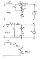
- FIG. 1 is a diagrammatic illustration of a preferred form of starting and operating apparatus of the invention:
- FIG. 2 is a diagrammatic illustration of an alternative form of starting and operating apparatus of the invention; and
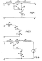
- FIGS. 3-6 are diagrammatic illustrations of the operational phases of the embodiment of FIG. 1.
- For a better understanding of the present invention, together with other and further objects, advantages and capabilities thereof, reference is made to the following disclosure and appended claims in connection with the accompanying drawings.
- Referring to FIG. 1 of the drawings, a preferred apparatus for starting and operating high intensity discharge lamps includes a first pair of
terminals 9 and 11 formed for connection to an AC voltage source such as a 220v AC source. The apparatus also includes a second pair ofterminals intensity discharge lamp 17 such as a metal halide lamp, a high pressure sodium lamp, a mercury vapor lamp, etc. - A ballast means 19, illustrated as an inductor, and a transformer 21 having primary and
secondary windings tap 27 series connect one 9 of the first pair ofterminals 9 and 11 to one 13 of the second pair ofterminals bilateral switch 29, preferably a sidac because of its current carrying capabilities, is connected to thetap 27 of the transformer 21. AnAC impedance 31, illustrated as a capacitor, but may be in the form of an inductor or resistor, and athermal cutout device 33 are in series connection with thebilateral switch 29 and connected to the other one 11 and 15 of the first and second pairs of terminals. Also, a charge storage means 35 or second capacitor is connected to thejunction 37 of the series connected ballast means 19 and transformer 21 and to the junction 39 of thebilateral switch 29 andAC impedance 31. - In an alternative embodiment. FIG. 2, the first pair of
terminals terminals intensity discharge lamp 49. A ballast means 51 in the form of a series connectedinductor 53 andcapacitor 54 is in series connection with aninductor 55 intermediate one. 41 of the first and one 45 of the second pairs of terminals. - A semiconductor
bilateral switch 57 is connected to one end of theinductor 55 and one 45 of the second pair ofterminals capacitor 61 coupled to ajunction 63 of theother one 43 of the first and second pairs ofterminals capacitor 65 is coupled to thejunction 67 of the ballast means 51 andinductor 55 and to thejunction 69 of the series connected inductor 59 andcapacitor 61. Moreover, aresistor 71 is shunted across thecapacitor 61 and coupled to thecapacitor 65. Thus, thesecondary winding 25 of FIG. 1 may be omitted for applications requiring only about 1000 to 2000-volts. Moreover, the thermal cutout device, 33 of FIG. 1, may also be omitted if automatic cutout is not desired. - As to operation. FIG. 3 illustrates the apparatus of FIG. 1 when power is first applied to the
terminals 9 and 11. Initially, thecapacitors bilateral switch 29 andarc discharge lamp 17 are in an off or non-conductive state. Thecapacitors ballast inductor 19 with the charging voltage appearing mainly across thecapacitor 35 because the impedance of thecapacitor 35 is much larger than the impedance of thecapacitor 31. Thus the current 12 through thecapacitor 35 is substantially equal to the current 11 of theballast inductor 19. - The voltage developed across the
capacitor 35 is impressed across thebilateral switch 29 by way of theprimary winding 23 of the transformer 21. (FIG. 4) When the breakdown voltage of thebilateral switch 29 is reached, the resistance of thebilateral switch 29 will suddenly decrease causing thecapacitor 35 to discharge through the saturableprimary winding 23 andbilateral switch 29 in a resonant manner. After a delay, the current sensitive magnetic switch orprimary winding 23 saturates allowing thecapacitor 35 to charge to a maximum value through the winding 23. - Importantly, the core of the current sensitive magnetic switch or
primary winding 23 will drop out of saturation when the resonating current approaches the next zero value (FIG. 4) turning off thebilateral switch 29 allowing for higher circuit oscillation frequencies than are obtainable with only thebilateral switch 29. Thecapacitor 35 is left in a fully reversed charged state which provides an additional "initial charged condition" for voltage boosting during the next oscillation cycle. In other words, the voltage across thecapacitor 35 again begins to change in the original direction but the current and voltage of thecapacitor 35 do not start at zero. Since the reverse charging of thecapacitor 35 by way of the first untuned, uncritical oscillating path of theprimary winding 23 and thebilateral switch 29 occurs quickly relative to the initial charging of thecapacitor 35 via theballast inductor 19, the current through theballast inductor 19 does not change appreciably. In addition, the line voltage can be considered nearly constant since the frequency thereof is so much lower than the oscillation frequency of the first oscillating path for boosting the voltage of thecapacitor 35. - As the magnitude of the voltage across the capacitor decreases, the decreasing current in the
primary winding 23 and thebilateral switch 29 drops below the holding current of thebilateral switch 29 and thebilateral switch 29 turns off. FIG. 5 Thecapacitor 35 again charges in the same direction and the current of theballast inductor 19 increases slightly causing an increase in the final voltage across thecapacitor 35. The cycle repeats with thecapacitor 35 voltage andballast inductor 19 current continuing to increase in value. Also, the voltage across the primary winding 23 is stepped up by the winding 25 to provide a high starting voltage for thedischarge lamp 17. This high starting voltage is the sum of the voltages developed across thewindings - When the
lamp 17 lights, a new or second resonant loop is formed, as illustrated in FIG. 6, and oscillation of the starter ceases due to the limiting of the voltage available to thebilateral switch 29. Since the saturated inductance of the primary winding 23 and winding 25 is orders of magnitude smaller than that of theballast inductor 19, the new loop will now control the charging of thecapacitor 35. Moreover, the breakdown voltage of thebilateral switch 29 is chosen to be greater than the peak voltage of thedischarge lamp 17, therefore, no starting action will occur. - It should be noted that the primary winding 23 performs a special function in that it acts as a magnetic switch. This magnetic switch action of the primary winding 23 insures that the discharge of the
capacitor 35 does not take place before recharging thereof by way of theballast inductor 19 is finished. The primary winding ormagnetic switch 23 also helps to insure that thebilateral switch 29 turns off. When the voltage of thecapacitor 35 reaches the breakover voltage of thebilateral switch 29, thebilateral switch 29 will turn on and thecapacitor 35 will begin to discharge through the primary winding 23 which has a very high inductance until it saturates causing very little discharging of thecapacitor 35 immediately after thebilateral switch 29 turns on. - Importantly, the low current unsaturated inductance of the primary winding 23 is similar to the inductance of the
ballast inductor 19 while the high current saturated inductance of the primary winding 23 is much less than the inductance of theballast inductor 19. Also, thecapacitor 35 continues to change after thebilateral switch 29 turns on or becomes conductive by way of theballast inductor 19 allowing the voltage across thecapacitor 35 to build up. When the primary winding 23 saturates, it must have the capability to switch quickly and complete reverse charging of thecapacitor 35. Accordingly. the best ferrite magnetic core materials for the transformer 21 which includes the primary andsecondary windings - While all of the above is happening, the line voltage and the voltage of the
capacitor 31 continue to change so that oscillation is not quite continuous. However, so long as the line voltage and the voltage of thecapacitor 31 are sufficiently different, oscillation will occur. Also, phase shifting of the modulated RF waveform will occur due to the relationship between line voltage, current and the voltage of thecapacitor 31. Since the voltage on thecapacitor 31 depends upon oscillator action, the circuit produces a somewhat random appearing modulated RF envelope. Moreover, thecapacitor 31 further acts to limit starter current and hence output voltage since it is an AC impedance in series with the starter apparatus. - During this period, the
thermal cutout device 33 self heats due to the series starter current passing therethrough and after a period of time, heats to a temperature sufficient to cause a sudden rise in resistance by several orders of magnitude. Thereupon, the starter current will greatly decrease and the generation of high voltage pulses will decrease. Thus, thethermal cutout device 33 will effectively shut off the starter should the lamp fail to light. Thecutout device 33 stops self-heating when power is removed or the lamp lights and the starter is ready to instantly come alive if power is restored or the lamp goes out. - Thus. the starter system does not continue to apply high voltage pulse potentials to the
discharge lamp 17 should it fail to ignite whereby deterioration of the discharge lamp circuit would result. However. thecutout device 33 does permit the starter system to immediately activate should a power outage occur. Moreover, an increase in lamp reignition voltage or an increase in reignition voltage due to lamp ageing will cause the automatic activation of the starter system to provide lamp power during powerline dips or voltage reignition humps occurring each half cycle of lamp voltage. - Accordingly, a compact, low cost electronic starter for converting low voltage, high current low frequency energy into high voltage, low current high frequency energy stored in an oscillator circuit operable at a frequency in the range of about 20 to 50 KHZ has been provided. The high voltage and current are provided simultaneously to effect rapid starting and re-starting of arc discharge lamps since a relatively wide high energy pulse, rather than narrow starting pulse potentials, is provided. Also, the starter acts in a series injection mode permitting the use of either lead or lag-type ballasts since the starter does not inject power back into the power line. Moreover, the capability to extend lamp life, to reignite the lamp upon failure of the source voltage and to protect the discharge lamp from bombardment by high voltage pulse potentials should the lamp fail to light are features unavailable in other known structures.
- Additionally, typical, but in no way limiting, are the following component values for the embodiment of FIG. 1:


- While there has been shown and described what is at present considered the preferred embodiments of the inventions, it will be obvious to those skilled in the art that various changes and modifications may be made therein without departing from the invention as defined by the appended claims.
Claims (22)
Applications Claiming Priority (2)
| Application Number | Priority Date | Filing Date | Title |
|---|---|---|---|
| US06/702,107 US4678968A (en) | 1985-02-15 | 1985-02-15 | High intensity discharge lamp starting and operating apparatus |
| US702107 | 1985-02-15 |
Publications (2)
| Publication Number | Publication Date |
|---|---|
| EP0195248A2 true EP0195248A2 (en) | 1986-09-24 |
| EP0195248A3 EP0195248A3 (en) | 1987-02-25 |
Family
ID=24819892
Family Applications (1)
| Application Number | Title | Priority Date | Filing Date |
|---|---|---|---|
| EP86101913A Withdrawn EP0195248A3 (en) | 1985-02-15 | 1986-02-14 | High intensity discharge lamp starting and operating apparatus |
Country Status (4)
| Country | Link |
|---|---|
| US (1) | US4678968A (en) |
| EP (1) | EP0195248A3 (en) |
| JP (1) | JPS61193399A (en) |
| AU (1) | AU578800B2 (en) |
Cited By (4)
| Publication number | Priority date | Publication date | Assignee | Title |
|---|---|---|---|---|
| EP0337554A1 (en) * | 1988-04-13 | 1989-10-18 | Koninklijke Philips Electronics N.V. | Switching arrangement |
| FR2659915A1 (en) * | 1990-03-23 | 1991-09-27 | Carello Spa | PROJECTOR FOR VEHICLES, ESPECIALLY FOR MOTOR VEHICLES. |
| GB2305032A (en) * | 1995-08-29 | 1997-03-26 | Hubbell Inc | Inhibiting operation of a starting circuit for a high pressure discharge lamp |
| GB2319677A (en) * | 1996-11-19 | 1998-05-27 | Micro Tech Ltd | Discharge lamp starting and operating circuit |
Families Citing this family (15)
| Publication number | Priority date | Publication date | Assignee | Title |
|---|---|---|---|---|
| US4745341A (en) * | 1986-03-25 | 1988-05-17 | Cooper Industries | Rapid restrike starter for high intensity discharge lamps |
| US5051664A (en) * | 1987-12-16 | 1991-09-24 | Droho Joseph S | Ignitor circuit for discharge lamps with novel ballast |
| US4939430A (en) * | 1987-12-16 | 1990-07-03 | Advance Transformer Company | Ignitor circuit for discharge lamps with novel ballast |
| US5017840A (en) * | 1987-12-16 | 1991-05-21 | North American Philips Corporation | Ignitor circuit for discharge lamps with novel ballast |
| US4876486A (en) * | 1987-12-30 | 1989-10-24 | Advance Transformer Co. | Two-lead starter circuit for a gaseous discharge lamp |
| US5059867A (en) * | 1990-04-03 | 1991-10-22 | General Electric Company | Ballast circuit with improved transfer functions |
| US5608296A (en) * | 1992-03-24 | 1997-03-04 | Philips Electronics North America Corp. | Multiple pulsing throughout the glow mode |
| WO1996025022A1 (en) * | 1995-02-07 | 1996-08-15 | Philips Electronics N.V. | Circuit arrangement for ignition of a high intensity discharge lamp |
| US6100652A (en) * | 1998-11-12 | 2000-08-08 | Osram Sylvania Inc. | Ballast with starting circuit for high-intensity discharge lamps |
| DE19923237A1 (en) * | 1999-05-20 | 2000-11-23 | Patent Treuhand Ges Fuer Elektrische Gluehlampen Mbh | Circuit arrangement, associated electrical system and discharge lamp with such a circuit arrangement and method for its operation |
| US6194845B1 (en) * | 1999-11-03 | 2001-02-27 | Osram Sylvania Inc. | Ballasts with tapped inductor arrangements for igniting and powering high intensity discharge lamps |
| WO2001069985A1 (en) * | 2000-03-16 | 2001-09-20 | Koninklijke Philips Electronics N.V. | Switching ballast device |
| US6958579B2 (en) * | 2002-08-07 | 2005-10-25 | Ruud Lighting, Inc. | Thermally-protected ballast for high-intensity-discharge lamps |
| DE102004031944A1 (en) * | 2004-06-30 | 2006-01-19 | Deutsche Thomson-Brandt Gmbh | Power supply for a metal halide lamp |
| DE102007026317A1 (en) * | 2007-06-06 | 2008-12-11 | Osram Gesellschaft mit beschränkter Haftung | High-pressure discharge lamp with improved ignition device and ignition device for a gas discharge lamp |
Citations (3)
| Publication number | Priority date | Publication date | Assignee | Title |
|---|---|---|---|---|
| US4162429A (en) * | 1977-03-11 | 1979-07-24 | Westinghouse Electric Corp. | Ballast circuit for accurately regulating HID lamp wattage |
| FR2454246A1 (en) * | 1979-04-12 | 1980-11-07 | Gen Electric | Ignition circuit for high pressure arc discharge lamp - has voltage doubler and oscillating inverter with transformer fed by pulse with capacitor and diode in secondary circuit |
| US4376911A (en) * | 1979-12-28 | 1983-03-15 | New Nippon Electric Co., Ltd. | Circuit system for lighting a discharge lamp or lamps |
Family Cites Families (10)
| Publication number | Priority date | Publication date | Assignee | Title |
|---|---|---|---|---|
| US2392192A (en) * | 1946-01-01 | Ignition system | ||
| US2901670A (en) * | 1959-08-25 | Ignition system | ||
| US1955519A (en) * | 1934-04-17 | Ignition system | ||
| US3334270A (en) * | 1964-09-04 | 1967-08-01 | Gen Electric | Discharge lamp circuit |
| US3753037A (en) * | 1970-02-26 | 1973-08-14 | New Nippon Electric Co | Discharge-lamp operating device using thyristor oscillating circuit |
| JPS5215178A (en) * | 1975-07-28 | 1977-02-04 | Nec Home Electronics Ltd | High tension (or voltage) generating circuit |
| US4209730A (en) * | 1978-07-14 | 1980-06-24 | Larry McGee Company | Starting circuit for gaseous discharge lamps |
| US4275337A (en) * | 1979-08-08 | 1981-06-23 | General Electric Company | Starting and operating circuit for gaseous discharge lamps |
| JPS5638795A (en) * | 1979-09-07 | 1981-04-14 | Iwasaki Electric Co Ltd | Starter for discharge lamp |
| JPS58154198A (en) * | 1982-03-09 | 1983-09-13 | オイ・ヘルバ− | Device for firing lamp |
-
1985
- 1985-02-15 US US06/702,107 patent/US4678968A/en not_active Expired - Lifetime
-
1986
- 1986-02-14 JP JP61029131A patent/JPS61193399A/en active Pending
- 1986-02-14 EP EP86101913A patent/EP0195248A3/en not_active Withdrawn
- 1986-02-14 AU AU53609/86A patent/AU578800B2/en not_active Ceased
Patent Citations (3)
| Publication number | Priority date | Publication date | Assignee | Title |
|---|---|---|---|---|
| US4162429A (en) * | 1977-03-11 | 1979-07-24 | Westinghouse Electric Corp. | Ballast circuit for accurately regulating HID lamp wattage |
| FR2454246A1 (en) * | 1979-04-12 | 1980-11-07 | Gen Electric | Ignition circuit for high pressure arc discharge lamp - has voltage doubler and oscillating inverter with transformer fed by pulse with capacitor and diode in secondary circuit |
| US4376911A (en) * | 1979-12-28 | 1983-03-15 | New Nippon Electric Co., Ltd. | Circuit system for lighting a discharge lamp or lamps |
Cited By (7)
| Publication number | Priority date | Publication date | Assignee | Title |
|---|---|---|---|---|
| EP0337554A1 (en) * | 1988-04-13 | 1989-10-18 | Koninklijke Philips Electronics N.V. | Switching arrangement |
| US4958107A (en) * | 1988-04-13 | 1990-09-18 | North America Philips Corporation | Switching arrangement for HID lamps |
| FR2659915A1 (en) * | 1990-03-23 | 1991-09-27 | Carello Spa | PROJECTOR FOR VEHICLES, ESPECIALLY FOR MOTOR VEHICLES. |
| GB2305032A (en) * | 1995-08-29 | 1997-03-26 | Hubbell Inc | Inhibiting operation of a starting circuit for a high pressure discharge lamp |
| GB2305032B (en) * | 1995-08-29 | 2000-03-22 | Hubbell Inc | Lamp starting circuit |
| GB2319677A (en) * | 1996-11-19 | 1998-05-27 | Micro Tech Ltd | Discharge lamp starting and operating circuit |
| GB2319677B (en) * | 1996-11-19 | 2001-04-18 | Micro Tech Ltd | Lamp driver circuit and method |
Also Published As
| Publication number | Publication date |
|---|---|
| JPS61193399A (en) | 1986-08-27 |
| AU578800B2 (en) | 1988-11-03 |
| AU5360986A (en) | 1986-08-21 |
| US4678968A (en) | 1987-07-07 |
| EP0195248A3 (en) | 1987-02-25 |
Similar Documents
| Publication | Publication Date | Title |
|---|---|---|
| US4678968A (en) | High intensity discharge lamp starting and operating apparatus | |
| US4461982A (en) | High-pressure metal vapor discharge lamp igniter circuit system | |
| EP0049465B1 (en) | Apparatus and method for starting high intensity discharge lamps | |
| US4079292A (en) | Arc discharge sustaining circuit system for a discharge lamp | |
| US4890041A (en) | High wattage HID lamp circuit | |
| US6091208A (en) | Lamp ignitor for starting conventional hid lamps and for starting and restarting hid lamps with hot restrike capability | |
| JPH067517B2 (en) | High-pressure discharge lamp ignition device | |
| US4959593A (en) | Two-lead igniter for HID lamps | |
| US4398130A (en) | Arc lamp lighting unit with low and high light levels | |
| US5059870A (en) | Electronic solid state starter for fluorescent lamps | |
| US5013977A (en) | Ignitor for high pressure arc discharge lamps | |
| JPS6160555B2 (en) | ||
| US4103209A (en) | Add-on instant restrike device for an hid lamp | |
| US6373199B1 (en) | Reducing stress on ignitor circuitry for gaseous discharge lamps | |
| US5572093A (en) | Regulation of hot restrike pulse intensity and repetition | |
| US3609452A (en) | Lamp driver circuit | |
| US2916669A (en) | Starting circuit for gaseous discharge lamps | |
| US5896013A (en) | Operating circuit for an inductively ballasted arc discharge lamp | |
| US4048543A (en) | Discharge lamp operating circuit | |
| GB2066596A (en) | An arc lamp lighting unit with low and high light levels | |
| JPH0744076B2 (en) | Discharge lamp lighting device | |
| JP2562816B2 (en) | Discharge lamp lighting device | |
| JPS6120117B2 (en) | ||
| JPS61110997A (en) | Discharge lamp lighting apparatus | |
| KR830000939B1 (en) | Lighting system of discharge lamp |
Legal Events
| Date | Code | Title | Description |
|---|---|---|---|
| PUAI | Public reference made under article 153(3) epc to a published international application that has entered the european phase |
Free format text: ORIGINAL CODE: 0009012 |
|
| 17P | Request for examination filed |
Effective date: 19860214 |
|
| AK | Designated contracting states |
Kind code of ref document: A2 Designated state(s): BE DE FR GB NL |
|
| PUAL | Search report despatched |
Free format text: ORIGINAL CODE: 0009013 |
|
| AK | Designated contracting states |
Kind code of ref document: A3 Designated state(s): BE DE FR GB NL |
|
| RHK1 | Main classification (correction) |
Ipc: H05B 41/04 |
|
| 17Q | First examination report despatched |
Effective date: 19890912 |
|
| STAA | Information on the status of an ep patent application or granted ep patent |
Free format text: STATUS: THE APPLICATION IS DEEMED TO BE WITHDRAWN |
|
| 18D | Application deemed to be withdrawn |
Effective date: 19910829 |
|
| RIN1 | Information on inventor provided before grant (corrected) |
Inventor name: LESTER, JAMES N. |