EP0195191B1 - Passive mark system for driving and controlling driverless carriage and assembly units - Google Patents
Passive mark system for driving and controlling driverless carriage and assembly units Download PDFInfo
- Publication number
- EP0195191B1 EP0195191B1 EP86100908A EP86100908A EP0195191B1 EP 0195191 B1 EP0195191 B1 EP 0195191B1 EP 86100908 A EP86100908 A EP 86100908A EP 86100908 A EP86100908 A EP 86100908A EP 0195191 B1 EP0195191 B1 EP 0195191B1
- Authority
- EP
- European Patent Office
- Prior art keywords
- track
- passive
- passive track
- vehicle
- bar code
- Prior art date
- Legal status (The legal status is an assumption and is not a legal conclusion. Google has not performed a legal analysis and makes no representation as to the accuracy of the status listed.)
- Expired
Links
- 238000005314 correlation function Methods 0.000 claims abstract description 13
- 230000003287 optical effect Effects 0.000 claims description 6
- 238000013461 design Methods 0.000 claims description 5
- 238000010422 painting Methods 0.000 claims description 3
- 230000010355 oscillation Effects 0.000 claims description 2
- 230000001276 controlling effect Effects 0.000 claims 2
- 230000000875 corresponding effect Effects 0.000 claims 2
- 230000002596 correlated effect Effects 0.000 claims 1
- 239000002184 metal Substances 0.000 claims 1
- 238000007592 spray painting technique Methods 0.000 claims 1
- 238000011156 evaluation Methods 0.000 abstract description 10
- 238000000034 method Methods 0.000 abstract description 9
- 230000008569 process Effects 0.000 abstract description 3
- 238000012544 monitoring process Methods 0.000 abstract description 2
- 238000005259 measurement Methods 0.000 description 10
- 230000001939 inductive effect Effects 0.000 description 5
- 238000004364 calculation method Methods 0.000 description 3
- 230000008859 change Effects 0.000 description 3
- 238000003384 imaging method Methods 0.000 description 3
- 239000000463 material Substances 0.000 description 3
- 238000012545 processing Methods 0.000 description 3
- 210000002023 somite Anatomy 0.000 description 3
- 238000012546 transfer Methods 0.000 description 3
- 238000004026 adhesive bonding Methods 0.000 description 2
- 238000012937 correction Methods 0.000 description 2
- 230000001419 dependent effect Effects 0.000 description 2
- 238000005516 engineering process Methods 0.000 description 2
- 230000001965 increasing effect Effects 0.000 description 2
- 238000012423 maintenance Methods 0.000 description 2
- 238000004519 manufacturing process Methods 0.000 description 2
- 238000012986 modification Methods 0.000 description 2
- 230000004048 modification Effects 0.000 description 2
- 230000008439 repair process Effects 0.000 description 2
- 238000009420 retrofitting Methods 0.000 description 2
- 238000005507 spraying Methods 0.000 description 2
- 229910000859 α-Fe Inorganic materials 0.000 description 2
- 241001136792 Alle Species 0.000 description 1
- 238000012935 Averaging Methods 0.000 description 1
- XAGFODPZIPBFFR-UHFFFAOYSA-N aluminium Chemical compound [Al] XAGFODPZIPBFFR-UHFFFAOYSA-N 0.000 description 1
- 229910052782 aluminium Inorganic materials 0.000 description 1
- 230000004888 barrier function Effects 0.000 description 1
- 230000005540 biological transmission Effects 0.000 description 1
- 230000015572 biosynthetic process Effects 0.000 description 1
- 238000004140 cleaning Methods 0.000 description 1
- 238000000205 computational method Methods 0.000 description 1
- 238000010276 construction Methods 0.000 description 1
- 238000011109 contamination Methods 0.000 description 1
- 230000007547 defect Effects 0.000 description 1
- 238000009795 derivation Methods 0.000 description 1
- 238000001514 detection method Methods 0.000 description 1
- 238000011161 development Methods 0.000 description 1
- 230000018109 developmental process Effects 0.000 description 1
- 230000000694 effects Effects 0.000 description 1
- 238000010292 electrical insulation Methods 0.000 description 1
- 230000036039 immunity Effects 0.000 description 1
- 230000006698 induction Effects 0.000 description 1
- 230000010354 integration Effects 0.000 description 1
- 230000005693 optoelectronics Effects 0.000 description 1
- 230000005855 radiation Effects 0.000 description 1
- 230000009467 reduction Effects 0.000 description 1
- 238000007430 reference method Methods 0.000 description 1
- 238000002310 reflectometry Methods 0.000 description 1
- 239000004065 semiconductor Substances 0.000 description 1
- 230000035945 sensitivity Effects 0.000 description 1
- 238000012360 testing method Methods 0.000 description 1
Images


Classifications
-
- G—PHYSICS
- G05—CONTROLLING; REGULATING
- G05D—SYSTEMS FOR CONTROLLING OR REGULATING NON-ELECTRIC VARIABLES
- G05D1/00—Control of position, course, altitude or attitude of land, water, air or space vehicles, e.g. using automatic pilots
- G05D1/02—Control of position or course in two dimensions
- G05D1/021—Control of position or course in two dimensions specially adapted to land vehicles
- G05D1/0231—Control of position or course in two dimensions specially adapted to land vehicles using optical position detecting means
- G05D1/0244—Control of position or course in two dimensions specially adapted to land vehicles using optical position detecting means using reflecting strips
-
- G—PHYSICS
- G05—CONTROLLING; REGULATING
- G05D—SYSTEMS FOR CONTROLLING OR REGULATING NON-ELECTRIC VARIABLES
- G05D1/00—Control of position, course, altitude or attitude of land, water, air or space vehicles, e.g. using automatic pilots
- G05D1/02—Control of position or course in two dimensions
- G05D1/021—Control of position or course in two dimensions specially adapted to land vehicles
- G05D1/0231—Control of position or course in two dimensions specially adapted to land vehicles using optical position detecting means
- G05D1/0234—Control of position or course in two dimensions specially adapted to land vehicles using optical position detecting means using optical markers or beacons
Definitions
- the present invention relates to a pass i vspur arrangement for guiding and controlling driverless transport and assembly units, in particular industrial trucks, containing a passive track attached to the ground as a guideline with at least one feature different from the rest of the roadway, and a vehicle-supported scanning device for tracking the passive track.
- Such passive track systems are generally applicable when it comes to guiding mobile objects along a guideline and making optimal use of the flexibility of trackless conveyors, such as. B. in the construction and operation of flexible manufacturing systems.
- the present invention is directed to a vehicle guidance system with a passive guideline, as is known, for example, from DE-A-2 459 358, FR-A - 2 406 245 or DE-A-2 949 204.
- the two passive track guidance systems mentioned above work on the principle of brightness balance and use a light band as a guideline.
- Light emitted by the vehicle is reflected on the bright band and received by two vehicle-based light sensors, each of which generates a signal that is proportional to the average brightness within the corresponding measurement window. If the first light sensor above the associated measurement window now delivers a larger signal than the second light sensor above its measurement window, the vehicle's substantial tracking with respect to the light band is corrected so that both measurement windows have the same average sanctity and the brightness balance is thus restored.
- the sensitivity of the system is a function of the contrast.
- the tracking system only behaves monotonously as long as the outer edges lie within the dark bands and the inner edges within the light band in both measurement windows. Outside of this range, indifferent behavior or even behavior with inverse signs can be observed. This results in a reduced capture area when tracking, which can impair their reliability.
- DE-A-2 459 358 provides a plurality of sensors arranged transversely to the passive guideline.
- the position of the guideline is determined by comparing the brightness values recorded by the sensors.
- a reference value is formed from the mean value of the light received by all sensors.
- a reflectivity in the guideline is still necessary that is at least a few times as large as that of the neighboring areas.
- the invention solves the problem of increasing the flexibility and simplifying the structure and function of an operating system for track-guided transport and assembly units.
- the innovation aims to design a guideline in such a way that it can be easily and quickly attached to the floor and also removed again and at the same time serves to guide and function control the vehicles.
- the new operating system is also said to be largely tolerant of soiling of the guideline and roadway, and to have increased immunity to interference and functional reliability.
- the first advantages result from the use of an optical system, the commercially available sensors of which have a higher resolution than others at the given minimum distances, e.g. B. inductive sensors.
- This enables the vehicle to determine its current position over the road very precisely and thus to follow the passive lane with great accuracy.
- the higher resolution of the reading device means a greater information density; and without loss of legibility.
- a large number of the mostly localized control functions can be saved on a short section of the route, which considerably simplifies the disposition of the functions to be performed by the vehicle at intersections and transfer points.
- the passive track system according to the invention has self-monitoring and that precautionary maintenance is possible on the basis of a quality factor that is continuously calculated.
- lane guidance systems that are sensitive to soiling can also be operated outdoors or under generally difficult conditions the. Any faults in the roadway or scanning device are indicated in good time by the quality factor so that they can be remedied before there is an interruption in operation.
- the system parts for tracking and function control are both optoelectronic, that is to say they are designed using uniform technology. This makes it possible to combine the read heads for passive track and bar code in an integrated optics block.
- various elements such as electronic prints, housings, connecting cables, etc. can be used for both different functions, namely both for tracking and for code reading. This simplifies assembly, assembly and adjustment of the passive track system and simplifies its maintenance, including the disposition of spare parts, which generally leads to an inexpensive solution.
- the innovation is fully compatible with conventional inductive tracking systems.
- Its reading device consisting of a reading head and evaluation electronics, corresponds functionally and largely in the interface to the vehicle control to the known ferrite antenna with subsequent signal processing in induction loops.
- the new passive track system is therefore particularly suitable for retrofitting and retrofitting existing inductive tracking systems.
- Fig. 1 shows a possible embodiment of the passive track system, as is provided for guiding and controlling a vehicle FZ.
- the vehicle FZ consists of two separate driving cells connected with a load-bearing support body 3 and each with a joint 4, 4 ', which are constructed in a mirror-symmetrical manner and which are constructed identically and of which only one is shown in the present example and designated by 2.
- Each driving cell 2 essentially contains a steerable drive wheel R A, not shown, with driving and steering servo, two trailing support wheels Rs, Rs' and the necessary reading devices 13, 20 for scanning the passive track 9 or the bar code 28.
- the vehicle FZ designed in this way is completely symmetrical in terms of forward / reverse travel.
- the passive track 9 which can be permanently attached to the floor using simple methods such as painting, spraying or gluing and can also be easily removed for repair or modification, normally consists of a highly reflective plastic tape glued to the floor.
- the chosen plastic has a sufficiently high contrast to a large number of floors of different qualities, has a high wear resistance and is resistant to common materials used in industry.
- a passive track 9 designed in this way can also be cleaned with cleaning machines.
- the passive track guidance system consists of the passive track 9 attached to the floor and the vehicle-supported passive track reading devices 13, 13 'for forward and backward travel with their reading heads 14, 14' and evaluation electronics 16, 16 '.
- the read heads 14, 14 'each contain 8 track sensors SS 1 , SS 2 ...
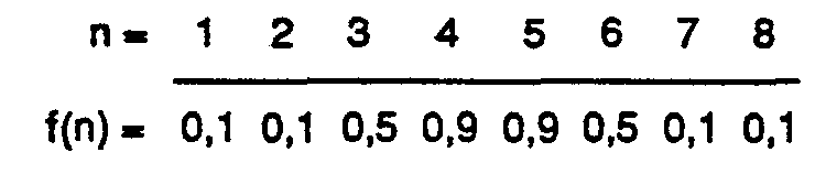
- Sl 1 , SL 2 ... SL 16 denote 16 lane positions, in the areas of which the roadway has a brightness value, which depends on whether the associated brightness measurement window is entirely in Pass i vspur 9 (SLs; SL 9 ) or entirely in the floor areas 11, 12 (SLi to SLs; SL 1 to SL 16 ) adjoining on both sides or half each in the passive track 9 and in the floor areas 11, 12 (SL 7 ; SLio) adjoining on both sides.
- These brightness values represent a discrete brightness profile of the road running in the transverse direction, which serves as a "pattern".
- a possible lane deviation is determined by the vehicle by defining its current lane position, which is defined by light values measured by the track sensors SS 1 , SS 2 ... SS 8 or SS 1 ', SS 2 ... SS 8 ' compares to the "pattern".
- the passive track control system also includes the bar code 28, which is designed as part of the passive track 9, and the vehicle-based bar code reading device 20, comprising a read head 21 with code sensors CS 1 , CS 2 ... CSs and evaluation electronics 24.
- FIG. 2a shows the passive lane guidance system in connection with two vehicles FZ and FZ ', which are centered with respect to the passive lane 9 or are shifted to the right by 1.25 lane positions on the carriageway.
- the passive track reading device 13 composed of the read head 14 and evaluation electronics 16 corresponds functionally and largely in the interface to the vehicle control to the known ferrite antenna for inductive loops with subsequent signal processing, so that optionally one or the other tracking system can be used.
- the position information transmitted to the computer of the vehicle control via parallel output 30 for de systems in the form of a digital value in the value range - 127 to + 128.
- the reading device is largely insensitive to external light such as workplace lighting by means of incandescent or gas discharge lamps, sunlight and IR radiation from various light barriers, etc., which is also achieved by a certain shielding effect of the vehicle body, especially against the top.
- the number of track sensors was set to n - 8.
- the individual sensors are mounted linearly at a distance of 12.5 mm across the direction of travel.
- the active sensor area is 3.2 x 1.55 mm.
- Up to two reading heads can be connected to the evaluation electronics 16 via the cable 25.
- This contains a computer and an Interfaoe print 17 or 18 and is equipped to perform all the necessary functions.
- the software of the computer print contains all the necessary programs for the calculation of the track deposit by means of the procedure for the control of tests, which will be explained later in detail, such as B. track start, end of lane and for data transmission to the vehicle computer.
- the reading head 14 can be provided with a 90-degree beam deflection.
- LEDs or IR emitters 45 illuminate the roadway area located in the area of the reading head 14, the light reflected within the track brightness measurement window SF 1 , SF 2 ... SF B illuminating after deflection in a prism 38 integrated with an 8-fold collecting line 37 the active area of the track sensors SS 1 , SS2 ... SSS is guided.
- simple optics with a 4: 1 imaging scale are installed.
- An active track brightness measurement window SF 1 , SF 2 ... SFs of 12.8 x 6.20 mm per track sensor is achieved.
- FIG. 3a shows the cross-correlation function curves 39, 40 as they correspond to the centered or decentered lane position of the two vehicles FZ and FZ 'in FIG. 2a.
- the grid dimension d used results in discrete functions consisting of the base values 41 which are assigned to the base points 1 to 9.
- the maxima 42 and 43 are important because their assigned support points, regardless of the brightness of the passive lane 9 or the background, coincide with the lane positions of the vehicles FZ and FZ and thus indicate their lane deviation.
- the function maxima 42, 43 can fall on a base value or - which should occur far more frequently - take a position between the base values. In the latter case, the method shown in Fig. 3b is used.
- the discrete cross-correlation function is replaced by a continuously running curve 48, which is obtained by quadratic interpolation from the support values 49, 50 and 51 in the support points M -1, M and M + 1.
- the absolute maximum value is then designated 52 and assumes the position M m ax.
- the corresponding quality factor of the passive lane system is entered in a table for each possible assignment between 8 route sections and 5 vehicles, "1" for unusable, "255" for ideal condition. These quality factors are calculated by the vehicles, but always include the overall quality of the part of the passive lane system based on a vehicle FZ and the passive lane 9 in the assigned route section 36. If several vehicles are used on the same layout, the quality factors of the route sections are determined by each individual vehicle transmitted to the higher-level stationary control device.
- the stationary computer which is also required when using processor-controlled vehicles for disposition, etc., maintains the table according to FIG. 4. It can be seen from this that there is no total defect. On the other hand, it emerges from a majority consideration that the pass i vspur 9 in the route section No. 2 is dirty or worn at one or more points and that the vehicle No. 4 and possibly also the vehicle No. 5 should be checked.
- the passive track system as a passive track control system, consisting of the bar code 28 attached to the floor and the bar code reading device 20 installed in the vehicle FZ.
- the bar code 28 basically consists of transverse breaks 27 in the guideline and is therefore an integral part of the passive track 9.
- the bar code 28 can be permanently affixed to the floor by processes such as painting, spraying or gluing and can also be removed for repair or modification.
- the bar code 28 consists of a glued-on, low-reflection plastic band 29 which serves as a contrast-enhancing background and on which the highly reflective code strips 31 are applied. These consist of the same material as the passive track 9, but exceed the same in width in order to enable reliable code reading even with larger track deviations.
- the code strips 31 differ by two different lengths as logic “0” and logic “1", so that in the present exemplary embodiment they have the following dimensions: 53 x 5 mm for logic "0", 53 x 11.5 mm for logic "1".
- the distance between the individual code strips 31 is uniformly 8 mm.
- Striking interruptions 44, 44 ', both ⁇ 43.5 mm at the beginning and at the end of the code sequence, are provided for initializing or ending the code reading.
- Another variant for bar code 28 is to attach a thin aluminum sheet to the floor, which is anodized black / white in the pattern of the code.
- the bar code reading device 20 installed in the vehicle FZ for reading the bar code 28 consists of a reading head 21 and evaluation electronics 24 and is integrated in the passive track reading device 13, 13 'or is constructed separately when the passive track control system is used alone.
- the code sensors CS 1 , CS 2 ... CSs with an active sensor area of 1 x 1 mm are arranged one behind the other in the direction of travel at a distance of 1.5 mm.
- An optical code area of 2 x 2 mm is achieved by optics with a 2: 1 imaging scale.
- a semiconductor light source 15, 15 ' is installed on each side of the code sensors CS 1 , CS 2 ... CS S.
- a maximum of two reading heads 21 can be connected to the evaluation electronics 24 via a connecting cable 54 each. This contains a computer print 55 and an interface print 56 and is equipped to perform all functions that are part of the normal operating sequence.
- FIG. 6 The integration of the read heads 14 and 21 for the passive track 9 and the bar code 28 made possible by using a uniform technology is shown in FIG. 6.
- the track sensors SS 1 ... SS 8 and the code sensors CS 1 ... CS 5 with their imaging optics 63 and 64 and lighting diodes 45 and 15 are combined on a print 61 in the housing 62 to form an optics block 65 which is controlled by electronics 66 and the connector 67 is connected to the vehicle computer 17.
- This embodiment variant of the invention dispenses with the right-angled beam deflection in the case of the track sensors SS 1 ... SS 8 and also uses only a light source to illuminate the associated track brightness measurement window SF 1 SF 8 .
- the vehicle FZ determines which area of the TARGET brightness profile best matches the measured ACTUAL brightness profile. The center position of this area then corresponds to the track position of the vehicle FZ.
- the result m is the interpolated location of the maximum of the cross-correlation function in relation to the location M of the maximum base value, which completes the third step.
- information is required at certain points in the route network so that the vehicle (FZ) performs a certain function in the right place, such as, for example, B. Stopping, branching, load transfer, reducing speed, etc.
- additional information is required, such as. B. place or route names, transfer location numbers, etc., in order to ensure as autonomous as possible, independent of fixed facilities operation.
- This information which usually consists of several bits - a data word - and for which the greatest possible spatial accuracy is required, is encoded in the bar code (28). This is read by the code sensors CS 1 ... CS 5 while driving or at a standstill and the information obtained in this way is fed to the vehicle control system.
- the number of thin (logical "0") and thick (logical "1") code strips 31 contained in bar code 28 is limited.
- the number of useful bits is determined depending on the application and remains constant within a system.
- Barcode reading is carried out by the 3 consecutively arranged code sensors CS 1 , CS 2 and CS 4 and is also possible with the vehicle at a standstill or with pendulum movements above the code.
- 3 code reading sensors an oscillation on the code strip 31 with amplitudes up to 5 mm is recognized and multiple evaluations of the same code strip 31 are excluded.
- the code reading is initialized with the code sensors CS 3 and CSs. Because no strobe signal is required, the read head 21 with the code sensors CS 1 ... CS 5 can be guided obliquely over the bar code 28 to +/- 30 °.
- a code strip 31 for logic “0” is recognized in that the code sensors CS 1 , CS 2 and CS 4 change to the “sensor one” state in a combination that is dependent on the reading direction, depending on the previous state.
- a code strip 31 for logic “1” is recognized in that the code sensors CS 1 , CS 2 and CS 4 change to the "sensor one" state regardless of the previous state.
- the beginning or end of the code is generated by a distinctive interruption 44, 44 'of the reflective material, as a result of which all sensors, that is to say code reading and initialization sensors, change to the "sensor zero" state during a longer period.
- the distance between the code strips 31 is selected such that none of the above states for logic "0", logic "1" and the beginning or end of the code can occur. At least one of the 3 code reading sensors CS 1 CS 2 , CS 4 is always in the "sensor one” state.
- the passive track 9 is used twice, namely by the track sensors SS 1 ... SS 8 as a guideline and by the code sensors CS 1 ... CS 5 as a source of information. Bar code 28, together with its actual function for function control, is also used for tracking at the same time. Although the reflective code strips 31 have a lower average brightness value than the regular passive track 9, their contrast is sufficient for tracking.
Landscapes
- Engineering & Computer Science (AREA)
- Physics & Mathematics (AREA)
- General Physics & Mathematics (AREA)
- Aviation & Aerospace Engineering (AREA)
- Radar, Positioning & Navigation (AREA)
- Remote Sensing (AREA)
- Electromagnetism (AREA)
- Automation & Control Theory (AREA)
- Control Of Position, Course, Altitude, Or Attitude Of Moving Bodies (AREA)
- Measuring Volume Flow (AREA)
- Ultra Sonic Daignosis Equipment (AREA)
- Refuse Collection And Transfer (AREA)
- Vending Machines For Individual Products (AREA)
Abstract
Description
Die vorliegende Erfindung betrifft ein Passivspur-Anordnung zur Führung und Steuerung von fahrerlosen Transport- und Montageeinheiten, insbesondere Flurförderzeugen, enthaltend eine als Leitlinie am Boden angebrachte Passivspur mit mindestens einem von der übrigen Fahrbahn unterschiedlichen Merkmal sowie eine fahrzeuggestützte Abtastvorrichtung zur Verfolgung der Passivspur.The present invention relates to a pass i vspur arrangement for guiding and controlling driverless transport and assembly units, in particular industrial trucks, containing a passive track attached to the ground as a guideline with at least one feature different from the rest of the roadway, and a vehicle-supported scanning device for tracking the passive track.
Solche Passivspur-Systeme sind allgemein anwendbar, wenn es darum geht, fahrbare Objekte entlang einer Leitlinie zu führen und die Flexibilität gleisloser Fördereinrichtungen optimal zu nutzen, wie z. B. beim Aufbau und Betrieb flexibler Fertigungssysteme.Such passive track systems are generally applicable when it comes to guiding mobile objects along a guideline and making optimal use of the flexibility of trackless conveyors, such as. B. in the construction and operation of flexible manufacturing systems.
Der bisherige Stand der Technik bei der Führung von fahrerlosen Transporteinheiten ist einerseits gekennzeichnet durch die weitverbreitete Verwendung von induktiven Schleifen, die im Boden elektrisch isoliert verlegt sind und von einem niederfrequenten Wechselstrom durchflossen werden. Die Verlegung solcher Schleifen in Boden ist aufwendig und die Flexibilität, die gleislosen Fahrzeugen eigen ist, wird damit auch schlecht ausgenützt, da eine derart im Boden eingebaute Führungslinie nicht kurzfristig und auch nicht ohne Störung der Umgebung in ihrem Verlaufe geändert werden kann. Es sind deshalb schon seit längerer Zeit Führungssysteme bekannt, die passive, also nicht stromdurchflossene Leitlinien benützen. Solche passive Leitlinien sind ohne elektrische Isolation direkt an der Bodenoberfläche angebracht, so dass sie jederzeit auch wieder leicht und rasch entfernt werden können. Die vorliegende Erfindung ist auf ein Fahrzeugführsystem mit passiver Leitlinie gerichtet, wie es zum Beispiel aus DE-A-2 459 358, FR-A-2 406 245 oder DE-A-2 949 204 bekannt ist. Die beiden zuseht erwähnten Passivspur-Führsysteme arbeiten nach dem Prinzip des Helligkeitsgleichgewichtes und verwenden als Leitlinie ein helles Band. Vom Fahrzeug ausgesendetes Licht wird am hellen Band reflektiert und von zwei fahrzeuggestützten Lichtsensoren empfangen, die je ein Signal erzeugen, das proportional zur mittleren Helligkeit innerhalb gleichgrosser zugehöriger Messfenster ist. Liefert nun der erste Lichtsensor über dem zugehörigen Messfenster ein grösseres Signal als der zweite Lichtsensor über seinem Messfenster, wird die seftliche Spurlage des Fahrzeuges bezüglich des hellen Bandes so korrigiert, dass beide Messfenster die gleiche mittlere Heiligkeit aufweisen und das Helligkeitsgleichgewicht somit wieder hergestellt ist.The previous state of the art in guiding driverless transport units is characterized on the one hand by the widespread use of inductive loops which are laid in an electrically insulated manner in the floor and through which a low-frequency alternating current flows. The laying of such loops in the ground is complex and the flexibility inherent in trackless vehicles is also poorly exploited, since such a guide line built into the ground cannot be changed in the short term and also without disturbing the environment. For this reason, guidance systems have been known for a long time that use passive, that is, current-free, guidelines. Such passive guidelines are attached directly to the floor surface without electrical insulation so that they can be removed easily and quickly at any time. The present invention is directed to a vehicle guidance system with a passive guideline, as is known, for example, from DE-A-2 459 358, FR-A - 2 406 245 or DE-A-2 949 204. The two passive track guidance systems mentioned above work on the principle of brightness balance and use a light band as a guideline. Light emitted by the vehicle is reflected on the bright band and received by two vehicle-based light sensors, each of which generates a signal that is proportional to the average brightness within the corresponding measurement window. If the first light sensor above the associated measurement window now delivers a larger signal than the second light sensor above its measurement window, the vehicle's substantial tracking with respect to the light band is corrected so that both measurement windows have the same average sanctity and the brightness balance is thus restored.
So einfach dieses Spurführsystem ist, so haften ihm doch eine Reihe von Nachteilen an: Vorerst ist die Empfindlichkeit des Systems eine Funktion des Kontrastes.As simple as this tracking system is, it has a number of disadvantages: For the time being, the sensitivity of the system is a function of the contrast.
Aus diesem Grunde muss ein möglichst hoher und vor allem konstanter Kontrast an den Spurkanten gesichert sein, sollen Stabilitätsprobleme im Lenk-Ragelkreis vermieden werden. Auf die beidseits des hellen Bandes vorgesehenen dunklen Seitenbänder kann deshalb kann verzichtet werden (vergl. DE-A-2 949 204), was eine derart gestaltete Passivspur verteuert und deren Auslegung zu einem Wegnetz erschwert. Weitere Nachteile ergeben sich aus dem Umstande, dass dieses Spurführsystem ausserordentlich stark auf Verschmutzung reagiert, dies zum einen wegen der damit verbundenen Kontrastreduktion, zum anderen aber wegen der integralen Erfassung eines Helligkeitsmittelwertes im Gegensatz zu einem Kantentracking. Insbesondere führen die im allgemeinen zu erwartenden unsymmetrischen Verschmutzungswerte unmittelbar zu einem unkontrollierbaren Offset. Auch wird als nachteilig empfunden, dass sich das Spurführsystem nur solange monoton verhält, als bei beiden Messfenstem die Aussenkanten innerhalb der dunklen Bänder und die Innenkanten innerhalb des hellen Bandes liegen. Ausserhalb dieses Bereiches ist ein indifferentes verhalten oder sogar ein Verhalten mit inversen Vorzeichen zu beobachten. Es ergibt sich daraus ein reduzierter Fangbereich bei der Spurführung, was deren Zuverlässigkeit beeinträchtigen kann.For this reason, a high and, above all, constant contrast at the track edges must be ensured if stability problems in the steering / rag circle are to be avoided. It is therefore possible to dispense with the dark side bands provided on both sides of the light band (see DE-A-2 949 204), which increases the cost of such a passive track and makes it difficult to interpret it as a path network. Further disadvantages arise from the fact that this tracking system reacts extremely strongly to soiling, on the one hand because of the contrast reduction associated with it, and on the other hand because of the integral detection of an average brightness value in contrast to edge tracking. In particular, the asymmetrical pollution values to be expected in general lead directly to an uncontrollable offset. It is also found to be disadvantageous that the tracking system only behaves monotonously as long as the outer edges lie within the dark bands and the inner edges within the light band in both measurement windows. Outside of this range, indifferent behavior or even behavior with inverse signs can be observed. This results in a reduced capture area when tracking, which can impair their reliability.
In der bereits erwähnten DE-A-2 459 358 sind mehrere quer zur passiven Leitlinie angeordnete Sensoren vorgesehen. Die Lage der Leitlinie ergibt sich durch Vergleich der von den Sensoren aufgenommenen Helligkeitswerten. Zur Berücksichtigung von Verschmutzungen der Leitlinie wird ein Bezugswert gebildet aus dem Mittelwert des von allen Sensoren empfangenen Lichts. Zur einwandfreien Funktion ist damit jedoch immer noch eine Reflektivität bei der Leitlinie nötig, die wenigstens einige Male so gross ist, wie diejenige der Nachbarflächen. Die Erfahrung zeigt, dass solche Verhältnisse oftmals nicht vorliegen, sondern dass der Kontrast zu klein wird, um mit der Mittelwert-Bezugswertmethode ein eindeutiges Steuersignal zu erhalten.DE-A-2 459 358, already mentioned, provides a plurality of sensors arranged transversely to the passive guideline. The position of the guideline is determined by comparing the brightness values recorded by the sensors. To take contamination of the guideline into account, a reference value is formed from the mean value of the light received by all sensors. For proper functioning, however, a reflectivity in the guideline is still necessary that is at least a few times as large as that of the neighboring areas. Experience shows that such conditions often do not exist, but that the contrast becomes too small to obtain a clear control signal using the mean value reference method.
Die Erfindung, wie sie in den Ansprüchen gekennzeichnet ist, löst die Aufgabe, bei einem Betriebssystem für spurgeführte Transport- und Montageeinheiten die Flexibilität zu erhöhen sowie Aufbau und Funktion zu vereinfachen. Hiezu bezweckt die Neuerung, eine Leitlinie so zu gestalten, dass sie leicht und rasch am Boden angebracht und auch wieder entfernt werden kann und zugleich zur Spurführung wie zur Funktionssteuerung der Fahrzeuge dient. Auch soll das neue Betriebssystem weitgehend tolerant sein gegen Verschmutzungen von Leitlinie und Fahrbahn sowie eine erhöhte Störsicherheit und Funktionszυvenässigkeit aufweisen.The invention, as characterized in the claims, solves the problem of increasing the flexibility and simplifying the structure and function of an operating system for track-guided transport and assembly units. For this purpose, the innovation aims to design a guideline in such a way that it can be easily and quickly attached to the floor and also removed again and at the same time serves to guide and function control the vehicles. The new operating system is also said to be largely tolerant of soiling of the guideline and roadway, and to have increased immunity to interference and functional reliability.
Diese Aufgabe wird erfindungsgemäss mit den Mitteln gelöst, wie sie in der Fassung des unabhängigen Anspruches gekennzeichnet sind. Vorteilhafte Weiterbildungen sind in den abhängigen Ansprüchen angegeben. Darüber hinaus weist ein mit diesen Mitteln gestaltetes Betriebssystem für spurgeführte Fahrzeuge noch zusätzliche Vorteile auf:This object is achieved according to the invention with the means as characterized in the version of the independent claim. Advantageous further developments are specified in the dependent claims. In addition, an operating system for track-guided vehicles designed with these means has additional advantages:
Erste Vorteile ergeben sich aus der Verwendung eines optischen Systems, dessen handelsübliche Sensoren bei den vorliegenden Mindestabständen eine höhere Auflösung besitzen als andere, z. B. induktive Sensoren. Dies ermöglicht dem Fahrzeug seine momentane Position über der Fahrbahn sehr präzise festzustellen und dadurch die Passivspur mit grosser Genauigkeit zu verfolgen. Für den Strichcode bedeutet die höhere Auflösung der Leseeinrichtung eine grössere Informationsdichte; und dies ohne Verlust an Lesbarkeit. Offensichtlich lässt sich damit auf einem kurzen Streckenabschnitt eine grosse Anzahl der meist ortsgebundenen Steuerfunktionen abspeichem, was die Disposition der an Kreuzungen und Übergabestellen vom Fahrzeug auszuführenden Funktionen wesentlich erleichtert. Weiter hat sich als vorteilhaft erwiesen, dass das erfindungsgemässe Passivspur-System Selbstüberwachung aufweist und dass aufgrund eines Qualitätsfaktors, der laufend berechnet wird, vorsorgliche Wartung möglich ist. Dadurch können Spurführsysteme, die an sich gegen Verschmutzung empfindlich sind, auch im Freien oder unter generell erschwerten Bedingungen betrieben werden. Allfällige Störungen von Fahrbahn oder Abtasteinrichtung werden nämlich durch den Qualitätsfaktor rechtzeitig angezeigt, so dass sie behoben werden können, bevor es zu einem Betriebsunterbruch kommt. Wesentliche Vorteile ergeben sich auch aus dem Umstand, dass die Systemteile für Spurführung und Funktionsteuerung beide opto-elektronisch, also in einheitlicher Technik ausgeführt sind. So ist es möglich, die Leseköpfe für Passivspur und Strichcode in einem integrierten Optikblock zusammenzufassen. Zudem können verschiedene Elemente, wie Elektronik-Prints, Gehäuse, Verbindungskabel usw. für beide unterschiedlichen Funktionen, nämlich sowohl für die Spurführung wie für die Codelesung, eingesetzt werden. Dadurch werden Zusammenbau, Montage und Justierung des Passivspur-Systems erleichtert und dessen Unterhalt inklusive Disposition von Ersatzteilen vereinfacht, was generell zu einer kostengünstigen Lösung führt.The first advantages result from the use of an optical system, the commercially available sensors of which have a higher resolution than others at the given minimum distances, e.g. B. inductive sensors. This enables the vehicle to determine its current position over the road very precisely and thus to follow the passive lane with great accuracy. For the bar code, the higher resolution of the reading device means a greater information density; and without loss of legibility. Obviously, a large number of the mostly localized control functions can be saved on a short section of the route, which considerably simplifies the disposition of the functions to be performed by the vehicle at intersections and transfer points. It has also proven to be advantageous that the passive track system according to the invention has self-monitoring and that precautionary maintenance is possible on the basis of a quality factor that is continuously calculated. As a result, lane guidance systems that are sensitive to soiling can also be operated outdoors or under generally difficult conditions the. Any faults in the roadway or scanning device are indicated in good time by the quality factor so that they can be remedied before there is an interruption in operation. Significant advantages also result from the fact that the system parts for tracking and function control are both optoelectronic, that is to say they are designed using uniform technology. This makes it possible to combine the read heads for passive track and bar code in an integrated optics block. In addition, various elements such as electronic prints, housings, connecting cables, etc. can be used for both different functions, namely both for tracking and for code reading. This simplifies assembly, assembly and adjustment of the passive track system and simplifies its maintenance, including the disposition of spare parts, which generally leads to an inexpensive solution.
Im weitern ist die Neuerung voll kompatibel mit herkömmlichen induktiven Spurführsystemen. So entspricht ihre Leseeinrichtung, bestehend aus Lesekopf und Auswerte-Elektronik, funktionell und in der Schnittstelle zur Fahrzeugsteuerung weitgehend der bekannten Ferritantenne mit nachfolgender Signalaufbereitung bei Induktionsschleifen. Das neue Passivspur-System eignet sich deshalb vorzüglich zur Um- und Nachrüstung von bestehenden induktiven Spurführsystemen. Da überdies seine wesentlichen Merkmale, nämlich die Ausgestaltung der Passivspur, die spezielle optische Leseeinrichtung sowie die neuartige Auswertung der empfangenen Signale auf der Grundlage statistischer Mittelwertbildung auf den Betrieb gleisloser Fahrzeuge ausgerichtet sind, ist sein Einsatz, insbesondere bei flexiblen Fertigungssystemen, wirtschaftlich und effizient.Furthermore, the innovation is fully compatible with conventional inductive tracking systems. Its reading device, consisting of a reading head and evaluation electronics, corresponds functionally and largely in the interface to the vehicle control to the known ferrite antenna with subsequent signal processing in induction loops. The new passive track system is therefore particularly suitable for retrofitting and retrofitting existing inductive tracking systems. In addition, since its essential features, namely the design of the passive track, the special optical reading device and the novel evaluation of the received signals based on statistical averaging, are geared towards the operation of trackless vehicles, its use is economical and efficient, especially in flexible manufacturing systems.
Die Erfindung ist im folgenden anhand der Beschreibung sowie der Zeichnung in ihrer Anwendung bei der Führung und Steuerung fahrerloser Transporteinheiten näher erläutert. In der lediglich dieses Anwendungsbeispiel der Erfindung darstellenden Zeichnung zeigen:
- Fig. 1 schematisch eine Disposition des Passivspur-Systems mit den Anlageteilen zur Führung und Steuerung eines Fahrzeuges.
- Fig. 2a eine schematische Darstellung der grundsätzlichen Ausführung der Erfindung als Passivspur-Führsystem bei zentrierter und dezentrierter Spurlage des Fahrzeuges.
- Fig. 2b beine mögliche Ausbildung des Lesekopfes zur Verfolgung der Passivspur gemäss Fig. 2a.
- Fig. 3a eine graphische Darstellung der Kreuzkorrelationsfunktionen bei zentrierter und dezentrierter Spurlage des Fahrzeuges gemäss Fig. 2a.
- Fig. 3b eine graphische Darstellung zur Interpolation der Kreuzkorrelationsfunktion im Bereiche ihres Maximums.
- Fig. 4 eine tabellarische Darstellung zur Auflistung und Auswertung gemessener Qualitätsfaktoren.
- Fig. 5 eine schematische Darstellung der Erfindung als Passivspur-Steuersystem mit Ausbildung des Strichcodes als Teil der Passivspur.
- Fig. 6 im Grundriss und im Aufriss den integrierten Lesekopf zum Verfolgen der Passivspur sowie zum Lesen des Strichcodes.
- Fig. 1 shows schematically a disposition of the passive track system with the system parts for guiding and controlling a vehicle.
- Fig. 2a is a schematic representation of the basic embodiment of the invention as a passive track guidance system with centered and decentered lane position of the vehicle.
- 2b shows a possible design of the reading head for tracking the passive track according to FIG. 2a.
- 3a shows a graphical representation of the cross-correlation functions in the case of centered and decentered lane position of the vehicle according to FIG. 2a.
- 3b shows a graphical representation for the interpolation of the cross-correlation function in the region of its maximum.
- Fig. 4 is a tabular representation for listing and evaluating measured quality factors.
- Fig. 5 is a schematic representation of the invention as a passive track control system with the formation of the bar code as part of the passive track.
- Fig. 6 in plan and in elevation the integrated reading head for tracking the passive track and for reading the bar code.
Fig. 1 zeigt eine mögliche Ausbildung des Passivspur-Systems, wie es zur Führung und Steuerung eines Fahrzeuges FZ vorgesehen ist. Das Fahrzeug FZ besteht aus zwei mit einem lastaufnehmenden Stützkörper 3 und je einem Gelenk 4, 4' spiegelsymmetrisch verbundenen separaten Fahrzellen, die identisch aufgebaut sind und von denen im vorliegenden Beispiel bloss eine dargestellt und mit 2 bezeichnet ist. Jede Fahrzelle 2 enthält im wesentlichen ein nicht weiter dargestelltes lenkbares Antriebsrad RA mit Fahr- und Lenkservo, zwei nachlaufende Stützräder Rs, Rs' sowie die notwendigen Leseeinrichtungen 13,20 zur Abtastung der Passivspur 9 bzw. des Strichcodes 28. Das derart ausgebildete Fahrzeug FZ ist hinsichtlich Vorwärts/Rückwärtsfahrt vollkommen symmetrisch. Die Passivspur 9, die mit einfachen Verfahren, wie Streichen, Spritzen oder Kleben dauerhaft auf dem Boden angebracht und zur Reparatur oder Änderung auch wieder leicht entfernt werden kann, besteht im Normalfall aus einem am Boden aufgeklebten, stark reflektierenden Kunststoffband. Der gewählte Kunststoff hat genügend hohen Kontrast zu einer Vielzahl von Böden unterschiedlichster Qualitäten, weist eine hohe Verschleissfestigkeit auf und ist resistent gegen übliche in der Industrie verwendete Stoffe. Auch kann eine derart ausgebildete Passivspur 9 mit Reinigungsmaschinen gesäubert werden. Das Passivspur-Führsystem besteht aus der am Boden angebrachten Passivspur 9 sowie aus den fahrzeuggestützen Passivspur-Leseeinrichtungen 13, 13' für Vorwärts- bzw. Rückwärtsfahrt mit ihren Leseköpfen 14, 14' und Auswerte-Elektroniken 16, 16'. Als aktive optische Elemente enthalten die Leseköpfe 14, 14' je 8 Spursensoren SS1, SS2...SSS bzw. SS1', SS2'...SSa' die an der Fahrzeugunterseite angebracht sind. Mit Sl1, SL2...SL16 sind 16 Spurlagen bezeichnet, in deren Bereichen die Fahrbahn je einen Helligkeitswert aufweist, der davon abhängt, ob das zugehörige Helligkeitsmessfenster ganz in der Passivspur 9 (SLs; SL9) oder ganz in den beidseits anschliessenden Bodenbereichen 11, 12 (SLi bis SLs; SL1 bis SL16) oder je zur Hälfte in der Passivspur 9 und in den beidseits anschliessenden Bodenbereichen 11, 12 (SL7; SLio) liegt. Diese Helligkeitswerte stellen ein in Querrichtung verlaufendes diskretes Helligkeitsprofil der Fahrbahn dar, das als "Muster" dient. Eine allfällige Spurabweichung wird vom Fahrzeug dadurch ermittelt, dass es seine momentane Spurlage, die durch von den Spursensoren SS1, SS2...SS8 bzw. SS1', SS2...SS8' gemessenen Lichtwerte definiert ist, mit dem "Muster" vergleicht. Zum Passivspur-Steuersystem gehören weiter der als Teil der Passivspur 9 ausgebildete Strichcode 28, sowie die fahrzeuggestützte Strichcode-Leseeinrichtung 20, enthaltend Lesekopf 21 mit Codesensoren CS1, CS2...CSs und Auswerte-Elektronik 24.Fig. 1 shows a possible embodiment of the passive track system, as is provided for guiding and controlling a vehicle FZ. The vehicle FZ consists of two separate driving cells connected with a load-
In der Figur 2a ist das Passivspur-Führsystem in Verbindung mit zwei Fahrzeugen FZ und FZ' dargestellt, welche bezüglich der Passivspur 9 zentriert bzw. um 1,25 Spurlagen nach rechts verschoben auf der Fahrbahn angeordnet sind. Dabei ist der Einfachheit halber nur das Führsystem für die Vorwärtsfahrtrichtung dargestellt. Die aus Lesekopf 14 und Auswerte-Elektronik 16 zusammengesetzte Passivspur-Leseeinrichtung 13 entspricht funktionell und in der Schnittstelle zur Fahrzeugsteuerung weitgehend der bekannten Ferritantenne für Induktivschleifen mit nachfolgender Signalaufbereitung, so dass optionell das eine oder das andere Spurführsystem verwendet werden kann. Zur Sicherstellung der Kompatibilität weist die an den Rechner der Fahrzeugsteuerung via Parallelausgang 30 übergebene Positionsinformation für beide Systeme die Form eines digitalen Wertes im Wertebereich - 127 bis + 128 auf. Die Leseeinrichtung ist weitgehend unempfindlich gegenüber Fremdlicht wie Arbeitsplatzeleuchtung mittels Glüh- oder Gasentladungslampen, Sonnenlicht sowie IR-Einstrahlung von div. Lichtschranken usw., was auch durch eine gewisse Abschirmwirkung des Fahrzeugkörpers, vor allem gegen oben, erreicht wird. Aus Gründen der Rechengeschwindigkeit, der Auflösung und des Platzbedarfs wurde die Zahl der Spursensoren auf n - 8 festgelegt. Zur Sicherstellung des Fangbereiches sind die einzelnen Sensoren im Abstand von 12,5 mm linear quer zur Fahrtrichtung montiert. Die aktive Sensorfläche beträgt 3,2 x 1,55 mm. Bis zwei Leseköpfe können über das Kabel 25 an der Auswerte-Elektronik 16 angeschlossen werden. Diese enthält einen Rechner- und einen Interfaoe-Print 17 bzw. 18 und ist für die Wahrnehmung aller notwendigen Funktionen ausgerüstet. Die Software des Rechner-Prints enthält alle nötigen Programme für die Berechnung der Spurablage mittels des später noch eingehend zu erläuternden Verfahrens für die Steuerung von Prüfungen, wie z. B. Spurbeginn, Spurende sowie für die Datenübertragung zum Fahrzeugrechner.FIG. 2a shows the passive lane guidance system in connection with two vehicles FZ and FZ ', which are centered with respect to the
Gemäss Fig. 2b kann der Lesekopf 14 mit einer 90-Grad-Strahlumlenkung versehen sein. LED's oder IR-Emittoren 45 beleuchten den im Bereiche des Lesekopfes 14 liegenden Fahrbahnbereich, wobei das innerhalb der Spur-Helligkeitsmessfenster SF1, SF2...SFB reflektierte Licht nach Umlenkung in einem mit einer 8-fach Sammellinie 37 integrierten Prisma 38 auf die aktive Fläche der Spursensoren SS1, SS2...SSS geführt ist. Zur Maximierung der Lichtausbeute ist eine einfache Optik mit einem Abbildungsmasstab 4 : 1 eingebaut. Es wird damit ein aktives Spur-Helligkeitsmessfenster SF1, SF2...SFs von 12,8 x 6,20 mm pro Spursensor erreicht.2b, the reading
In Fig. 3a sind die Kreuzkorrelations-Funktionskurven 39, 40 dargestellt, wie sie der zentrierten bzw. dezentrierten Spurlage der beiden Fahrzeuge FZ bzw. FZ' in Fig. 2a entsprechen. Aufgrund des verwendeten Rastermasses d ergeben sich diskrete Funktionen bestehend aus den Stützwerten 41, die den Stützstellen 1 bis 9 zugeordnet sind. Von Bedeutung sind die Maxima 42 und 43, da ihre zugeordneten Stützstellen, unabhängig von der Helligkeit der Passivspur 9 oder des Hintergrundes, mit den Spurlagen der Fahrzeuge FZ bzw. FZ zusammenfallen und so deren Spurabweichung anzeigen. Die Funktionsmaxima 42, 43 können auf einen Stützwert fallen oder - was weit häufiger eintreffen dürfte - eine Lage zwischen den Stützwerten einnehmen. Im letzteren Falle kommt das in Fig. 3b dargestellte Verfahren zur Anwendung. Im Bereiche des Maximalwertes 47 der 9 Stützwerte ist die diskrete Kreuzkorrelationsfunktion durch eine kontinuierlich verlaufende Kurve 48 ersetzt, die sich durch quadratische Interpolation aus den Stützwerten 49, 50 und 51 in den Stützstellen M -1, M und M + 1 ergibt. Der absolute Maximalwert ist dann mit 52 bezeichnet und nimmt die Lage Mmax ein.FIG. 3a shows the cross-correlation function curves 39, 40 as they correspond to the centered or decentered lane position of the two vehicles FZ and FZ 'in FIG. 2a. The grid dimension d used results in discrete functions consisting of the base values 41 which are assigned to the base points 1 to 9. The
Die Fig. 4 betrifft den Qualitätsfaktor. In einer Tabelle ist für jede mögliche Zuordnung zwischen 8 Fahrstreckenabschnitten und 5 Fahrzeugen der zugehörige Qualitätsfaktor des Passivspur-Systems eingetragen, "1" für unbrauchbar, "255" für Ideal-Zustand. Diese Qualitätsfaktoren werden von den Fahrzeugen berechnet, umfassen aber immer die Gesamtqualität des auf einem Fahrzeug FZ gestützten Teiles des Passivspur-Systemes und der Passivspur 9 im zugeordneten Fahrstreckenabschnitt 36. Beim Einsatz mehrerer Fahrzeuge auf dem selben Layout werden die Quatitätsfaktoren der Streckenabschnitte durch jedes einzelne Fahrzeug an die übergeordnete ortsfeste Steuervorrichtung übermittelt. Der ortsfeste Rechner, der auch beim Einsatz von prozessorgesteuerten Fahrzeugen zur Disposition usw. erforderlich ist, unterhält die Tabelle gemäss Fig. 4. Daraus ist ersichtlich, dass kein totaler Defekt vorliegt. Hingegen ergibt sich aus einer Majoritätsbetrachtung, dass die Passivspur 9 im Fahrstreckenabschnitt Nr. 2 an einer oder mehreren Stellen verschmutzt oder abgenützt ist und dass das Fahrzeug Nr. 4 und eventuell auch das Fahrzeug Nr. 5 kontrolliert werden sollte.4 relates to the quality factor. The corresponding quality factor of the passive lane system is entered in a table for each possible assignment between 8 route sections and 5 vehicles, "1" for unusable, "255" for ideal condition. These quality factors are calculated by the vehicles, but always include the overall quality of the part of the passive lane system based on a vehicle FZ and the
In Fig. 5 ist das Passivspur-System als Passivspur-Steuersystem dargestellt, bestehend aus dem auf dem Boden angebrachten Strichcode 28 und der im Fahrzeug FZ eingebauten Strichcode-Leseeinrichtung 20. Der Strichcode 28 besteht grundsätzlich aus querverlaufenden Unterbrüchen 27 in der Leitlinie und ist somit integrierender Bestandteil der Passivspur 9. Wie sie kann auch der Strichcode 28 durch Verfahren wie Streichen, Spritzen oder Kleben, dauerhaft auf dem Boden angebracht und zur Reparatur oder Änderung auch wieder entfernt werden. Bei dem in Fig. 5 dargestellten Ausführungsbeispiel der Erfindung besteht der Strichcode 28 aus einem aufgeklebten, reflexionsarmen Kunststoffband 29, das als kontrastverstärkender Hintergrund dient und auf dem die stark reflektierenden Codestreifen 31 aufgebracht sind. Diese bestehen aus dem selben Material wie die Passivspur 9, übertreffen dieselbe aber in der Breite, um auch bei grösseren Spurabweichungen eine zuverlässige Codelesung zu ermöglichen. Im weitern unterscheiden sich die Codestreifen 31 durch zwei unterschiedliche Längen als logisch "0" und logisch "1", so dass sie im vorliegenden Ausführungsbeispiel folgende Abmessungen aufweisen: 53 x 5 mm für logisch "0", 53 x 11,5 mm für logisch "1". Der Abstand zwischen den einzelnen Codestreifen 31 beträgt einheitlich 8 mm. Zum Initialisieren bzw. Beenden der Codelesung sind markante Unterbrüche 44, 44', beide ≥43,5 mm am Anfang und am Ende der Codesequenz vorgesehen. Eine weitere Ausführungsvariante für den Strichcode 28 besteht darin, ein dünnes Aluminiumblech auf dem Boden anzubringen, das im Muster des Codes schwarz/weiss eloxiert ist. Die im Fahrzeug FZ eingebaute StrichcodeLeseeinrichtung 20 für das Lesen des Strihcodes 28 besteht aus Lesekopf 21 und Auswerte-Elektronik 24 und ist in der Passivspur-Leseeinrichtung 13, 13' integriert oder separat aufgebaut, wenn das passivspur-Steuersystem alleine benutzt wird. Die Codesensoren CS1, CS2...CSs mit einer aktiven Sensorfläche von 1 x 1 mm sind in Fahrtrichtung hintereinander im Abstand von 1,5 mm angeordnet. Durch eine Optik mit einem Abbildungsmasstab 2 : 1 wird eine aktive Codefläche von 2 x 2 mm erreicht. Zur Beleuchtung des Strichcodes 28 ist beidseits der Codesensoren CS1, CS2...CSS je eine Halbleiterlichtquelle 15, 15' eingebaut. Maximal zwei Leseköpfe 21 können über je ein Verbindungskabel 54 an die Auswerte-Elektronik 24 angeschlossen werden. Diese enthält einen Rechnerprint 55 und einen Interfaceprint 56 und ist für die Wahrnehmung aller zum normalen Betriebsablauf gehörenden Funktionen ausgerüstet.5 shows the passive track system as a passive track control system, consisting of the
Die durch Verwendung einer einheitlichen Technik ermöglichte Integration der Leseköpfe 14 und 21 für die Passivspur 9 bzw. den Strichcode 28 ist in Fig. 6 dargestellt. Auf einem Print 61 im Gehäuse 62 sind die Spursensoren SS1...SS8 sowie die Codesensoren CS1...CS5 mit ihren Abbildungsoptiken 63 bzw. 64 und Beleuchtungsdioden 45 bzw. 15 zu einem Optikblock 65 zusammengefasst, der über eine Elektronik 66 und den Stecker 67 mit dem Fahrzeugrechner 17 verbunden ist. Diese Ausführungsvariante der Erfindung verzichtet auf die rechtwinklige Strahlumlenkung bei den Spursensoren SS1...SS8 und verwendet auch bloss eine Lichtquelle zur Beleuchtung der zugehörigen Spur-Helligkeitsmessfenster SF1 SF8.The integration of the read heads 14 and 21 for the
Die Funktionsweise des erfindungsgemässen Passivspur-Systems sei im folgenden anhand seiner beiden wesentlichen Funktionen, nämlich Spurführung und Funktionssteuerung, erläutert.The mode of operation of the passive track system according to the invention will be explained below on the basis of its two essential functions, namely tracking and function control.
Für die Funktion als Passivspur-Führsystem gemäss den Figuren 2a und 2b kommt den 8 Spursensoren SS1, SS2...SS8 grundlegende Bedeutung zu. Sie "beobachten die Fahrbahn und geben dem Fahrzeug FZ den Fahrbahnabschnitt bekannt, über dem es sich gerade befindet, indem sie elektrische Signale f1, f2...f8 liefern, die proportional zur mittleren Helligkeit innerhalb der Spur-Helligkeitsmessfenster SF1...SF8 im betreffenden Fahrbahnbereich sind und als IST-Werte bezeichnet werden. Da die Spurlagen SL1, SL2...SL16 auf der Fahrbahn 26 sowie die Spursensoren SS1, SS2...SS8 an der Fahrzeugunterseite die gleiche Anordnung und den gleichen gegenseitigen Abstand d aufweisen und zusätzlich die Breite der Passivspur 9 im vorliegenden Ausführungsbeispiel der Erfindung dreimal dem Spurlagenabstand d entspricht, ergeben sich - nach Signalaufbereftung - für die Lagen der beiden Fahrzeuge FZ, FZ' z. B. folgende IST-Werte:
- für Fahrzeug FZ: (zentrierte Spurlage)für Fahrzeug FZ': (dezentrierte Spurlage)
 Diese beiden IST-Wertesets stellen zwei sich beidseits der Fahrzeuglängsmittelachse 7
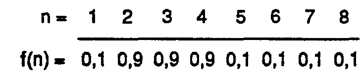
über je 4 Spurlagenabstände erstreckende Helligkeitsprofile der Fahrbahnabschnitte dar, über denen sich die Fahrzeuge FZ, FZ' gerade befinden. Andererseits ergeben dieden 16 Spurlagen SL1 SL16 entsprechenden Helligkeitswerte - nach zweckmässiger Umformung sowie Normierung gemäss nachfolgender Formel 3 folgendes Soll-Werteset:Dieses SOLL-Werteset
ist im Rechner 17 gespeichert und stellt ein normiertes Helligkeitsprofil der Fahrbahn dar, das sich beidseits der Passivspur-Mittellinie 10 inQuerrichtung über je 8 Spurlagenabstände erstreckt.
- for vehicle FZ: (centered lane position) for vehicle FZ ': (decentred lane position)These two sets of actual values represent two brightness profiles of the lane sections, over which the vehicle
longitudinal center axis 7 extends over 4 lane spacings, above which the vehicles FZ, FZ 'are currently located. On the other hand, the brightness values corresponding to the 16 track positions SL 1 SL 16 - after appropriate reshaping and standardization according to the following formula 3 - result in the following set of values:This TARGET value set is stored in thecomputer 17 and represents a normalized brightness profile of the roadway, which extends on both sides of the passivelane center line 10 in the transverse direction over 8 lane spacings each.
Zur Bestimmung der Spurlage stellt das Fahrzeug FZ fest, welcher Bereich des SOLL-Helligkeitsprofiles am besten mit dem gemessenen IST-Helligkeitsprofil übereinstimmt. Die Mittellage dieses Bereiches entspricht dann der SpurLage des Fahrzeuges FZ.To determine the lane position, the vehicle FZ determines which area of the TARGET brightness profile best matches the measured ACTUAL brightness profile. The center position of this area then corresponds to the track position of the vehicle FZ.
Rechnerisch wird die beste Übereinstimmung der beiden Helligkeitsprofile durch Kreuzkorrelation des IST-Wertesets mit dem SOLL-Werteset ermittelt. In unserem Fall sei die Kreuzkorrelation wie folgt definierte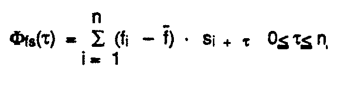
- mit dem Mittelwert der n IST-Messwerte f;

- und unter der Voraussetzung dass der Mittelwert der 2n SOLL-Werte si gleich Null ist

- Nach Durchführung einer Berechnung nach Formel 1 liegt die Kreuzkorrelationsfunktion Φis(τ) zwischen n Sensorwerten und 2n Spurlagenwerten in der Form von n + 1 Stützwerten vor.
- with the mean value of the n actual measured values f;
- and provided that the mean value of the 2n TARGET values s i is zero
- After performing a calculation according to
Formula 1, the cross-correlation function Φ is (τ) between n sensor values and 2n tracking values is available in the form of n + 1 support values.
Für die Spurlagen der beiden Fahrzeuge FZ, FZ' in Fig. 2a ergeben sich aufgrund der vorgenannten Wertesets für fn' fn' und sn die in Fig. 3a dargestellten Kreuzkorrelationsfunktionen Φis(τ) und Φ'is(τ). Vorerst ist festzuhalten, dass es sich dabei, je nach der Grösse des Abstandes d um diskrete bzw. pseudo-kontinuierliche Funktionen handelt. Im weitem ist er sichtlich, dass die Spurlagen der Fahrzeuge FZ, FZ' durch die Maxima der zugehörigen Kreuzkorrelationsfunktionen Φis(τ) und Φ'is(τ) gegeben sind. Es gilt demnach, als nächstes ein einfaches rechnerisches Verfahren zur Bestimmung des Maximums der Kreuzkorrelationsfunktion Φis(τ) anzugeben.For the lane positions of the two vehicles FZ, FZ 'in FIG. 2a, based on the aforementioned value sets for fn' fn 'and sn are the cross-correlation functions Φis (τ) and Φ'is (τ) shown in FIG. 3a. For the time being, it should be noted that, depending on the size of the distance d, these are discrete or pseudo-continuous functions. To a large extent, it is evident that the track positions of the vehicles FZ, FZ 'are given by the maxima of the associated cross-correlation functions Φ is (τ) and Φ'is (τ). The next step is to specify a simple computational method for determining the maximum of the cross-correlation function Φis (τ).
Die im vorliegenden Ausführungsbeispiel der Erfindung vorgesehene Verwendung von 8 Spursensoren mit gegenseitigem Abstand d stellt einen Kompromiss dar, um insbesondere den messtechnischen Aufwand klein zu halten. Dies bedingt eine diskrete Kreuzkorrektionsfunktion Φis(t), welche die Spurlage eines Fahrzeuges nur im Rahmen des durch den Abstand d gegebenen Rasters erfassen kann, d. h. nur wenn die Fahrzeuglage mit einer Spurlage zusammenfällt. Andererseits wird das Fahrzeug aber mit weit grösserer Wahrscheinlichkeit ausserhalb des Rasters fallende Spurlage einnehmen, welche für die Bedürfnisse der Spurführung aus regelungstechnischen Gründen mit hoher Auflösung erfasst werden müssen. Die diskrete, 9 Stützwerte aufweisende Kreuzkorrelationsfunktion wird deshalb durch Interpolation der fehlenden Funktionswerte in eine kontinuierliche Funktion umgewandelt, wie man sie mit unendlich vielen Spursensoren auch erhalten würde. Die vollständige Lösung dieser Aufgabe, nämlich
- - Aufstellen eines Polynoms n-ter Ordnung durch die n + 1 Stützwerte
- - Ableiten dieses Polynoms
- - Berechnung der n -1 Wurzeln des Ableitungspolynoms
- - Suche der mit dem absoluten Maximum im Definitionsbereich übereinstimmenden Wurzel ist für den vorgesehenen Einsatzzweck zu rechenintensiv, da bei schneller Fahrt (
bis 1,5 m/s) pro Rechenzyklus nur wenige Millisekunden zur Verfügung stehen.
- - Setting up an n-order polynomial using the n + 1 base values
- - Derive this polynomial
- - Calculation of the n -1 roots of the derivative polynomial
- - Searching for the root corresponding to the absolute maximum in the definition area is too computationally intensive for the intended purpose, since only a few milliseconds are available per computing cycle when traveling at high speeds (up to 1.5 m / s).
Es wird deshalb ein anderes Verfahren verwendet, welches, bei vertretbarem Aufwand, sehr gute Ergebnisse liefert. Dabei geht man von der Erkenntnis aus, dass die Kreuzkorrelationsfunktion nur im Bereiche ihres Maximums einen kontinuierlichen Verlauf aufweisen muss, da nur dieser Bereich zur Ermittlung der Spurlage des Fahrzeuges von Bedeutung ist. Dieses neue Verfahren enthält die folgenden drei Schritte:
- 1) Von den n + 1 Stützwerten wird das Maximum gesucht (= M).
- 2)
Ein Polynom 2. Grades wird durch diesen Punkt und seine beiden Nachbarn links und rechts gelegt. - 3) Die Ableitung dieses Polynoms
ist eine Funktion 1. Grades (Gerade), deren Nulldurchgang einfach bestimmbar ist. Da die drei bestimmenden Stützwerte ein Maximum enthalten, muss der Nulldurchgang der Ableitung auch einem Funktionsmaximum entsprechen.
- 1) The maximum of the n + 1 base values is sought (= M).
- 2) A 2nd degree polynomial is placed through this point and its two neighbors on the left and right.
- 3) The derivation of this polynomial is a function of the 1st degree (straight line), the zero crossing of which can be easily determined. Since the three determining base values contain a maximum, the zero crossing of the derivative must also correspond to a functional maximum.
Diese Verfahrens-Schritte werden nachfolgend im Detail erklärt:These process steps are explained in detail below:
Ist die Stützstelle M mit dem maximalen Funktionswert gefunden, muss sichergestellt werden, dass links ein Wert M -1, rechts ein Wert M + 1 vorhanden ist. Liegt aber M auf 1 oder n + 1, so wird das Maximum als gefunden betrachtet (1 bzw. n + 1). Falls die drei Funktionswerte auf einer Geraden liegen, wird anstelle von Schritt 2 und 3, eine spezielle Behandlung durchgeführt.If the support point M with the maximum function value is found, it must be ensured that a value M -1 is present on the left and a value M + 1 is present on the right. However, if M is 1 or n + 1, the maximum is considered to be found (1 or n + 1). If the three function values lie on a straight line, a special treatment is carried out instead of
-
Es wird das folgende Polynom aufgestellt:


-
Damit wird

-
Mit den Beziehungen:


-
sind die beiden Polynom-Koeffizienten a1 und a2 zu bestimmen:


- womit der 2. Schritt abgeschlossen ist.which completes the 2nd step.
Es wird die Ableitung des Polynoms gebildet:
- Mit Null-Setzen und nach m Auflösen erhält man

- In (11) für a1 und a2 Formel (8) und (9) eingesetzt:


- mit m im Bereich: -1 < / - m < / - 1.
- With zeroing and after m dissolving you get
- Used in (11) for a 1 and a 2 formulas (8) and (9):
- with m in the range: -1 </ - m </ - 1.
Das Ergebnis m ist der interpolierte Ort des Maximums der Kreuzkorrelationsfunktion bezogen auf den Ort M des Maximal-Stützwertes, womit der 3. Schritt abgeschlossen ist.The result m is the interpolated location of the maximum of the cross-correlation function in relation to the location M of the maximum base value, which completes the third step.
Die gesuchte Abweichung As der Spursensoren SS1...SSe gegenüber der Spurmitte kann nun wie folgt ermittelt werden:
Falls die drei Funktionswerte Φ(M- 1), Φ(M) und Φ(M + 1) auf einer Geraden liegen, wird der Nenner in (12) zu Null. Dieser spezielle Fall ist je nach Steigung der Geraden gesondert zu behandeln:
- 1)
Alle 3 Punkte weisen denselben Funktionswert auf, die Steigung der Geraden ist Null: Das Maximum liegt bei M und somit m - 0 - 2)
Die 3 Punkte weisen unterschiedliche Funktionswerte auf, das Maximum liegt beim höchsten der beiden äusseren Werte, ist die Steigung positiv, liegt das Maximum bei M + 1 und somit m - 1 negativ, liegt das Maximum bei M -1 und somit m = -1
- 1) All 3 points have the same function value, the slope of the straight line is zero: the maximum is M and thus m - 0
- 2) The 3 points have different function values, the maximum is at the highest of the two outer values, the slope is positive, the maximum is M + 1 and thus m - 1 negative, the maximum is M -1 and thus m = -1
Für die Funktion als Passivspur-Steursystem gemäss Fig. 5 werden an bestimmten Stellen des Streckennetzes Informationen benötigt, damit das Fahrzeug (FZ) an der rechten Stelle eine bestimmte Funktion ausführt, wie z. B. Anhalten, Verzweigen, Lastübergabe, Geschwindigkeit reduzieren usw. Bei mit Prozessoren ausgerüsteten Fahrzeugen sind zusätzlich Informationen erforderlich, wie z. B. Orts- oder Streckenbezeichnungen, Übergabeplatz-Nummern usw., um einen möglichst autonomen, von ortsfesten Einrichtungen unabhängigen Betrieb zu gewährleisten. Diese Informationen, die meist aus mehreren Bits - einem Datenwort - bestehen und für die eine möglichst grosse Ortsgenauigkeit verlangt ist, sind im Strichcode (28) encodiert. Dieser wird von den Codesensoren CS1...CS5 während der Fahrt oder im Stillstand gelesen und die so gewonnene Information der Fahrzeugsteuerung zugeleitet. Aus Gründen des praktischen Einsatzes ist die Anzahl der im Strichcode 28 enthaltenen dünnen (logisch "0") und dicken (logisch "1") Codestreifen 31 begrenzt. Im vorliegenden Ausführungsbeispiel der Erfindung werden pro Datenwort 1 bis 16 Nutzbit und bis zu 5 zusätzliche Korrektur- bzw. Redundanzbit verwendet. Die Anzahl der Nutzbit wird je nach Anwendung festgelegt und bleibt innerhalb einer Anlage konstant.For the function as a passive lane control system according to FIG. 5, information is required at certain points in the route network so that the vehicle (FZ) performs a certain function in the right place, such as, for example, B. Stopping, branching, load transfer, reducing speed, etc. In vehicles equipped with processors, additional information is required, such as. B. place or route names, transfer location numbers, etc., in order to ensure as autonomous as possible, independent of fixed facilities operation. This information, which usually consists of several bits - a data word - and for which the greatest possible spatial accuracy is required, is encoded in the bar code (28). This is read by the code sensors CS 1 ... CS 5 while driving or at a standstill and the information obtained in this way is fed to the vehicle control system. For reasons of practical use, the number of thin (logical "0") and thick (logical "1") code strips 31 contained in
Strichcodelesen erfolgt durch die 3 hintereinander angeordneten Codesensoren CS1, CS2 und CS4 und ist auch bei Fahrzeugstillstand oder Pendelbewegungen über dem Code möglich. Durch die Verwendung von 3 Codelesesensoren wird ein Pendeln auf den Codestreifen 31 mit Amplituden bis 5 mm erkannt und eine Mehrfachauswertung des gleichen Codestreifens 31 ausgeschlossen. Mit den Codesensoren CS3 und CSs wird das Codelesen initialisiert. Weil kein Strobsignal benötigt wird, kann der Lesekopf 21 mit den Codesensoren CS1...CS5 bis +/- 30° schräg über den Strichcode 28 geführt werden.Barcode reading is carried out by the 3 consecutively arranged code sensors CS 1 , CS 2 and CS 4 and is also possible with the vehicle at a standstill or with pendulum movements above the code. By using 3 code reading sensors, an oscillation on the
Ein Codestreifen 31 für logisch "0" wird dadurch erkannt, dass die Codesensoren CS1, CS2 und CS4 abhängig vom vorherigen Zustand in einer von der Leserichtung abhängigen Kombination auf "Sensor-Eins"-Zustand übergehen. Ein Codestreifen 31 für logisch "1" wird dadurch erkannt, dass die Codesensoren CS1, CS2 und CS4 unabhängig vom vorherigen Zustand auf "Sensor-Eins"-Zustand übergehen. Beginn oder Ende des Codes wird durch einen markanten Unterbruch 44, 44' des reflektierenden Materiales erzeugt, wodurch während einer längeren Periode sämtliche Sensoren, also Codelese- und Initialisierungs-Sensoren in den "Sensor-Null"-Zustand übergehen. Der Abstand zwischen den Codestreifen 31 ist so gewählt, dass keiner der obigen Zustände für logisch "0", logisch "1" sowie Beginn oder Ende des Codes eintreten kann. Es ist immer mindestens einer der 3 Codelesesensoren CS1 CS2, CS4 auf "Sensor-Eins"-Zustand.A
Der wirtschaftliche Einsatz des erfindungsgemässen Passivspur-Systems wird aber eindeutig bei seiner gleichzeitigen Verwendung zur Spurführung und Funktionssteuerung erzielt. Dabei ist die Passivspur 9 zweifach genutzt, nämlich von den Spursensoren SS1...SS8 als Leitlinie und von den Codesensoren CS1...CS5 als Informationsquelle. Auch wird der Strichcode 28, zusammen mit seiner eigentlichen Funktion für die Funktionssteuerung, gleichzeitig zur Spurführung eingesetzt. Obwohl die reflektierenden Codestreifen 31 einen geringeren Helligkeitsmittelwert aufweisen als die reguläre Passivspur 9 ist ihr Kontrast für die Spurführung ausreichend.However, the economical use of the passive track system according to the invention is clearly achieved with its simultaneous use for tracking and function control. The
Claims (12)
Priority Applications (1)
| Application Number | Priority Date | Filing Date | Title |
|---|---|---|---|
| AT86100908T ATE48482T1 (en) | 1985-03-15 | 1986-01-23 | PASSIVE TRACK SYSTEM FOR GUIDANCE AND CONTROL OF DRIVERLESS TRANSPORT AND ASSEMBLY UNITS. |
Applications Claiming Priority (2)
| Application Number | Priority Date | Filing Date | Title |
|---|---|---|---|
| CH1173/85A CH668655A5 (en) | 1985-03-15 | 1985-03-15 | PASSIVE TRACK DEVICE FOR GUIDING AND CONTROLLING DRIVERLESS TRANSPORT AND ASSEMBLY UNITS. |
| CH1173/85 | 1985-03-15 |
Publications (2)
| Publication Number | Publication Date |
|---|---|
| EP0195191A1 EP0195191A1 (en) | 1986-09-24 |
| EP0195191B1 true EP0195191B1 (en) | 1989-12-06 |
Family
ID=4204204
Family Applications (1)
| Application Number | Title | Priority Date | Filing Date |
|---|---|---|---|
| EP86100908A Expired EP0195191B1 (en) | 1985-03-15 | 1986-01-23 | Passive mark system for driving and controlling driverless carriage and assembly units |
Country Status (9)
| Country | Link |
|---|---|
| US (1) | US4777601A (en) |
| EP (1) | EP0195191B1 (en) |
| JP (1) | JPS61213905A (en) |
| AT (1) | ATE48482T1 (en) |
| CA (1) | CA1264490A (en) |
| CH (1) | CH668655A5 (en) |
| DE (1) | DE3667343D1 (en) |
| ES (1) | ES8701392A1 (en) |
| FI (1) | FI88344C (en) |
Families Citing this family (66)
| Publication number | Priority date | Publication date | Assignee | Title |
|---|---|---|---|---|
| FR2610427B1 (en) * | 1987-02-04 | 1995-09-29 | Protee | SYSTEM AND METHOD FOR MONITORING THE RUNNING OF A SELF-CONTAINED VEHICLE |
| EP0290634A1 (en) * | 1987-05-09 | 1988-11-17 | Carl Schenck Ag | Method of guiding a free movable vehicle without driver |
| US5002145A (en) * | 1988-01-29 | 1991-03-26 | Nec Corporation | Method and apparatus for controlling automated guided vehicle |
| JPH07120194B2 (en) * | 1988-03-31 | 1995-12-20 | 株式会社椿本チエイン | Driving control method and apparatus for automatic guided vehicle |
| US4942531A (en) * | 1988-05-16 | 1990-07-17 | Bell & Howell Company | Self-adapting signal detector with digital outputs |
| EP0374294A1 (en) * | 1988-12-22 | 1990-06-27 | Siemens Aktiengesellschaft | Information transmission device to a track-bound vehicle |
| US5066854A (en) * | 1989-02-16 | 1991-11-19 | Rieter Machine Works Ltd. | Method of and apparatus for guiding a self-steering vehicle along an optical guideway |
| US4990841A (en) * | 1989-09-19 | 1991-02-05 | Apogee Robotics | Magnetically guided vehicle |
| US5111401A (en) * | 1990-05-19 | 1992-05-05 | The United States Of America As Represented By The Secretary Of The Navy | Navigational control system for an autonomous vehicle |
| US5216605A (en) * | 1990-06-28 | 1993-06-01 | Eaton-Kenway, Inc. | Update marker system for navigation of an automatic guided vehicle |
| US5281901A (en) * | 1990-12-03 | 1994-01-25 | Eaton-Kenway, Inc. | Downward compatible AGV system and methods |
| US5187664A (en) * | 1990-11-27 | 1993-02-16 | Eaton-Kenway, Inc. | Proportional position-sensing system for an automatic guided vehicle |
| US5191528A (en) * | 1990-06-28 | 1993-03-02 | Eaton-Kenway, Inc. | Update marker system for naviagtion of an automatic guided vehicle |
| CA2053028C (en) * | 1990-10-23 | 1996-04-09 | Hideichi Tanizawa | Carriage running control system |
| US5127486A (en) * | 1990-11-23 | 1992-07-07 | Eaton-Kenway, Inc. | System for sensing arrival of an automatic guided vehicle at a wire |
| US5175415A (en) * | 1990-11-27 | 1992-12-29 | Eaton-Kenway, Inc. | Combination drive-wheel mechanism and travel-sensor mechanism |
| US5539646A (en) * | 1993-10-26 | 1996-07-23 | Hk Systems Inc. | Method and apparatus for an AGV inertial table having an angular rate sensor and a voltage controlled oscillator |
| JP3330710B2 (en) * | 1993-12-30 | 2002-09-30 | 本田技研工業株式会社 | Mobile robot position detection and control device |
| US5961571A (en) * | 1994-12-27 | 1999-10-05 | Siemens Corporated Research, Inc | Method and apparatus for automatically tracking the location of vehicles |
| US5991674A (en) * | 1996-05-02 | 1999-11-23 | Chrysler Corporation | Floor shifter linkage for robotic control of vehicle |
| US5865266A (en) * | 1996-05-02 | 1999-02-02 | Chrysler Corporation | Steering wheel linkage for robotic system for automated durability road (ADR) facility |
| US5913945A (en) * | 1996-05-02 | 1999-06-22 | Daimlerchrysler Corporation | Pedal linkage for robotic control of vehicle |
| US5821718A (en) * | 1996-05-07 | 1998-10-13 | Chrysler Corporation | Robotic system for automated durability road (ADR) facility |
| US6141620A (en) * | 1996-09-03 | 2000-10-31 | Chrysler Corporation | Vehicle control system for automated durability road (ADR) facility |
| US5906647A (en) * | 1996-09-03 | 1999-05-25 | Chrysler Corporation | Vehicle mounted guidance antenna for automated durability road (ADR) facility |
| US6061613A (en) * | 1996-09-03 | 2000-05-09 | Chrysler Corporation | Base station for automated durability road (ADR) facility |
| US5938705A (en) * | 1996-09-03 | 1999-08-17 | Chrysler Corporation | Vehicle controller (VCON) for automated durability road (ADR) facility |
| US5867089A (en) * | 1996-09-03 | 1999-02-02 | Chrysler Corporation | Base-to-remotely controlled vehicle communications for automated durability road (ADR) facility |
| US5908454A (en) * | 1996-09-03 | 1999-06-01 | Chrysler Corporation | Operator interface for automated durability road (ADR) facility |
| FR2762085B1 (en) * | 1997-04-09 | 1999-06-04 | Cilas | METHOD FOR DETERMINING THE POSITION OF A SENSOR RELATIVE TO A LONGITUDINAL STRIP, SENSOR FOR IMPLEMENTING SAID METHOD AND APPLICATION |
| DE19814848B4 (en) * | 1998-04-02 | 2006-05-04 | Volkswagen Ag | Simulation arrangement for motor vehicle accidents and method for the simulation of motor vehicle accidents |
| US6453237B1 (en) * | 1999-04-23 | 2002-09-17 | Global Locate, Inc. | Method and apparatus for locating and providing services to mobile devices |
| KR20010044053A (en) * | 2000-06-23 | 2001-06-05 | 유재춘 | apparatus for sensing traveling status of mobile robot |
| GB2374797A (en) * | 2001-04-23 | 2002-10-30 | Paolo Niccolai | Self propelled and guided household or other indoor appliance |
| JP2002321699A (en) * | 2001-04-27 | 2002-11-05 | Mitsubishi Heavy Ind Ltd | Air cargo carrying system |
| NL1019191C2 (en) * | 2001-10-18 | 2003-04-23 | Frog Navigation Systems B V | Vehicle and method of driving thereof. |
| ES2268122T3 (en) | 2001-12-12 | 2007-03-16 | Jervis B. Webb International Company | SYSTEM AND PROCEDURE FOR GUIDING VEHICLES WITHOUT DRIVER. |
| GB2384691A (en) * | 2002-01-29 | 2003-08-06 | Paolo Niccolai | Self propelled and guided floor cleaner or transport device |
| US8210791B2 (en) * | 2004-05-03 | 2012-07-03 | Jervis B. Webb Company | Automatic transport loading system and method |
| US8075243B2 (en) | 2004-05-03 | 2011-12-13 | Jervis B. Webb Company | Automatic transport loading system and method |
| US7980808B2 (en) * | 2004-05-03 | 2011-07-19 | Jervis B. Webb Company | Automatic transport loading system and method |
| US8192137B2 (en) | 2004-05-03 | 2012-06-05 | Jervis B. Webb Company | Automatic transport loading system and method |
| WO2005108246A2 (en) * | 2004-05-03 | 2005-11-17 | Jervis B. Webb Company | Automatic transport loading system and method |
| DE102005024881A1 (en) * | 2005-05-31 | 2006-12-07 | Still Gmbh | Industrial truck with an electrical control unit |
| US20060276958A1 (en) * | 2005-06-02 | 2006-12-07 | Jervis B. Webb Company | Inertial navigational guidance system for a driverless vehicle utilizing laser obstacle sensors |
| US8768558B2 (en) * | 2007-01-05 | 2014-07-01 | Agjunction Llc | Optical tracking vehicle control system and method |
| USRE48527E1 (en) * | 2007-01-05 | 2021-04-20 | Agjunction Llc | Optical tracking vehicle control system and method |
| US20110301757A1 (en) * | 2008-02-21 | 2011-12-08 | Harvest Automation, Inc. | Adaptable container handling robot with boundary sensing subsystem |
| US8915692B2 (en) | 2008-02-21 | 2014-12-23 | Harvest Automation, Inc. | Adaptable container handling system |
| US9147173B2 (en) | 2011-10-31 | 2015-09-29 | Harvest Automation, Inc. | Methods and systems for automated transportation of items between variable endpoints |
| US9702707B2 (en) * | 2011-12-22 | 2017-07-11 | AppLabz, LLC | Systems, methods, and apparatus for providing indoor navigation using optical floor sensors |
| US8937410B2 (en) | 2012-01-17 | 2015-01-20 | Harvest Automation, Inc. | Emergency stop method and system for autonomous mobile robots |
| US9726686B2 (en) * | 2012-02-03 | 2017-08-08 | Siemens Healthcare Diagnostics Inc. | Encoding scheme embedded into an automation track surface |
| CN104679004B (en) * | 2015-02-09 | 2017-07-11 | 上海交通大学 | Automatic guided vehicle and its guidance method that flexible path is combined with fixed route |
| US10683171B2 (en) | 2016-09-30 | 2020-06-16 | Staples, Inc. | Hybrid modular storage fetching system |
| CA3038898A1 (en) | 2016-09-30 | 2018-04-05 | Staples, Inc. | Hybrid modular storage fetching system |
| US10589931B2 (en) | 2016-09-30 | 2020-03-17 | Staples, Inc. | Hybrid modular storage fetching system |
| EP3399379B1 (en) * | 2017-05-05 | 2023-04-26 | Leuze electronic GmbH + Co. KG | Sensor assembly |
| US11084410B1 (en) | 2018-08-07 | 2021-08-10 | Staples, Inc. | Automated guided vehicle for transporting shelving units |
| US11590997B1 (en) | 2018-08-07 | 2023-02-28 | Staples, Inc. | Autonomous shopping cart |
| US11630447B1 (en) | 2018-08-10 | 2023-04-18 | Staples, Inc. | Automated guided vehicle for transporting objects |
| US11180069B2 (en) | 2018-12-31 | 2021-11-23 | Staples, Inc. | Automated loading of delivery vehicles using automated guided vehicles |
| US11119487B2 (en) | 2018-12-31 | 2021-09-14 | Staples, Inc. | Automated preparation of deliveries in delivery vehicles using automated guided vehicles |
| US11124401B1 (en) | 2019-03-31 | 2021-09-21 | Staples, Inc. | Automated loading of delivery vehicles |
| US11221631B2 (en) * | 2019-04-24 | 2022-01-11 | Innovation First, Inc. | Performance arena for robots with position location system |
| DE102020200894A1 (en) | 2020-01-27 | 2021-07-29 | Zf Friedrichshafen Ag | Coding of information in road markings |
Family Cites Families (17)
| Publication number | Priority date | Publication date | Assignee | Title |
|---|---|---|---|---|
| US3738443A (en) * | 1969-11-28 | 1973-06-12 | M Kubo | Control system for the travel of a goods trolley |
| JPS49110020A (en) * | 1973-02-21 | 1974-10-19 | ||
| JPS5610643B2 (en) * | 1973-12-17 | 1981-03-10 | ||
| US3935922A (en) * | 1974-07-16 | 1976-02-03 | Lear Siegler, Inc. | Vehicle guidance mechanism |
| US4020918A (en) * | 1975-12-31 | 1977-05-03 | Lear Siegler, Inc. | Manually operable automatically controlled vehicle with power steering |
| US4003445A (en) * | 1976-02-12 | 1977-01-18 | Lear Siegler, Inc. | Code circuitry for a vehicle guidance mechanism |
| US4139862A (en) * | 1977-09-08 | 1979-02-13 | Nasa | Interactive color display for multispectral imagery using correlation clustering |
| FR2406245A1 (en) * | 1977-10-13 | 1979-05-11 | Matra Engins | Automatic guidance for vehicle in transport installation - employs receiver to sense light reflected from emitter via mirror |
| US4278142A (en) * | 1978-05-08 | 1981-07-14 | Agency Of Industrial Science And Technology | Automatic guidance system for vehicles |
| FR2443713A1 (en) * | 1978-12-06 | 1980-07-04 | Matra | AUTOMATIC VEHICLE INSTALLATION |
| US4307791A (en) * | 1978-12-06 | 1981-12-29 | Bell & Howell Company | Line follower vehicle with scanning head |
| JPS5911922B2 (en) * | 1980-08-13 | 1984-03-19 | 株式会社日立製作所 | Unmanned conveyance device |
| SE423839B (en) * | 1980-10-02 | 1982-06-07 | Volvo Ab | SET AND DEVICE FOR STEERING A STEERABLE WHEEL VEHICLE |
| SE423840B (en) * | 1980-10-02 | 1982-06-07 | Volvo Ab | VIEW THROUGH A WHEEL-DRIVED DRIVE VEHICLE TO PROVIDE AN UPDATE |
| JPS59112312A (en) * | 1982-12-20 | 1984-06-28 | Nippon Yusoki Co Ltd | Guiding band of unmanned carrier car |
| JPS6063618A (en) * | 1983-09-17 | 1985-04-12 | Tsubakimoto Chain Co | Run controlling method of unmanned running car |
| JPS61204713A (en) * | 1985-03-07 | 1986-09-10 | Murata Mach Ltd | Guidance system for unmanned running car |
-
1985
- 1985-03-15 CH CH1173/85A patent/CH668655A5/en not_active IP Right Cessation
-
1986
- 1986-01-23 AT AT86100908T patent/ATE48482T1/en active
- 1986-01-23 ES ES551163A patent/ES8701392A1/en not_active Expired
- 1986-01-23 DE DE8686100908T patent/DE3667343D1/en not_active Expired - Fee Related
- 1986-01-23 EP EP86100908A patent/EP0195191B1/en not_active Expired
- 1986-02-27 CA CA000502828A patent/CA1264490A/en not_active Expired - Fee Related
- 1986-03-03 US US06/835,248 patent/US4777601A/en not_active Expired - Fee Related
- 1986-03-06 FI FI860938A patent/FI88344C/en not_active IP Right Cessation
- 1986-03-14 JP JP61056746A patent/JPS61213905A/en active Pending
Also Published As
| Publication number | Publication date |
|---|---|
| CH668655A5 (en) | 1989-01-13 |
| ES551163A0 (en) | 1986-11-16 |
| CA1264490A (en) | 1990-01-16 |
| ATE48482T1 (en) | 1989-12-15 |
| FI860938A0 (en) | 1986-03-06 |
| FI88344C (en) | 1993-04-26 |
| FI860938A (en) | 1986-09-16 |
| EP0195191A1 (en) | 1986-09-24 |
| ES8701392A1 (en) | 1986-11-16 |
| DE3667343D1 (en) | 1990-01-11 |
| FI88344B (en) | 1993-01-15 |
| JPS61213905A (en) | 1986-09-22 |
| US4777601A (en) | 1988-10-11 |
Similar Documents
| Publication | Publication Date | Title |
|---|---|---|
| EP0195191B1 (en) | Passive mark system for driving and controlling driverless carriage and assembly units | |
| DE3787003T2 (en) | STEERING DEVICE FOR BODIES MOVING UNMANNED. | |
| DE4013168C2 (en) | Driving control method and driving control device for a mobile robot system | |
| DE3889474T2 (en) | Navigation system and method for operating an autonomous vehicle. | |
| EP0388390B1 (en) | Incremental measuring system | |
| DE3144334C2 (en) | Position measuring device with reference marks | |
| DE102007029299B4 (en) | Optical sensor for positioning tasks | |
| WO2000010062A2 (en) | Method and device for determining a path around a defined reference position | |
| CH683703A5 (en) | Method for track surveying. | |
| EP0954773A1 (en) | Method and device for docking an autonomous mobile unit | |
| DE2949204A1 (en) | SYSTEM WITH AUTOMATICALLY CONTROLLED VEHICLES | |
| EP0970390A1 (en) | Method for determining the vertical distance between an object and a device with a variable position | |
| DE3332615C2 (en) | Optically guided vehicle | |
| WO1986003612A1 (en) | Device for spacing apart vehicles held on a track | |
| EP0378528B1 (en) | Process for steering a self-propelled vehicle and self-propelled vehicle | |
| EP3401702A1 (en) | Sensor system | |
| DE102019116892A1 (en) | Lane event anticipation through LiDAR road boundary detection | |
| EP0374290A1 (en) | Railway vehicle | |
| DE3828447C2 (en) | Optical guidance device for driverless transport systems | |
| DE3930109C1 (en) | ||
| WO2000003200A2 (en) | Device and method for determining a spatial position of an object | |
| EP0937965B1 (en) | Positioning system | |
| DE68920564T2 (en) | Apparatus for the optical profiling of an object. | |
| EP0261450A1 (en) | Guiding system for individual traffic | |
| DE19823260A1 (en) | Driverless transport system for vehicles with arbitrary wheel configuration |
Legal Events
| Date | Code | Title | Description |
|---|---|---|---|
| PUAI | Public reference made under article 153(3) epc to a published international application that has entered the european phase |
Free format text: ORIGINAL CODE: 0009012 |
|
| AK | Designated contracting states |
Kind code of ref document: A1 Designated state(s): AT BE CH DE FR GB IT LI NL SE |
|
| RAP1 | Party data changed (applicant data changed or rights of an application transferred) |
Owner name: JD-TECHNOLOGIE AG |
|
| 17P | Request for examination filed |
Effective date: 19870304 |
|
| ITCL | It: translation for ep claims filed |
Representative=s name: FUMERO BREVETTI S.N.C. |
|
| EL | Fr: translation of claims filed | ||
| 17Q | First examination report despatched |
Effective date: 19880711 |
|
| GRAA | (expected) grant |
Free format text: ORIGINAL CODE: 0009210 |
|
| ITF | It: translation for a ep patent filed | ||
| AK | Designated contracting states |
Kind code of ref document: B1 Designated state(s): AT BE CH DE FR GB IT LI NL SE |
|
| PG25 | Lapsed in a contracting state [announced via postgrant information from national office to epo] |
Ref country code: NL Effective date: 19891206 Ref country code: BE Effective date: 19891206 |
|
| REF | Corresponds to: |
Ref document number: 48482 Country of ref document: AT Date of ref document: 19891215 Kind code of ref document: T |
|
| ET | Fr: translation filed | ||
| REF | Corresponds to: |
Ref document number: 3667343 Country of ref document: DE Date of ref document: 19900111 |
|
| GBT | Gb: translation of ep patent filed (gb section 77(6)(a)/1977) | ||
| NLV1 | Nl: lapsed or annulled due to failure to fulfill the requirements of art. 29p and 29m of the patents act | ||
| PLBE | No opposition filed within time limit |
Free format text: ORIGINAL CODE: 0009261 |
|
| STAA | Information on the status of an ep patent application or granted ep patent |
Free format text: STATUS: NO OPPOSITION FILED WITHIN TIME LIMIT |
|
| 26N | No opposition filed | ||
| REG | Reference to a national code |
Ref country code: CH Ref legal event code: PUE Owner name: DIGITRON AG |
|
| ITPR | It: changes in ownership of a european patent |
Owner name: CESSIONE;DIGITRON AG |
|
| REG | Reference to a national code |
Ref country code: GB Ref legal event code: 732 |
|
| REG | Reference to a national code |
Ref country code: FR Ref legal event code: TP |
|
| ITTA | It: last paid annual fee | ||
| REG | Reference to a national code |
Ref country code: CH Ref legal event code: PFA Free format text: DIGITRON AG |
|
| ITPR | It: changes in ownership of a european patent |
Owner name: FUSIONI;SPRECHER + SCHUH AUTOMATION |
|
| REG | Reference to a national code |
Ref country code: FR Ref legal event code: CA |
|
| REG | Reference to a national code |
Ref country code: GB Ref legal event code: 732E |
|
| EAL | Se: european patent in force in sweden |
Ref document number: 86100908.2 |
|
| PGFP | Annual fee paid to national office [announced via postgrant information from national office to epo] |
Ref country code: CH Payment date: 19951222 Year of fee payment: 11 |
|
| PGFP | Annual fee paid to national office [announced via postgrant information from national office to epo] |
Ref country code: SE Payment date: 19960115 Year of fee payment: 11 Ref country code: GB Payment date: 19960115 Year of fee payment: 11 |
|
| PGFP | Annual fee paid to national office [announced via postgrant information from national office to epo] |
Ref country code: FR Payment date: 19960131 Year of fee payment: 11 Ref country code: DE Payment date: 19960131 Year of fee payment: 11 Ref country code: AT Payment date: 19960131 Year of fee payment: 11 |
|
| PG25 | Lapsed in a contracting state [announced via postgrant information from national office to epo] |
Ref country code: GB Effective date: 19970123 Ref country code: AT Effective date: 19970123 |
|
| PG25 | Lapsed in a contracting state [announced via postgrant information from national office to epo] |
Ref country code: SE Effective date: 19970124 |
|
| PG25 | Lapsed in a contracting state [announced via postgrant information from national office to epo] |
Ref country code: LI Effective date: 19970131 Ref country code: CH Effective date: 19970131 |
|
| GBPC | Gb: european patent ceased through non-payment of renewal fee |
Effective date: 19970123 |
|
| REG | Reference to a national code |
Ref country code: CH Ref legal event code: PL |
|
| PG25 | Lapsed in a contracting state [announced via postgrant information from national office to epo] |
Ref country code: FR Effective date: 19970930 |
|
| PG25 | Lapsed in a contracting state [announced via postgrant information from national office to epo] |
Ref country code: DE Effective date: 19971001 |
|
| EUG | Se: european patent has lapsed |
Ref document number: 86100908.2 |
|
| REG | Reference to a national code |
Ref country code: FR Ref legal event code: ST |
|
| PG25 | Lapsed in a contracting state [announced via postgrant information from national office to epo] |
Ref country code: IT Free format text: LAPSE BECAUSE OF NON-PAYMENT OF DUE FEES;WARNING: LAPSES OF ITALIAN PATENTS WITH EFFECTIVE DATE BEFORE 2007 MAY HAVE OCCURRED AT ANY TIME BEFORE 2007. THE CORRECT EFFECTIVE DATE MAY BE DIFFERENT FROM THE ONE RECORDED. Effective date: 20050123 |