EP0195083B1 - Türspion - Google Patents
Türspion Download PDFInfo
- Publication number
- EP0195083B1 EP0195083B1 EP85905334A EP85905334A EP0195083B1 EP 0195083 B1 EP0195083 B1 EP 0195083B1 EP 85905334 A EP85905334 A EP 85905334A EP 85905334 A EP85905334 A EP 85905334A EP 0195083 B1 EP0195083 B1 EP 0195083B1
- Authority
- EP
- European Patent Office
- Prior art keywords
- housing
- screen
- partition
- viewer according
- security
- Prior art date
- Legal status (The legal status is an assumption and is not a legal conclusion. Google has not performed a legal analysis and makes no representation as to the accuracy of the status listed.)
- Expired
Links
- 238000005192 partition Methods 0.000 claims abstract description 26
- 239000005337 ground glass Substances 0.000 claims description 5
- 230000003287 optical effect Effects 0.000 claims description 5
- 230000001681 protective effect Effects 0.000 claims description 4
- 239000002184 metal Substances 0.000 claims description 3
- 239000002991 molded plastic Substances 0.000 claims description 3
- 238000004026 adhesive bonding Methods 0.000 claims 2
- 238000000034 method Methods 0.000 claims 2
- 238000003780 insertion Methods 0.000 claims 1
- 230000037431 insertion Effects 0.000 claims 1
- 239000011521 glass Substances 0.000 description 5
- 239000004033 plastic Substances 0.000 description 3
- 229920003023 plastic Polymers 0.000 description 3
- 239000003292 glue Substances 0.000 description 2
- 229920001651 Cyanoacrylate Polymers 0.000 description 1
- 239000000853 adhesive Substances 0.000 description 1
- 230000001070 adhesive effect Effects 0.000 description 1
- 230000015572 biosynthetic process Effects 0.000 description 1
- -1 cyanoacrylate ester Chemical class 0.000 description 1
- 238000001035 drying Methods 0.000 description 1
- 239000000463 material Substances 0.000 description 1
- 230000002093 peripheral effect Effects 0.000 description 1
- 239000005341 toughened glass Substances 0.000 description 1
Images
Classifications
-
- G—PHYSICS
- G02—OPTICS
- G02B—OPTICAL ELEMENTS, SYSTEMS OR APPARATUS
- G02B25/00—Eyepieces; Magnifying glasses
- G02B25/04—Eyepieces; Magnifying glasses affording a wide-angle view, e.g. through a spy-hole
-
- E—FIXED CONSTRUCTIONS
- E06—DOORS, WINDOWS, SHUTTERS, OR ROLLER BLINDS IN GENERAL; LADDERS
- E06B—FIXED OR MOVABLE CLOSURES FOR OPENINGS IN BUILDINGS, VEHICLES, FENCES OR LIKE ENCLOSURES IN GENERAL, e.g. DOORS, WINDOWS, BLINDS, GATES
- E06B7/00—Special arrangements or measures in connection with doors or windows
- E06B7/28—Other arrangements on doors or windows, e.g. door-plates, windows adapted to carry plants, hooks for window cleaners
- E06B7/30—Peep-holes; Devices for speaking through; Doors having windows
Definitions
- This invention relates to a security viewer to be mounted through a non-transparent partition, for example a door.
- Security viewers for doors are well known and one example is described in GB Patent Specification 1 129 121.
- This known viewer consists of a spy glass which is mounted in a hole drilled through the door and acts in the manner of a spy glass to permit a person on the inside of the door to observe callers at the door.
- a disadvantage of the known spy glass type of security viewer is that its optical system needs to provide a wide field of view and consequently the image produced is somewhat distorted so that an observer of the inside of the door may have difficulty in identifying and recognising a caller.
- the observer needs to place his or her eye against the door in order to observe the image formed by the spy glass.
- the spy glass is mounted approximately 2 meters from the base of the door and consequently cannot be readily used by the elderly and the infirm.
- a security viewer which provides an image of reduced distortion and which can be observed without the need for the observer to place his or her eye against the door.
- the security viewer comprises a housing for extending through a partition such as a door, the housing including an inlet aperture for collecting light from a first side of the partition, a screen for being observed from a second opposite side of the partition, and lens means for forming from the collected light a real image on the screen of the field of view on the first side of the partition.
- the formation of the real image on the screen has the advantage that the image of the field is observable from positions spaced from the partition so that the observer does not need to place his or her eye against the partition as in the prior art.
- the housing of the security viewer includes a tubular portion to be fitted through the hole in the partition, the tubular portion having the inlet aperture at one end thereof.
- An outer bezel is arranged to be fitted on to the end of the tubular housing portion so as to abut the partition.
- an inner bezel is movably mounted on the tubular housing portion and in use is glued in an appropriate position depending on the thickness of the door.
- the lens means comprises an even number of biconvex lenses e.g. four arranged coaxially within the tubular portion of the housing.
- the four lenses are conveniently identical and have different radii of curvature on their opposite faces.
- the face of each lens with the greatest curvature radius is arranged facing the screen but I have also found that by turning round one of the lenses, an improved image sharpness is produced.
- a protective transparent member is arranged spanning the inlet aperture. Conveniently, the protective transparent member may be held in place by means of the outer bezel.
- the screen is conveniently made of ground glass.
- the screen is 35 mm square and thus provides an image which is observable from up to 3 or 4 meters from the partition.
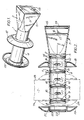
- the security viewer consists of an elongate housing 1 formed of cooperating moulded plastics parts 2, 3 typically made of ABS material.
- the housing parts 2, 3 define a tubular portion 4 and an outwardly tapered portion 5 having a common longitudinal axis that is a straight line i.e. with no bends therein, this axis defining the optical axis of the viewer.
- the tubular portion 4 in use is inserted through a hole 6 in a partition 7, typically a door of the building.
- the tubular portion 4 contains at one end thereof an inlet aperture 8 which collects light from one side of the partition from a field of view coaxial with the optical axis of the viewer.
- Lenses 9 to 12 case on a ground glass screen 13 a real image of the field determined by the light entering the inlet aperture 8.
- the housing parts 2, 3 are formed with integral annular stops 14 to receive the lenses 9 to 12, and a peripheral recess 15 to receive the ground glass screen 13.
- the two housing parts 2,3 are typically glued together and are formed with integral cooperating lugs and sockets 16, 17 to achieve alignment of the housing parts.
- the tubular housing portion 4 is cylindrical and has slidably mounted thereon an inner plastics bezel 18 which defines a circular flange bounding the periphery of the housing.
- a similar outer plastics bezel 19 is adapted to be push fitted on to the end of the cylindrical housing portion.
- the outer bezel 19 includes an opening 20 which is aligned with the inlet aperture 8.
- the opening 20 is formed with a flanged periphery 21 to receive a transparent toughened glass protective member 22.
- the member 22 covers the lens 9 to prevent it from being scratched.
- a hole is drilled through the door, typically 2 meters above the floor.
- the cylindrical housing part 4 is pushed into the hole with the inner bezel 18 already slidably fitted.
- the housing portion 4 is adjusted to the position shown in Figure 2 such that the inlet aperture 8 protrudes sufficiently to receive the outer bezel 19, with the bezel 19 abutting outer surface 7a of the door (in the position shown in hatched outline 23).
- the inner bezel 18 is then slid along the cylindrical housing part 4 until it abuts inner surface 7b of the door (i.e. in the position shown by hatched outline 23).
- the housing 1 is then removed from the door and the inner bezel 18 is glued to the cylindrical housing portion 4 using an appropriate quick drying glue for example a cyanoacrylate ester adhesive.
- the housing portion together with the glued inner bezel 18 is returned to the door and inserted into the hole 6.
- the outer bezel 19 is then glued in place using a similar glue, with the transparent member 22 being held in position by the bezel 19.
- the slidable arrangement of the inner bezel 18 has the advantage that the security viewer can be fitted to doors of different thicknesses. Moreover, the bezels 18, 19 cover any burrs and the like which may be formed when the hole 6 is drilled in the door. Also, it will be appreciated that the fixing arrangement for the viewer has the advantage that no additional screws or like intrusive fixings need to be used to locate the viewer.
- the four lenses 9 to 12 of the preferred embodiment are biconvex lenses with different radii of curvature on their opposite faces.
- the lenses are equally spaced apart by a distance of 2.7 mm.
- the faces with the least radii of curvature R all face towards the screen 13.
- the outside diameter of the cylindrical housing portion 14 is 36 mm and the overall length of the housing is 146 mm.
- the screen 13 is spaced 55 mm from the lens 12.
- the screen 13 is 35 mm square and thus provides a relatively large image which can be seen from 3 to 4 meters from the door.
- the viewer of the invention can be used with advantage in the entrance door of a domestic building and has the advantage that it is not necessary for an observer inside the door to place his or her eye against the viewer to observe a caller at the door. Instead, the real image formed on the screen 13 can be observed from some distance thus facilitating use of the viewer by the elderly and the inform, for example.
- the invention may be used in partitions other than doors.
- the invention has particular application to doors in aircraft, ships cabins, factories and offices. It can also be used in Banks, photographic darkrooms and hospitals.
- the provision of the ground glass screen has the advantage that the viewer operates in one direction only, i.e. a caller at the door cannot use the viewer to observe the inside of the dwelling.
- the housing includes a decorative metal sheath surrounding the housing parts 2, 3, so as to form a generally conical portion surrounding the tapered portion 5.
- the bezel 18 may be made of spun metal rather than plastic.
Landscapes
- Physics & Mathematics (AREA)
- Engineering & Computer Science (AREA)
- Civil Engineering (AREA)
- Structural Engineering (AREA)
- General Physics & Mathematics (AREA)
- Optics & Photonics (AREA)
- Lenses (AREA)
Claims (15)
Priority Applications (1)
| Application Number | Priority Date | Filing Date | Title |
|---|---|---|---|
| AT85905334T ATE44321T1 (de) | 1984-09-12 | 1985-09-12 | Tuerspion. |
Applications Claiming Priority (2)
| Application Number | Priority Date | Filing Date | Title |
|---|---|---|---|
| GB8423090 | 1984-09-12 | ||
| GB848423090A GB8423090D0 (en) | 1984-09-12 | 1984-09-12 | Doorcall home-eye |
Publications (2)
| Publication Number | Publication Date |
|---|---|
| EP0195083A1 EP0195083A1 (de) | 1986-09-24 |
| EP0195083B1 true EP0195083B1 (de) | 1989-06-28 |
Family
ID=10566644
Family Applications (1)
| Application Number | Title | Priority Date | Filing Date |
|---|---|---|---|
| EP85905334A Expired EP0195083B1 (de) | 1984-09-12 | 1985-09-12 | Türspion |
Country Status (6)
| Country | Link |
|---|---|
| US (1) | US4726670A (de) |
| EP (1) | EP0195083B1 (de) |
| JP (1) | JPS62500405A (de) |
| DE (1) | DE3571280D1 (de) |
| GB (1) | GB8423090D0 (de) |
| WO (1) | WO1986001908A1 (de) |
Cited By (2)
| Publication number | Priority date | Publication date | Assignee | Title |
|---|---|---|---|---|
| DE3835307A1 (de) * | 1988-08-05 | 1990-02-08 | Chul Hoon Ahn | Optisches system zum einbau in eine tuer |
| GB2413397A (en) * | 2004-04-24 | 2005-10-26 | Camdeor Technology Co Ltd | Focussing means for a video camera |
Families Citing this family (18)
| Publication number | Priority date | Publication date | Assignee | Title |
|---|---|---|---|---|
| USD307153S (en) | 1987-04-20 | 1990-04-10 | Rejan, Inc. | Viewer for a door |
| US5214533A (en) * | 1987-11-09 | 1993-05-25 | Alexandre Moracchini | Portable monocular with high magnification |
| USD310840S (en) | 1988-09-02 | 1990-09-25 | Degnan Donald E | Door viewer |
| USD330382S (en) | 1990-04-10 | 1992-10-20 | Degnan Donald E | Panoramic door viewer |
| US5550673A (en) * | 1991-11-01 | 1996-08-27 | Goldstein; Pinchas | Spyhole viewer |
| IL99941A (en) * | 1991-11-01 | 1997-02-18 | Goldstein Pinchas | Spyhole viewer |
| USD345368S (en) | 1992-07-31 | 1994-03-22 | Luxtec Corporation | Surgical telescope |
| JP3335235B2 (ja) * | 1993-10-27 | 2002-10-15 | 旭光学工業株式会社 | スコープ |
| USD365833S (en) | 1994-05-02 | 1996-01-02 | United States Marketing Corporation | Door viewer |
| USD390584S (en) | 1997-04-04 | 1998-02-10 | Layton Adam S | Novelty interior security peephole cover |
| FR2884266B1 (fr) * | 2005-04-07 | 2008-11-21 | Frederic Remaud | Element de construction de type brique ou parpaing, et assemblage de tels elements |
| RU2393516C2 (ru) * | 2007-08-09 | 2010-06-27 | Государственное образовательное учреждение высшего профессионального образования "Московский государственный университет геодезии и картографии" (МИИГАиК) | Оптическое устройство для формирования лазерного излучения в виде квазипараллельного пучка |
| US20090091618A1 (en) * | 2007-10-05 | 2009-04-09 | Anderson Leroy E | Electronic viewer for peephole |
| USD688965S1 (en) * | 2011-01-20 | 2013-09-03 | Acuvera Marketing Inc. | Digital door security viewer |
| US8733020B2 (en) | 2011-11-14 | 2014-05-27 | Kamran Khoshkish | Door viewer security cover |
| US9297200B2 (en) | 2011-11-14 | 2016-03-29 | Icu, Llc | Door viewer security cover |
| JP1595022S (de) * | 2017-05-08 | 2018-01-22 | ||
| USD920412S1 (en) * | 2018-07-13 | 2021-05-25 | Unistellar | Telescope |
Family Cites Families (14)
| Publication number | Priority date | Publication date | Assignee | Title |
|---|---|---|---|---|
| US1682139A (en) * | 1928-08-28 | View st | ||
| US2262203A (en) * | 1940-02-28 | 1941-11-11 | Louis G Redstone | Optical protective device |
| US2638810A (en) * | 1951-05-24 | 1953-05-19 | George H Berleme | Door peep observation device |
| FR1254122A (fr) * | 1960-04-12 | 1961-02-17 | Blanchard Et Jourjon | Lunette à grand champ de vision, et dispositions combinées pour constituer notamment un judas optique |
| US3434773A (en) * | 1964-07-17 | 1969-03-25 | Lorena Jean Pitchford | Aircraft landing gear viewer |
| FR1409084A (fr) * | 1964-09-25 | 1965-08-20 | Meopta Narodni Podnik | Monture pour un ensemble d'éléments optiques ou mécaniques centrés sur un axe commun |
| GB1129121A (en) * | 1965-02-05 | 1968-10-02 | Jean Charles Joseph Blosse | Improvements in and relating to optical spyglass |
| DE2254954B2 (de) * | 1972-11-10 | 1975-07-17 | Isco-Optische Werke Gmbh, 3400 Goettingen | Kunststoff-Fassung für optische Systeme |
| US3959581A (en) * | 1975-01-29 | 1976-05-25 | Zenith Radio Corporation | Self-compensating focus system for optical video playback device |
| US3973835A (en) * | 1975-05-05 | 1976-08-10 | Jimmie Miyakawa | Security viewing device |
| US4257670A (en) * | 1978-09-13 | 1981-03-24 | Legrand Daniel L | Optical peephole device insertable in thick walls for panoramic viewing therethrough |
| GB2042203B (en) * | 1979-02-15 | 1983-03-09 | Legrand D L | Optical peephole device |
| US4251127A (en) * | 1979-06-15 | 1981-02-17 | Takeyoshi Yamaguchi | Wide-angle door viewer |
| DE3240158A1 (de) * | 1982-10-29 | 1984-06-20 | Stephan 7570 Baden-Baden Lutze | Geraet zur betrachtung fotografischer aufnahmen |
-
1984
- 1984-09-12 GB GB848423090A patent/GB8423090D0/en active Pending
-
1985
- 1985-09-12 JP JP60504739A patent/JPS62500405A/ja active Pending
- 1985-09-12 DE DE8585905334T patent/DE3571280D1/de not_active Expired
- 1985-09-12 EP EP85905334A patent/EP0195083B1/de not_active Expired
- 1985-09-12 WO PCT/GB1985/000417 patent/WO1986001908A1/en not_active Ceased
- 1985-09-12 US US06/862,104 patent/US4726670A/en not_active Expired - Fee Related
Cited By (2)
| Publication number | Priority date | Publication date | Assignee | Title |
|---|---|---|---|---|
| DE3835307A1 (de) * | 1988-08-05 | 1990-02-08 | Chul Hoon Ahn | Optisches system zum einbau in eine tuer |
| GB2413397A (en) * | 2004-04-24 | 2005-10-26 | Camdeor Technology Co Ltd | Focussing means for a video camera |
Also Published As
| Publication number | Publication date |
|---|---|
| GB8423090D0 (en) | 1984-10-17 |
| DE3571280D1 (en) | 1989-08-03 |
| EP0195083A1 (de) | 1986-09-24 |
| WO1986001908A1 (en) | 1986-03-27 |
| US4726670A (en) | 1988-02-23 |
| JPS62500405A (ja) | 1987-02-19 |
Similar Documents
| Publication | Publication Date | Title |
|---|---|---|
| EP0195083B1 (de) | Türspion | |
| US4567551A (en) | Multi-directional surface illuminator | |
| US3617120A (en) | Fingerprint comparison apparatus | |
| US4892399A (en) | Door viewer | |
| ES2159301T3 (es) | Un sistema de visualizador para montura sobre la cabeza. | |
| US3944336A (en) | Uni-directional viewing system | |
| US3531177A (en) | Binocular construction using plastic foam and magnets | |
| TR199901219T1 (xx) | G�r�nt� sa�lamak i�in optik sistem ve metod | |
| US4257670A (en) | Optical peephole device insertable in thick walls for panoramic viewing therethrough | |
| US4206991A (en) | Pentagonal roof reflecting mirror assembly for single lens reflex cameras | |
| JPS5612664A (en) | Projector | |
| AU1371192A (en) | A method of fixing an optical image sensor in alignment with the image plane of a lens assembly | |
| US4348083A (en) | Crime preventive door viewer | |
| US4175824A (en) | Door viewer with barrel flange and mating lens recess | |
| EP1347324A2 (de) | Signalempfänger mit Lichtleiter zum Führen von von einer Fernbedienung ausgesendeten Licht | |
| EP0643313A1 (de) | Türspion | |
| US4761065A (en) | Inspection device with adjustable viewing screen | |
| GB1604627A (en) | Door viewing devices | |
| KR960009689Y1 (ko) | 방문자 확인용 도어 스코프 | |
| JP2629690B2 (ja) | フアインダー内情報表示装置 | |
| CA2670997A1 (en) | Wide angle display device | |
| US4410888A (en) | Component for module for presenting alpha numeric or like information | |
| US5276753A (en) | Optical fiber connector | |
| GB2259582A (en) | Viewer with movable mirror and axial and non-axial surveillance ports | |
| JPS568105A (en) | Indirect visual field watching device for automobile |
Legal Events
| Date | Code | Title | Description |
|---|---|---|---|
| PUAI | Public reference made under article 153(3) epc to a published international application that has entered the european phase |
Free format text: ORIGINAL CODE: 0009012 |
|
| 17P | Request for examination filed |
Effective date: 19860711 |
|
| AK | Designated contracting states |
Kind code of ref document: A1 Designated state(s): AT BE CH DE FR GB IT LI LU NL SE |
|
| 17Q | First examination report despatched |
Effective date: 19870721 |
|
| 17Q | First examination report despatched |
Effective date: 19870921 |
|
| GRAA | (expected) grant |
Free format text: ORIGINAL CODE: 0009210 |
|
| AK | Designated contracting states |
Kind code of ref document: B1 Designated state(s): AT BE CH DE FR GB IT LI LU NL SE |
|
| PG25 | Lapsed in a contracting state [announced via postgrant information from national office to epo] |
Ref country code: SE Effective date: 19890628 Ref country code: CH Effective date: 19890628 Ref country code: IT Free format text: LAPSE BECAUSE OF FAILURE TO SUBMIT A TRANSLATION OF THE DESCRIPTION OR TO PAY THE FEE WITHIN THE PRESCRIBED TIME-LIMIT;WARNING: LAPSES OF ITALIAN PATENTS WITH EFFECTIVE DATE BEFORE 2007 MAY HAVE OCCURRED AT ANY TIME BEFORE 2007. THE CORRECT EFFECTIVE DATE MAY BE DIFFERENT FROM THE ONE RECORDED. Effective date: 19890628 Ref country code: FR Free format text: THE PATENT HAS BEEN ANNULLED BY A DECISION OF A NATIONAL AUTHORITY Effective date: 19890628 Ref country code: LI Effective date: 19890628 Ref country code: BE Effective date: 19890628 Ref country code: AT Effective date: 19890628 Ref country code: NL Effective date: 19890628 |
|
| REF | Corresponds to: |
Ref document number: 44321 Country of ref document: AT Date of ref document: 19890715 Kind code of ref document: T |
|
| REF | Corresponds to: |
Ref document number: 3571280 Country of ref document: DE Date of ref document: 19890803 |
|
| PG25 | Lapsed in a contracting state [announced via postgrant information from national office to epo] |
Ref country code: GB Effective date: 19890912 |
|
| PG25 | Lapsed in a contracting state [announced via postgrant information from national office to epo] |
Ref country code: LU Free format text: LAPSE BECAUSE OF NON-PAYMENT OF DUE FEES Effective date: 19890930 |
|
| REG | Reference to a national code |
Ref country code: CH Ref legal event code: PL |
|
| EN | Fr: translation not filed | ||
| NLV1 | Nl: lapsed or annulled due to failure to fulfill the requirements of art. 29p and 29m of the patents act | ||
| PLBE | No opposition filed within time limit |
Free format text: ORIGINAL CODE: 0009261 |
|
| STAA | Information on the status of an ep patent application or granted ep patent |
Free format text: STATUS: NO OPPOSITION FILED WITHIN TIME LIMIT |
|
| GBPC | Gb: european patent ceased through non-payment of renewal fee | ||
| PG25 | Lapsed in a contracting state [announced via postgrant information from national office to epo] |
Ref country code: DE Effective date: 19900601 |
|
| 26N | No opposition filed |