EP0194792A2 - Procédé et dispositif pour la transmission de l'information dans les deux sens, dans un trou de forage - Google Patents
Procédé et dispositif pour la transmission de l'information dans les deux sens, dans un trou de forage Download PDFInfo
- Publication number
- EP0194792A2 EP0194792A2 EP86301487A EP86301487A EP0194792A2 EP 0194792 A2 EP0194792 A2 EP 0194792A2 EP 86301487 A EP86301487 A EP 86301487A EP 86301487 A EP86301487 A EP 86301487A EP 0194792 A2 EP0194792 A2 EP 0194792A2
- Authority
- EP
- European Patent Office
- Prior art keywords
- borehole
- instrumentation
- signals
- signal
- downwardly
- Prior art date
- Legal status (The legal status is an assumption and is not a legal conclusion. Google has not performed a legal analysis and makes no representation as to the accuracy of the status listed.)
- Granted
Links
Images


Classifications
-
- E—FIXED CONSTRUCTIONS
- E21—EARTH OR ROCK DRILLING; MINING
- E21B—EARTH OR ROCK DRILLING; OBTAINING OIL, GAS, WATER, SOLUBLE OR MELTABLE MATERIALS OR A SLURRY OF MINERALS FROM WELLS
- E21B47/00—Survey of boreholes or wells
- E21B47/12—Means for transmitting measuring-signals or control signals from the well to the surface, or from the surface to the well, e.g. for logging while drilling
- E21B47/13—Means for transmitting measuring-signals or control signals from the well to the surface, or from the surface to the well, e.g. for logging while drilling by electromagnetic energy, e.g. radio frequency
Definitions
- the invention relates generally to mapping or survey apparatus and methods, and more particularly concerns efficient transmission of survey signals or data from depth level in a borehole or well to the well surface, for analysis, display or recordation; further it concerns efficient transmission of command data from a surface computer unit to the survey tool at depth level in a borehole or well for control of instrumentation operating modes, operating characteristics, or diagnostic purposes; and further it concerns supply of DC power downwardly to the instrumentation viaa wireline by which such command signals and survey data or signals may be transmitted upwardly or downwardly respectively.
- U.S. Patent 4,459,760 discloses apparatus and methods to transmit sensor data as further disclosed in U.S. Patents Nos. 3,753,296 and 4,199,869 that concern the use of angular rate sensors and acceleration sensors in boreholes to derive data usable in determination of borehole azimuth ⁇ and tilt ⁇ . However, those patents only refer to data transmission in an upward direction in a borehole. U.S.
- Patent 4,468,863 discloses a method for bidirectional transmission over the wireline so that survey tool operating modes and other characteristics may be altered from the surface when the survey tool is at a depth in the well or borehole, however, that patent does not specifically disclose how such data can be communicated to and from the surface of a well, in usable form, and with the unusual advantages of the simple, effective and reliable communication system as disclosed herein.
- the present invention is apparatus for use in borehole mapping or surveying and including instrumentation for the determination of borehole azimuth and/or tilt, the apparatus comprising first means for suspending said instrumentation in the borehole, and said instrumentation operating to generate analog signals in the borehole, the apparatus being characterised by second means responsive to reception of said signals for multiplexing said signals and converting same to digitaf signals, in the borehole, third means responsive to reception of said digital signals for converting said digital signals to digital signal words, fourth means in the borehole connected to receive said signal words and produce signal versions thereof for transmission to the surface, a first transmission path operatively connected with said fourth means, for transmitting said signal versions upwardly in the borehole, fifth means for stripping said signal versions off the transmission path at an upper elevation and processing said signal versions to a form usable in determination of borehole azimuth and/or tilt at the level of said instrumentation in the borehole, sixth means to generate digital command words, seventh means at an upper location connected to receive said digital command words and produce signal versions thereof for transmission downwardly in the borehole
- the wireline also transmits power - (such as DC power) from a source at the well head to the instrumentation suspended in the borehole; and the instrumentation may include one or more of the following:
- the present invention is also a well survey method employing apparatus as defined in the penultimate preceding paragraph and including first means for measuring angular rate, and second means for sensing tilt, and a rotating drive for the first and second means, the method being characterised by the steps of operating the drive and the first and second.
- means at a first location in the borehole to determine the azimuthal direction of tilt of the borehole at such location then travelling the first and second means and the drive lengthwise of the borehole away from that location, and operating the drive and at least one of the first and second means during such travelling to determine changes in borehole alignment during travelling, said operating and travelling steps being carried out while the signal versions are passed upwardly and downwardly in the borehole.
- Apparatus embodying the survey tool may advanta- geousty comprise:
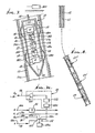
- a carrier such as elongated housing 10 is movable in a borehole indicated at 11, the hole being cased at 11 a.
- Means such as a cable to travel the carrier lengthwise in the hole is indicated at 12.
- a motor or other manipulatory drive means 1 3 is carried by and within the carrier, and its rotary output shaft 14 is shown as connected at 1 5 to an angular rate sensor means 16.
- the shaft may be extended at 14a , 14b and 14C for connection to first acceleration sensor means 17, second acceleration sensor means 18, and a resolver 19.
- the accelerometers 17 and 18 can together be considered as means for sensing tilt
- These devices have terminals 16a-19a connected Via suitable slip rings with circuitry indicated at 29 carried within the carrier (or at the well surface, if desired).
- Circuitry 29 typically may include a feed back arrangement as shown in Fig. 7a and incorporating a feed back amplifier 21, a switch 22 having arm 22a and contacts 22b and 22c, and a switch actuator 23a.
- the resolver 19 When the actuator closes arm 22 s i with contact 22c, the resolver 19 is connected in feed back relation with the drive motor 13 via leads 2 4 , 25 and 26, and amplifier 21, and the apparatus operates for example as described in U.S. Patent No.3,753,296 to determine the azimuthal direction of tilt of the borehole at a first location in the borehole. See for example first location indicated at 27 in Fig. 8.
- Other U.S. Patents describing such operation are 4,199,869, 4,192,077 and 4,197,654. During such operation, the motor 13 rotates the sensor 16 and the accelerometers either continuously, or incrementally.
- the angular rate sensor 16 may for example take the form of one or more of the following known devices, but is not limited to them:
- Each such device may be characterised as having a "sensitive" axis, which is the axis about which rotation occurs to produce an output which is a measure of rate-of- turn, or angular rate ⁇ . That value may have components ⁇ 1 , ⁇ 2 , and ⁇ 3 , in a three axis coordinate system.
- the sensitive axis may be generally normal to the axis 20 of instrument travel in the borehole, or it may be canted at angle a relative to axis 20 (see canted sensitive axis 16b in Fig. 7).
- the acceleration sensor means 17 may for example take the form of one or more of the following known devices; however, the term “acceleration sensor means” is not limited to such devices:
- acceleration sensors include the accelerometers disclosed in U.S. Patents Nos. 3,753,296 and 4,199,869, having the functions disclosed therein. Such sensors may be supported to be orthogonal or canted at some angle relative to the carrier axis. They may be stationary or carouseled, or may be otherwise manipulated, to enhance accuracy and/or gain an added axis or axes of sensitivity.
- the sensor 17 typically has two input axes of sensitivity. A canted axis of sensitivity is seen at 17b in Fig. 7. The axis of sensitivity is the axis along which acceleration measurement occurs.
- the second accelerometer 18 may be like accelerometer 17, excepting that its input axis 23 is typically orthogonal to the input axes of the sensor 16 and of the accelerometer 17.
- the output of the second accelerometer 18 is connected via lead 30 (in Fig. 7a, contact 22b, switch arm 22a , and servo amplifier 2 1 to the drive motor 13).
- the servo system causes the motor to rotate the shaft 14 until the input axis 23 of accelerometer is horizontal (assuming that the borehole has tilt as in Fig. 8).
- Amplifier 1 typically includes signal conditioning circuits 21a, feedback compensation circuits 21 b, and power amplifier 21 driving the motor M shown at 13.
- accelerometer 17 would register +0.707 g or 45°, and the angular rate sensor 16 would register no input resulting from the earth's rate of rotation. If, then, the apparatus is raised (or lowered) in the borehole, while input axis 23 of accelerometer 18 is maintained horizontal, the output from accelerometer 17 would remain constant, assuming the tilt of the borehole remains the same. If, however, the hole tilt changes direction (or its elevation axis changes direction) the accelerometer 17 senses such change, the amount of such change being recorded at circuitry 29, or at the surface.
- the sensor 16 senses the change, and the sensor output can be integrated as shown by integrator circuit 31 in Fig. 7a - (which may be incorporated in circuitry 29, or at the surface) to register the angles of azimuth change.
- the instrumentation can be travelled at high speed along the tilted borehole while recording such changes in tilt and azimuth, to a second position (see position 27" in Fig. 8). At that position, the instrumentation is again operated as at 27 - (mode No. 1) to accurately determine borehole tilt and azimuth -essentially a recalibration step.
- the apparatus can be travelled hundreds or thousands of feet, operating in mode No. 2 as described, and between calibration positions at which travel is arrested and the device is opearted in mode No. 1.
- the above modes of operation are typically useful in the tilted portion of a borehole; however, normally the main i.e. lower portion of the oil or gas well is tilted to some extent, and requires surveying. Further, this part of the hole is typically at relatively high temperature where it is desirable that the instrumentation be moved quickly to reduce exposure to heat the invention lending itself to these objectives.
- the instrumentation can revert to mode No: 1 operation, at selected positions, as for example at 100 or 200 feet intervals. In a near vertical hole, azimuth contributes very little to hole position computation, so that mode No. 1 positions can be spaced relatively far apart, and thus this portion of the hole can be mapped rapidly, as well.
- the required transmission paths for signals from the surface to the survey tool and from the survey tool to the surface can be provided by a variety of methods. Such methods include:
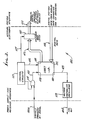
- analog voltages from the tool sensors and electronics are supplied on leads 112 to the analog data converter board 103 for multiplexed analog to digital conversion.
- analog output signals of the angular rate sensor G, 16 and the first acceleration sensor A 1 , 1 7 are supplied on leads 113 to the V/F (Voltage-to-Frequency) converter board, 104, for conversion to digital representations of the time integral of each signal.
- V/F Voltage-to-Frequency
- the integration and conversion of signals within board 104 are carried out by well-known means by using a voltage-to- frequency converter and a digital counter.
- the analog signals are mutiplexed in time sequence and converted to digital output by a well-known successive approximation register parallel output analog-to-digital converter.
- the outputs at boards 103 and 10 4 are available to the digital tool data bus, 110, and are placed on the bus and presented to the communications board, 102, at the times that that board wishes to receive such data.
- the communications board, 1 02 has a digital command bus, 111, by which it can transmit command data to tool modules such as diagnostic circuits, 105, the gimbal control servo, 106, the gyro loop board, 107, and the gyro wheel supply, 108. Any other module or board that is to receive command data can be connected to the same bus, 11.
- the communications board places the command data on the bus and addresses the proper module to read its command from the bus.
- the communications board can transmit any command that it has received from the surface equipment to the proper module. See equipment 300 in Fig. 7.
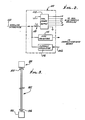
- Fig. 1 shows the exchange of data and commands between the communications board 102, and the surface computer, 155. Since, as previously stated, this particular embodiment of a two-way communications system uses time division multiplexing to control the bi- directional transmission the process begins with a command generated by the computer, 155. Such command may be for example a request for data from the survey tool or a mode of operation command. Such computer command is sent to the uphole computer interface, 150, in a standard RS232 format over leads 156. Within the uphole computer interface, 150, the serial command is converted to a frequency-shift-keyed (FSK) modulation and placed on lead 141 which is connected to the inner conductor of a two- conductor wireline.
- FSK frequency-shift-keyed
- the outer conductor, 144, of the wireline serves as a ground signal return path. Also connected to lead 14 1 through inductor L2, 150, and lead 157 is the uphole power supply 146 that provides a direct current power supply to the survey tool. Inductor L2 blocks the FSK signal from the power supply so it must flow through the wireline to the survey tool. At the survey tool end of the wireline the combined FSK signal arrives at inductor L1, 109, and lead 158. The direct current power supply output goes through L1, 109 and lead 11 O a to the power supply - FSK receiver for use in generating secondary power supply levels. The FSK signal is blocked by inductor L 1 , 109, and thus enters the power supply -FSK receiver, 100, via lead 158.
- the command signal is converted from FSK format to a serial digital signal at CMOS voltage levels for transmission of the command to the communications board, 102, by means of lead 10 1 a. Since it was assumed that the command was a request for data, the communications board gates in the commanded data from the digital data bus, 110, and combines it in the desired serial form, converts it to FSK, and returns it to the power supply -FSK receiver, 100 by lead 101 b.
- the FSK signal is used to modulate a current flowing in lead 158 which is connected to the wireline lead 141. Again, since inductor L1 and inductor L2, 109 and 150 respectively, block the FSK signal current, it must flow into the uphole computer interface, 150.
- the FSK signal is converted to a standard RS232 serial interface signal and transmitted to the computer, 155, by means of lead 156. Since the computer, 155, initiated the total sequence by requesting data, the computer has been waiting for data to return, and therefore recognizes the data stream as the response to its requests and uses the data as the computer program specifies. When the returning data includes mutiplexed A/D converter data, bits are included in the received message to identify which data is in each such word.
- Another function for the uphole computer, 155 is to control or adjust the uphole power supply, 146. This is done by the computer generating a power control signal which is sent to the uphole computer interface, 150, by the RS232 digital interface connection 156.
- the uphole computer interface, 150 in turn converts the power control signal to the form required by the uphole power supply, 146. This control signal is transmitted by lead.
- the uphole power supply, 146 uses this input signal on lead 147 to adjust the output voltage or current at lead 157 to the desired value.
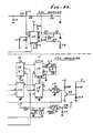
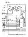
- Fig. 2 shows a block diagram of the power supply - FSK receiver, 100
- Fig. 5 shows a schematic of it
- Block 114 is the tool power supply and is of conventional design.
- the FSK receiver, 1 15 is a type XR-2211 FSK Demodulafor/Tone Decoder manufactured by EXAR, Inc., Sunnyvafe, California.
- the current modulator 116 is a single high-voltage transistor controlled by the signal input on line 101b.
- Fig. 3 shows a block diagram of the communications board, 102
- Fig. 6 is a schematic of it Control circuits, 117 generate the timing and control signals 118, 126, and 127 that control the communications process.
- the principal components other than the control circuitry are the UART, - (Universal asynchronous receiver transmitter) 119, the command word latch, 122, and the voltage controlled oscillator, 120.
- the UART of type 6402 manufactured by Harris Semiconductor Inc., Melbourne, Florida, can, under control of signals 126, accept a serial input at 128 from lead 125 to provide parallel outputs at 130 on bus 121 or accept parallel inputs at 131 on bus 110 and provide a serial output at 132 on lead 123.
- the gate, 118 is enabled so that the signal on lead 101a may be coupled to lead 125.
- control circuits When control circuits activate lead 127 to the command word latch, 122, the input data which has passed from serial input at 128 to parallel output at 130 and via bus 121 are coupled to the output digital command bus 111 and held there until a subsequent command is received-When digital data is to be transmitted to the surface, the control circuits, 117, initiate actions that cause successive parallel digital data words to be presented on the digital toot data bus, 110, which are in turn inputted to the UART at 131 and then outputted from the UART in serial form at 132 for transmission by lead 123 to the voltage controlled oscillator, 120.
- the voltage controlled oscillator may be an XR-2207 manufactured by EXAR, Inc., of Sunnyvale, California.
- the voltage controlled oscillator provides a frequency-shift-keyed, FSK, output at 101b which is modu- fated onto the wireline current by the power supply -FSK receiver, 100 and outputted on lead 158 as previously described to the wireline, 141, and the uphole computer interface, 150.
- FSK frequency-shift-keyed
- Fig. 4 is a schematic of the uphole computer interface 150. It contains an XR-2207 and an XR-2211 to perform the same functions as they do in the power supply -FSK receiver, 1 00, and the communications board, 102.
- Fig. 9 indicates the provision of alternate or auxiliary transmission paths, both up and down, between surface equipment 300, as described, and down-hole equipment 30 1 , as described. See for example equipments depicted in Fig. 1.
- the alternate transmission paths, indicated generally at 302 may take one of the following forms:
Landscapes
- Engineering & Computer Science (AREA)
- Physics & Mathematics (AREA)
- Mining & Mineral Resources (AREA)
- Remote Sensing (AREA)
- Life Sciences & Earth Sciences (AREA)
- Geology (AREA)
- Geophysics (AREA)
- Environmental & Geological Engineering (AREA)
- Fluid Mechanics (AREA)
- Electromagnetism (AREA)
- General Life Sciences & Earth Sciences (AREA)
- Geochemistry & Mineralogy (AREA)
- Geophysics And Detection Of Objects (AREA)
- Arrangements For Transmission Of Measured Signals (AREA)
- Reduction Or Emphasis Of Bandwidth Of Signals (AREA)
Applications Claiming Priority (2)
| Application Number | Priority Date | Filing Date | Title |
|---|---|---|---|
| US06/709,430 US4593559A (en) | 1985-03-07 | 1985-03-07 | Apparatus and method to communicate bidirectional information in a borehole |
| US709430 | 1985-03-07 |
Publications (3)
| Publication Number | Publication Date |
|---|---|
| EP0194792A2 true EP0194792A2 (fr) | 1986-09-17 |
| EP0194792A3 EP0194792A3 (en) | 1989-03-22 |
| EP0194792B1 EP0194792B1 (fr) | 1995-01-18 |
Family
ID=24849820
Family Applications (1)
| Application Number | Title | Priority Date | Filing Date |
|---|---|---|---|
| EP86301487A Expired - Lifetime EP0194792B1 (fr) | 1985-03-07 | 1986-03-03 | Procédé et dispositif pour la transmission de l'information dans les deux sens, dans un trou de forage |
Country Status (5)
| Country | Link |
|---|---|
| US (1) | US4593559A (fr) |
| EP (1) | EP0194792B1 (fr) |
| AT (1) | ATE117406T1 (fr) |
| CA (1) | CA1231134A (fr) |
| DE (1) | DE3650206D1 (fr) |
Cited By (1)
| Publication number | Priority date | Publication date | Assignee | Title |
|---|---|---|---|---|
| GB2394631A (en) * | 2002-10-23 | 2004-04-28 | Phoenix Petroleum Services | Signalling in a well |
Families Citing this family (22)
| Publication number | Priority date | Publication date | Assignee | Title |
|---|---|---|---|---|
| CN1022139C (zh) * | 1986-03-18 | 1993-09-15 | 切夫伦研究公司 | 利用非破坏性井下地震源获得地质结构信息的方法 |
| US4873522A (en) * | 1987-05-04 | 1989-10-10 | Eastman Christensen Company | Method for transmitting downhole data in a reduced time |
| US5264795A (en) * | 1990-06-18 | 1993-11-23 | The Charles Machine Works, Inc. | System transmitting and receiving digital and analog information for use in locating concealed conductors |
| US5343963A (en) * | 1990-07-09 | 1994-09-06 | Bouldin Brett W | Method and apparatus for providing controlled force transference to a wellbore tool |
| US5283768A (en) | 1991-06-14 | 1994-02-01 | Baker Hughes Incorporated | Borehole liquid acoustic wave transducer |
| US5493288A (en) * | 1991-06-28 | 1996-02-20 | Elf Aquitaine Production | System for multidirectional information transmission between at least two units of a drilling assembly |
| FR2679340B1 (fr) | 1991-06-28 | 1997-01-24 | Elf Aquitaine | Systeme de transmission pluridirectionnelle d'informations entre au moins deux unites d'un ensemble de forage. |
| US5679894A (en) * | 1993-05-12 | 1997-10-21 | Baker Hughes Incorporated | Apparatus and method for drilling boreholes |
| US5689248A (en) * | 1994-12-15 | 1997-11-18 | Gas Research Institute | Methods for reducing power consumption in remote sensing applications |
| DE19514120C2 (de) * | 1995-04-20 | 1999-02-11 | Siegfried Mueller | Bohrloch-Vermessungsgerät |
| US5606124A (en) * | 1996-05-20 | 1997-02-25 | Western Atlas International, Inc. | Apparatus and method for determining the gravitational orientation of a well logging instrument |
| EP1650401A3 (fr) * | 1998-12-02 | 2006-07-12 | Halli Burton Energy Services, Inc. | Procédé et appareil de diagraphie haute puissance |
| US8593266B2 (en) * | 1999-07-01 | 2013-11-26 | Oilfield Equipment Development Center Limited | Power line communication system |
| US9745799B2 (en) | 2001-08-19 | 2017-08-29 | Smart Drilling And Completion, Inc. | Mud motor assembly |
| US9051781B2 (en) | 2009-08-13 | 2015-06-09 | Smart Drilling And Completion, Inc. | Mud motor assembly |
| US8872670B2 (en) * | 2007-03-23 | 2014-10-28 | Schlumberger Technology Corporation | Compliance telemetry |
| US8065085B2 (en) | 2007-10-02 | 2011-11-22 | Gyrodata, Incorporated | System and method for measuring depth and velocity of instrumentation within a wellbore using a bendable tool |
| US8095317B2 (en) | 2008-10-22 | 2012-01-10 | Gyrodata, Incorporated | Downhole surveying utilizing multiple measurements |
| US8185312B2 (en) * | 2008-10-22 | 2012-05-22 | Gyrodata, Incorporated | Downhole surveying utilizing multiple measurements |
| US8065087B2 (en) | 2009-01-30 | 2011-11-22 | Gyrodata, Incorporated | Reducing error contributions to gyroscopic measurements from a wellbore survey system |
| US20150268368A1 (en) * | 2014-03-19 | 2015-09-24 | King Abdul Aziz City for Science and Technology (KACST) | Method and system for controlling geo-physical scanners |
| US11121675B2 (en) | 2019-12-24 | 2021-09-14 | International Business Machines Corporation | Remotely powered low power oscillator |
Family Cites Families (41)
| Publication number | Priority date | Publication date | Assignee | Title |
|---|---|---|---|---|
| US2309905A (en) * | 1941-04-29 | 1943-02-02 | Cooperative Dev Co | Device for surveying well bores |
| US2674049A (en) * | 1948-11-16 | 1954-04-06 | Union Oil Co | Apparatus for subsurface exploration |
| US2681567A (en) * | 1949-12-29 | 1954-06-22 | Stanolind Oil & Gas Co | System for obtaining and transmitting measurements in wells during drilling |
| US2635349A (en) * | 1950-12-02 | 1953-04-21 | Socony Vacuum Oil Co Inc | Well-surveying inclinometer |
| US2806295A (en) * | 1955-09-01 | 1957-09-17 | Exxon Research Engineering Co | Electrical borehole surveying device |
| US3037295A (en) * | 1958-04-21 | 1962-06-05 | Alvin R Allison | Process and means for determining hole direction in drilling |
| US3137077A (en) * | 1958-05-21 | 1964-06-16 | Adolph H Rosenthal | Drill-hole direction indicator |
| US3241363A (en) * | 1958-12-04 | 1966-03-22 | Honeywell Inc | Navigation instruments |
| US3229533A (en) * | 1960-11-21 | 1966-01-18 | Massachusetts Inst Technology | Gyroscopic apparatus and the art of employing same |
| US3242744A (en) * | 1962-02-26 | 1966-03-29 | Gen Precision Inc | Satellite vertical reference system |
| US3308670A (en) * | 1963-01-11 | 1967-03-14 | Aga Ab | Gyro platform arrangement |
| US3561129A (en) * | 1966-12-27 | 1971-02-09 | Us Army | North-seeking system |
| US3808697A (en) * | 1968-04-22 | 1974-05-07 | E Hall | Inclinometer |
| US3587175A (en) * | 1968-04-30 | 1971-06-28 | Texaco Inc | Method and apparatus for borehole directional logging |
| US3753296A (en) * | 1970-12-04 | 1973-08-21 | Applied Tech Ass | Well mapping apparatus and method |
| US3845569A (en) * | 1972-02-09 | 1974-11-05 | Selco Mining Corp Ltd | Bore hole logging device |
| DE2263338C3 (de) * | 1972-12-23 | 1979-10-25 | Teldix Gmbh, 6900 Heidelberg | Nordsuchender Kreisel |
| US3862499A (en) * | 1973-02-12 | 1975-01-28 | Scient Drilling Controls | Well surveying apparatus |
| CA999735A (en) * | 1973-08-08 | 1976-11-16 | Donald H. Van Steenwyk | Well mapping apparatus and method |
| GB1437125A (en) * | 1973-08-15 | 1976-05-26 | Applied Tech Ass | Well mapping apparatus and method |
| FR2241686A1 (en) * | 1973-08-20 | 1975-03-21 | Applied Tech Ass | Gyroscopic method of testing alignment of a borehole - wherein a boring pipe instrumentation case signals azimuth and inclination |
| US3959767A (en) * | 1974-08-21 | 1976-05-25 | General Electric Company | Data transmission system |
| US4071959A (en) * | 1975-03-25 | 1978-02-07 | King Russell Michael | Gyro-stabilized single-axis platform |
| US4065747A (en) * | 1975-11-28 | 1977-12-27 | Bunker Ramo Corporation | Acoustical underwater communication system for command control and data |
| FR2410724A1 (fr) * | 1977-12-02 | 1979-06-29 | Sagem | Perfectionnements apportes aux dispositifs pour l'exploration, en azimut et en inclinaison, d'une ligne de forage |
| FR2410725A1 (fr) * | 1977-12-02 | 1979-06-29 | Sagem | Perfectionnements apportes aux dispositifs pour la mesure de l'azimut et de l'inclinaison d'une ligne de forage |
| US4174577A (en) * | 1978-05-09 | 1979-11-20 | Harnessed Energies, Inc. | Borehole drift-direction probe |
| US4297790A (en) * | 1978-07-17 | 1981-11-03 | Applied Technologies Associates | Survey apparatus and method employing rate-of-turn and free gyroscopes |
| US4197654A (en) * | 1978-07-17 | 1980-04-15 | Applied Technologies Associates | Survey apparatus and method employing all latitude, all attitude gyrocompassing |
| US4192077A (en) * | 1978-07-17 | 1980-03-11 | Applied Technologies Associates | Survey apparatus and method employing rate-of-turn and free gyroscopes |
| US4245498A (en) * | 1978-12-06 | 1981-01-20 | The Singer Company | Well surveying instrument sensor |
| US4199869A (en) * | 1978-12-18 | 1980-04-29 | Applied Technologies Associates | Mapping apparatus employing two input axis gyroscopic means |
| US4461088A (en) * | 1979-05-07 | 1984-07-24 | Applied Technologies Associates | Survey apparatus and method employing canted tilt sensor |
| US4265028A (en) * | 1979-05-07 | 1981-05-05 | Applied Technologies Associates | Survey apparatus and method employing canted tilt sensor |
| US4302886A (en) * | 1979-10-29 | 1981-12-01 | Robert L. Fournet | Gyroscopic directional surveying instrument |
| US4464660A (en) * | 1979-12-06 | 1984-08-07 | S-Cubed | Multichannel remote transducer monitoring system |
| US4471533A (en) * | 1981-03-09 | 1984-09-18 | Applied Technologies Associates | Well mapping system and method with sensor output compensation |
| US4468863A (en) * | 1981-08-17 | 1984-09-04 | Applied Technologies Associates | High speed well surveying |
| US4472884A (en) * | 1982-01-11 | 1984-09-25 | Applied Technologies Associates | Borehole azimuth determination using magnetic field sensor |
| US4459760A (en) * | 1982-02-24 | 1984-07-17 | Applied Technologies Associates | Apparatus and method to communicate information in a borehole |
| US4433491A (en) * | 1982-02-24 | 1984-02-28 | Applied Technologies Associates | Azimuth determination for vector sensor tools |
-
1985
- 1985-03-07 US US06/709,430 patent/US4593559A/en not_active Expired - Lifetime
-
1986
- 1986-03-03 DE DE3650206T patent/DE3650206D1/de not_active Expired - Lifetime
- 1986-03-03 AT AT86301487T patent/ATE117406T1/de not_active IP Right Cessation
- 1986-03-03 EP EP86301487A patent/EP0194792B1/fr not_active Expired - Lifetime
- 1986-03-06 CA CA000503423A patent/CA1231134A/fr not_active Expired
Cited By (2)
| Publication number | Priority date | Publication date | Assignee | Title |
|---|---|---|---|---|
| GB2394631A (en) * | 2002-10-23 | 2004-04-28 | Phoenix Petroleum Services | Signalling in a well |
| GB2394631B (en) * | 2002-10-23 | 2006-04-12 | Phoenix Petroleum Services | Signalling method and apparatus |
Also Published As
| Publication number | Publication date |
|---|---|
| CA1231134A (fr) | 1988-01-05 |
| EP0194792A3 (en) | 1989-03-22 |
| DE3650206D1 (de) | 1995-03-02 |
| ATE117406T1 (de) | 1995-02-15 |
| US4593559A (en) | 1986-06-10 |
| EP0194792B1 (fr) | 1995-01-18 |
Similar Documents
| Publication | Publication Date | Title |
|---|---|---|
| EP0194792B1 (fr) | Procédé et dispositif pour la transmission de l'information dans les deux sens, dans un trou de forage | |
| CA1295678C (fr) | Methode et appareil de telemesure de la profondeur des puits de forage | |
| US6267185B1 (en) | Apparatus and method for communication with downhole equipment using drill string rotation and gyroscopic sensors | |
| US4611405A (en) | High speed well surveying | |
| US6816788B2 (en) | Inertially-stabilized magnetometer measuring apparatus for use in a borehole rotary environment | |
| US4909336A (en) | Drill steering in high magnetic interference areas | |
| CA2621496C (fr) | Procede et appareil pour transmettre des donnees de reponse de sonde et d'energie au travers d'un moteur a boue | |
| US4763258A (en) | Method and apparatus for trelemetry while drilling by changing drill string rotation angle or speed | |
| US4956823A (en) | Signal transmitters | |
| CN1965249B (zh) | 井下数据的地面实时处理 | |
| CA2584691C (fr) | Systeme d'accouplement par induction | |
| USRE35790E (en) | System for drilling deviated boreholes | |
| US4471533A (en) | Well mapping system and method with sensor output compensation | |
| US4197654A (en) | Survey apparatus and method employing all latitude, all attitude gyrocompassing | |
| US4468863A (en) | High speed well surveying | |
| GB2049197A (en) | System and method for monitoring drill string characteristics during drilling | |
| US20130099935A1 (en) | Light Based Communication Port For Use On Downhole Tools | |
| US4706388A (en) | Borehole initial alignment and change determination | |
| US4459760A (en) | Apparatus and method to communicate information in a borehole | |
| CN114658419A (zh) | 随钻测斜仪及随钻测斜方法 | |
| Wang et al. | Wireless data transmission options in rotary in-drilling alignment (R-IDA) setups for multilateral oil drilling applications | |
| JPH033535A (ja) | 高速ディジタル信号伝送装置 |
Legal Events
| Date | Code | Title | Description |
|---|---|---|---|
| PUAI | Public reference made under article 153(3) epc to a published international application that has entered the european phase |
Free format text: ORIGINAL CODE: 0009012 |
|
| AK | Designated contracting states |
Kind code of ref document: A2 Designated state(s): AT BE CH DE FR GB IT LI LU NL SE |
|
| PUAL | Search report despatched |
Free format text: ORIGINAL CODE: 0009013 |
|
| AK | Designated contracting states |
Kind code of ref document: A3 Designated state(s): AT BE CH DE FR GB IT LI LU NL SE |
|
| 17P | Request for examination filed |
Effective date: 19890826 |
|
| 17Q | First examination report despatched |
Effective date: 19920213 |
|
| GRAA | (expected) grant |
Free format text: ORIGINAL CODE: 0009210 |
|
| AK | Designated contracting states |
Kind code of ref document: B1 Designated state(s): AT BE CH DE FR GB IT LI LU NL SE |
|
| PG25 | Lapsed in a contracting state [announced via postgrant information from national office to epo] |
Ref country code: FR Effective date: 19950118 Ref country code: IT Free format text: LAPSE BECAUSE OF FAILURE TO SUBMIT A TRANSLATION OF THE DESCRIPTION OR TO PAY THE FEE WITHIN THE PRESCRIBED TIME-LIMIT;WARNING: LAPSES OF ITALIAN PATENTS WITH EFFECTIVE DATE BEFORE 2007 MAY HAVE OCCURRED AT ANY TIME BEFORE 2007. THE CORRECT EFFECTIVE DATE MAY BE DIFFERENT FROM THE ONE RECORDED. Effective date: 19950118 Ref country code: CH Effective date: 19950118 Ref country code: AT Effective date: 19950118 Ref country code: NL Effective date: 19950118 Ref country code: LI Effective date: 19950118 Ref country code: BE Effective date: 19950118 |
|
| REF | Corresponds to: |
Ref document number: 117406 Country of ref document: AT Date of ref document: 19950215 Kind code of ref document: T |
|
| REF | Corresponds to: |
Ref document number: 3650206 Country of ref document: DE Date of ref document: 19950302 |
|
| PG25 | Lapsed in a contracting state [announced via postgrant information from national office to epo] |
Ref country code: LU Free format text: LAPSE BECAUSE OF NON-PAYMENT OF DUE FEES Effective date: 19950331 |
|
| PG25 | Lapsed in a contracting state [announced via postgrant information from national office to epo] |
Ref country code: SE Effective date: 19950418 |
|
| PG25 | Lapsed in a contracting state [announced via postgrant information from national office to epo] |
Ref country code: DE Effective date: 19950419 |
|
| REG | Reference to a national code |
Ref country code: CH Ref legal event code: PL |
|
| EN | Fr: translation not filed | ||
| NLV1 | Nl: lapsed or annulled due to failure to fulfill the requirements of art. 29p and 29m of the patents act | ||
| PLBE | No opposition filed within time limit |
Free format text: ORIGINAL CODE: 0009261 |
|
| STAA | Information on the status of an ep patent application or granted ep patent |
Free format text: STATUS: NO OPPOSITION FILED WITHIN TIME LIMIT |
|
| 26N | No opposition filed | ||
| REG | Reference to a national code |
Ref country code: GB Ref legal event code: IF02 |
|
| PGFP | Annual fee paid to national office [announced via postgrant information from national office to epo] |
Ref country code: GB Payment date: 20050302 Year of fee payment: 20 |
|
| REG | Reference to a national code |
Ref country code: GB Ref legal event code: PE20 |
|
| PG25 | Lapsed in a contracting state [announced via postgrant information from national office to epo] |
Ref country code: GB Free format text: LAPSE BECAUSE OF EXPIRATION OF PROTECTION Effective date: 20060302 |