EP0194635B1 - Mécanique d'actionnement du boucleur et de la griffe de transport d'ouvrage sur machine à coudre portable - Google Patents
Mécanique d'actionnement du boucleur et de la griffe de transport d'ouvrage sur machine à coudre portable Download PDFInfo
- Publication number
- EP0194635B1 EP0194635B1 EP86103191A EP86103191A EP0194635B1 EP 0194635 B1 EP0194635 B1 EP 0194635B1 EP 86103191 A EP86103191 A EP 86103191A EP 86103191 A EP86103191 A EP 86103191A EP 0194635 B1 EP0194635 B1 EP 0194635B1
- Authority
- EP
- European Patent Office
- Prior art keywords
- hook
- cam
- claw
- casing
- mechanism according
- Prior art date
- Legal status (The legal status is an assumption and is not a legal conclusion. Google has not performed a legal analysis and makes no representation as to the accuracy of the status listed.)
- Expired
Links
- 230000007246 mechanism Effects 0.000 title claims description 34
- 238000009958 sewing Methods 0.000 title claims description 34
- 210000000078 claw Anatomy 0.000 title claims description 28
- 230000010355 oscillation Effects 0.000 claims description 12
- 230000015572 biosynthetic process Effects 0.000 claims description 3
- 230000002093 peripheral effect Effects 0.000 claims description 3
- 238000003780 insertion Methods 0.000 claims description 2
- 230000037431 insertion Effects 0.000 claims description 2
- 238000005461 lubrication Methods 0.000 description 3
- 230000003534 oscillatory effect Effects 0.000 description 2
- 235000002595 Solanum tuberosum Nutrition 0.000 description 1
- 244000061456 Solanum tuberosum Species 0.000 description 1
- 230000005540 biological transmission Effects 0.000 description 1
- 230000005484 gravity Effects 0.000 description 1
- 238000004806 packaging method and process Methods 0.000 description 1
- 238000005192 partition Methods 0.000 description 1
- 230000035515 penetration Effects 0.000 description 1
- 235000012015 potatoes Nutrition 0.000 description 1
Images


Classifications
-
- D—TEXTILES; PAPER
- D05—SEWING; EMBROIDERING; TUFTING
- D05B—SEWING
- D05B57/00—Loop takers, e.g. loopers
- D05B57/02—Loop takers, e.g. loopers for chain-stitch sewing machines, e.g. oscillating
Definitions
- This invention relates to a mechanism for actuating the hook and claw and for stitch setting in portable sewing machines.
- Portable sewing machines are employed to sew closed with chain stitch seams packages, sheets, and paper or canvas bags e.g. for packaging potatoes, granulated fodder, and so forth. Such machines are subjected, accordingly, to severe operating environments brought about, among other factors, by the nature of the materials handled, a dusty environment, the high sewing speeds sought, and so forth. These machines, moreover, are required to be reliable in operation and as light in weight as feasible.
- chain stitching is of the plain type, that is, the chain is formed by a sequence of individual loops which are intertwined progressively the one after another, the same being formed by means of a needle having an associated hook set to swing reciprovatingly around it over an angle of about 150-160°.
- a wider angle of rotary reciprocation of the hook is not presently achievable owing to constructional limitation inherent to prior designs.
- the hook is driven by the driveshaft through a cam, the latter having two spaced-apart detents cooperating with two detents, also spaced apart, which are provided rigidly with the hook carrier shaft.
- Prior machines further include a mechanism for actuating the feeder claw for the material being sewn.
- Such mechanisms require a large number of components, and accordingly, are bulky and heavy. This results in increased overall dimensions of the sewing machine, and attendant heavier weight thereof.
- Prior sewing machines are also provided with a mechanism made up of several parts for setting the sewing stitches to different lengths. This brings about, in turn, similar problems to the above. With prior machines, the large number of moving parts also pose wear problems and of attendant play formation. The net result is noisy operation and the need for frequent lubrication.
- the document US-A-1 657 989 discloses several embodiments of sewing mechanisms, whereby the loop formed by the needle is formed into two loops, a small loop and a large one.
- the shown mechanisms comprise a hooked finger provided with oscillating means, a strand deflecting member also provided with own rocking means and a usual rotary looper.
- the disclosed sewing mechanisms are made up of a large number of moving parts and are not fit either for actuating simultaneously the hooked finger and the claw or for setting the stitch length.
- the document DE-C-144 782 shows a sewing machine with a ring needle provided with a central hook-like projection.
- the rocking movement of the ring needle is derived from the main shaft of the sewing machine by means of a crank driving a rack which engages a sprocket mounted on the shaft of the ring needle.
- Means for setting the stitch length as well as means for operating the claw are neither suggested nor shown.
- This invention is based on the aim to provide mechanisms for actuating the hook and claw, and for setting the stitch length, which are simplified and afford an increased angle of rotary hook reciprocation, the proposed mechanism also affording double chain stitching ability and variability of the stitch length to suit the material being sewn or its contents, from the machine outside.
- the proposed mechanism is to have a reduced number of parts, and therefore, overall size and weight.
- the proposed mechanism should also afford high sewing speed ability, be highly reliable in operation even in heavy-duty applications, and make the usual lubrication practically unnecessary.
- a sewing machine comprising, for hook actuation, a cam profile cut with two oscillation detents, being associated with the machine driveshaft and carried in a box-type casing attached to the machine casing and cooperating with two counter-detents rigid with the hook shaft, supported obliquely on said box-type casing, the aim of this invention is achieved by that:
- the profile cut cam is a disk-like type of cam and the box-type casing has a cylindrical chamber accommodating said cam.
- the yarn guiding means consists of a peripheral shoulder one end of which starts from the junction to the hook base, which junction also forms a groove opening to a location close to the eye in the hook.
- the yarn feeding means for the double chain loop consists, according to the invention, of a guide tube on the exterior of the sewing machine casing which opens to a location close to the hook, some segments of said tube skirt, facing outwards from the sewing machine, being removed for better convenience in setting the yarn.
- the juts for a matching fit of the box-type casing into the sewing machine casing consist of an annulus.
- the bracket drive pin consists advantageously, according to the invention, of a pin received in a seating hole in the cam.
- the latter also has, on a front side thereof, a closure ring fitting with a slight clearance in the bottom wall of said box-type casing.
- the advantage is thus afforded of a single mechanism driving in common the hook and claw, which mechanism is advantageously formed of a small number of easily and quickly assembled parts, and enables the stitch length to be varied from its maximum value of about 11mm to its minimum value of about 3mm.
- the stitch length can be advantageously set from the machine exterior. That assembly, moreover, requires no complicated initial adjustment operations. Weight can be quite low and the overall size small. Operation is made advantageously highly reliable even at high sewing speeds. The latter may also be attained on account of the wider angle of rotary reciprocation now attainable with the proposed structure.
- Another advantage of the proposed mechanism is that a double chain stitch seam can be formed with a single hook.
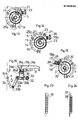
- Figure 1 a side elevation view of a sewing machine with the device of this invention depicted in phantom lines; in Figure 2 a front view of the sewing needle side of the same; in Figures 3 and 4, respectively a front view of the needle side of the part of the inventive mechanism, with the closure cover removed and at different rotational positions of the actuating cam; in Figures 5,6,7 and 8, various views of the hook of this invention, namely a view from below, a view from above, and two side elevation views from opposite sides thereof; in Figure 9 a vertical mid-sectional view taken through the actuating cam according to the invention in its cup-like casing supporting the hook.
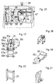
- FIGs 10,11 and 12 views of the inventive actuating cam, namely a front view of the front side opposing the bottom of the cup-like casing, a front view of the opposite side, and a view from above; in Figures 13 and 14, respectively a view of the actuating cam in its casing, and specifically in the two striking positions of the cam and hook foot marking the starts of two respective rotary reciprocations of the hook; in Figure 15 a view of the outer side of the cam casing with the claw drive parts removed for clarity; in Figure 16 a side elevation view of the actuating linkage for the claw and for changing the stitch length; in Figure 17, a view of the linkage taken in the direction of the arrow F in Figure 16; in Figures 18,19,20 and 21, perspective views of the block, connecting rod, linkage bracket, and stationary holder for the sane, respectively; in Figure 22 a detail view of the phase of penetration of the hook by the needle; and in Figures 23 and 24 an illustration of a plain chain stitch and double chain stitch seam section, respectively.
- Indicated at 1 is a sewing machine incorporating the mechanism of this invention.
- the same has a casing 2 accommodating the drive motor and power transmission of conventional design, no further illustrated herein.
- the output shaft of the drive system is indicated at 3.
- the same enters the chamber 4 housing the proposed mechanism.
- the latter comprises substantially a profile cut disk-like cam 5 keyed to the drive shaft 3 and being accommodated in a cup-like receiving seat 6 provided in the sacing 7 supporting said profile-cut cam 5.
- the casing 7 has a casing bottom 8 apertured in the middle at 9, and a flange 10 apertured as at 11 to let through screws 12 for fastening to the partition wall 13 of the chamber 4.
- Indicated at 14 is a ring collar of the casing 7 for geometrical engagement in a corresponding seat 15 in said wall 13.
- the casing 7 also has removed segments, as may be seen from the figures, for minimizing its overall size. Also provided on the casing 7 is a bored projection 16 (Figures 9,15) for supporting a pin 17 carrying on one end, by means of a dowel 18, the base 19 of the chip-like hook 20, and on the opposite end, a list foot 21 ( Figures 9,13,14). The conformations of the hook list 19a and the foot 21 may be seen from the various figures. Indicated at 22 and 23 are the counter-detents for the foot 21, which cooperate, to start a reciprocating oscillation, with a detent 24,25, respectively, in the form of corners cut to profile on the profile cut cam 5.
- the cam 5 is composed substantially of a first segment 26 and a second segment 27, the same having curvature radii R and r which differ from each other as explained hereinafter.
- the cam 5 has in the segment 26, on the side facing the bottom 8 of the casing 7, a profile cut depression 28, as may be seen from Figures 9,11, to allow the foot 21 to oscillate freely therein.
- a greatly reduced overall size is attained.
- a seat 29 for accommodating a drive pin 30 for the claw 31 arranged to drive the claw through a linkage comprising a connecting rod 32 accommodating the drive pin 30, a bracket 33 hingedly connected on one side at 33a to the connecting rod 32, and on the other side at 33b to a stationary support 34 attached at 34a to the casing 2, and a block 32 for setting the stitch length.
- the block 35 is hinged at the bottom at 35b to the connecting rod 32 and has at the top a head 35a to which there are hinged at 35c the arms 31b of the claw 31 being radiused together by a cross side 31c.
- the claw 31 has a middle head 31a the bottom side 31d whereof has a maximum oscillation distance a from the top side 35d of the head 35a, wherein an oscillation setting screw 47 having a head 47a is accommodated inside the threaded hole 35d.
- the maximum distance a is attained by loosening the screw 47 until its striking end reaches below the top side 35e of the block head 35a. With the screw 47 bottoming out, the cross side 31c will strike the head 35a and the block 35 and claw 31 form accordingly a rigid piece. In practice, the range of length variation of the stitches is from about 10-11mm to about 3mm.
- a hole 48 is provided in the bottom 4a of the chamber 4 and a hole 49 is provided through the connecting rod 32.
- Indicated at 50 is a closure cover hinged at 51.
- the hook list 19a has an open coil or chip-like configuration with an eye 36 close to its end for conducting a double chain stitch yarn 37 shown in dotted lines for claruty in Figure 24, whereas at 38 there is indicated the traditional plain chain stitch yarn led by the needle 39, with which the hook 20 is arranged to cooperate in a manner known per se.
- a yarn guide means 37 which comprises a small tube 40 on the casing 2 outside and has a yarn inlet end 41 and a bent end 42 extending inside the chamber 4 and being terminated close to the hook 20.
- the tube 40 has removed skirt portions along its length, no further shown in the drawing.
- a means of guiding the double chain stitch yarn 37 consisting of a peripheral shoulder 45 starting at one end from the junction of the hook coil to the base thereof, said shoulder extending then to form a groove 46 over the lower portion of the hook which opens close to the eye 36 thereof.
- the foot 21 On completion of this first 180° turn in one direction, the foot 21 will occupy the position shown in Figure 14, whereat the detent 25 of the cam 5 is striking the counter-detent 23 of said foot 21. As the rotation of the cam 5 is continued, there will first occur a 180° turn of the foot 21 in the opposite direction to the former, that rotation being brought about by the profile 25a. This is followed by a sliding engagement of an arcuate surface 21a of the foot 21 on the outside on the segment 27 of radius r, which for this reason is made smaller than the radius R of the segment 26, said segment 27 extending advantageously over about 225°. This engagement is then ensured mechanically, that is by positive mechanical sliding engagement, and during it there occurs a phase of hook stopping. Thus, we are back to the position of Figure 13.
- a sewing machine of the type indicated and incorporating the mechanism of this invention can have a lighter weight than 1.9kg.
- the proposed mechanism can have its parts modified in any way by a skilled person.
Landscapes
- Engineering & Computer Science (AREA)
- Textile Engineering (AREA)
- Sewing Machines And Sewing (AREA)
Claims (9)
- Mécanisme d'actionnement du crochet et de la griffe sur des machines à coudre portatives pour la couture au point de chaînette, comprenant une came de coupe curviligne ayant deux organes d'arrêt d'oscillation et étant associée avec l'arbre d'entraînement de la machine, et supporté sur un carter du type-boîte fixé au carter de machine à coudre et coopérant avec deux contre-organes d'arrêt formés sur un pied rigide avec l'arbre du crochet, supporté obliquement sur ledit carter du type-boîte, caractérisé en te que :i. la came de coupe curviligne (5) pour faire osciller le crochet (20) comporte également une goupille d'entraînement (30) pour actionner la griffe (31) par un élément de liaison interposé (32, 33, 34, 35), un élément (35) de ladite liaison (32, 33 34, 35) étant agencé pour avoir une longueur variable pour faire varier, la longueur de point ;ii. les deux contre-organes d'arrêt de crochet (22, 23) sont les extrémités d'un pied d'inclination (21) de la goupille support crochet (17) et les deux organes d'arrêt de came (18, 19) sont deux côtés transversaux de coupe curviligne de ladite came (5) entre lesquels côtés transversaux et au voisinage de quoi, ladite came (5) est logée (28) pour permettre la mise en place des dits organes d'arrêt (24, 25) sur la came et une oscillation non restreinte à l'intérieur de la came (5) dudit pied d'inclinaison (21) du crochet (20) alors que ledit crochet oscille ;iii. le crochet (20) a, sur sa partie de base (19), une configuration du genre et en bande bouclée (19a) ressemblent à un copeau ou bien à un serpentin sur environ un tour complet, sur l'extrémité libre de ladite bande de crochet (19a) étant formé un oeil (36) pour un fil en double chaîne formant couture (37) ;iv. un moyen de guidage (45, 46) est pourvu pour le fil en double chaîne de couture (37) sur le crochet (20) avec un moyen (40) de prise dudit fil formant couture en double chaîne (57) ;v. le carter du type-boîte (7) logant la camp comporte (5) un élément en saillie (14) pour l'ajustement dudit carter (7) par adaptation avec une forme en rapport dans le carter de machine à coudre (13).
- Mécanisme selon la revendication 1, dans lequel ledit moyen de liaison (32, 33, 34, 35) comprend une tige de liaison (32) articulée à une extrémité à la goupille d'entraînement de griffe (30), et à l'autre extrémité a un support (33), lequel, à son tour pivote avec son extrémité libre sur un support (34) fixé au carter de machine à coudre (2), en un point intermédiaire sur la tige de liaison (32) pivotant un bloc d'établissement de la longueur de point (35), ledit bloc ayant à son extrémité opposée une tête (35a) avec une vis de réglage de l'oscillation (47) s'engageant contre une tête juxtaposée (31a) de la griffe (31), et permettant à l'angle entre lesdites têtes pouvant osciller l'une par rapport à l'autre (35a, 31a) d'être modifié.
- Mécanisme selon la revendication 1, dans lequel la came de coupe curviligne (5) est du type d'une came. similaire à un disque, celle-ci ayant deux segments de came opposés (26, 27) avec des rayons différents (R, r) de courbure.
- Mécanisme selon la revendication 1, dans lequel le carter type-boîte (7) supportent la came (5) comporte un emplacement similaire à une coupe (6) formé à l'intérieur pour ladite came (5).
- Mécanisme selon le revendication 1, dans lequel le moyen de guidage du fil de couture en double chaîne (37) sur le crochet (20) comprend un épaulement périphérique (45) qui s'étend pour former une rainure (46) sur le côté formant fond de la bande de crochet (19a), ladite rainure (46) s'ouvrant sur une surface proche de l'oeil de crochet (36).
- Mécanisme selon la revendication 1, dans lequel le moyen de prise du fil de couture en double chaîne (37) comprend un tube de guidage (40) dont l'extrémité du côté de crochet (42) est terminée à une courte distance dudit crochet (20), et quelques segments de bordure externe dudit tube (40) sont retirés pour permettre une insertion manuelle plus aisée du fil (37).
- Mécanisme selon la revendication 1, dans lequel les saillies (14) pour l'adaptation du carter du type-boîte (7) par ajustement à une forme en rapport dans le carter de machine à coudre (2, 13) comprennent une couronne (14).
- Mécanisme selon la revendication 1, dans lequel la came de coupe curviligne (5) comporte, sur son côté faisant face à la goupille d'entraînement de griffe (30), une saillie similaire à une couronne (44) pour supporter un anneau de fermeture (43) apte à fermer, avec un léger espace, une ouverture (9) formée dans la paroi de fond (8) du carter du type-boîte (7) supportant la came (5).
- Mécanisme selon la revendication 1, caractérisé en ce que dans le fond de la chambre (4) logeant l'entraînement de griffe et crochet, comme dans la tige de liaison (32 ) sont prévus respectivement un trou débouchant (48, 49), aligné avec l'axe de la vis de détermination de longueur de point (47).
Applications Claiming Priority (2)
| Application Number | Priority Date | Filing Date | Title |
|---|---|---|---|
| IT1990485 | 1985-03-14 | ||
| IT19904/85A IT1184726B (it) | 1985-03-14 | 1985-03-14 | Meccanismo per l'azionamento del gancio e della griffa e per la regolazione dei punti in macchine da cucire portatili |
Publications (3)
| Publication Number | Publication Date |
|---|---|
| EP0194635A2 EP0194635A2 (fr) | 1986-09-17 |
| EP0194635A3 EP0194635A3 (en) | 1988-10-12 |
| EP0194635B1 true EP0194635B1 (fr) | 1991-08-07 |
Family
ID=11162214
Family Applications (1)
| Application Number | Title | Priority Date | Filing Date |
|---|---|---|---|
| EP86103191A Expired EP0194635B1 (fr) | 1985-03-14 | 1986-03-10 | Mécanique d'actionnement du boucleur et de la griffe de transport d'ouvrage sur machine à coudre portable |
Country Status (6)
| Country | Link |
|---|---|
| US (1) | US4693194A (fr) |
| EP (1) | EP0194635B1 (fr) |
| JP (1) | JPS61268288A (fr) |
| DE (1) | DE3680689D1 (fr) |
| ES (1) | ES8701258A1 (fr) |
| IT (1) | IT1184726B (fr) |
Families Citing this family (3)
| Publication number | Priority date | Publication date | Assignee | Title |
|---|---|---|---|---|
| DE3825094C1 (fr) * | 1988-07-23 | 1989-12-28 | Union Special Gmbh, 7000 Stuttgart, De | |
| US5233935A (en) * | 1992-05-15 | 1993-08-10 | Union Special Corporation | Looper throw-out safety catch device |
| CN107187663A (zh) * | 2017-06-17 | 2017-09-22 | 梁红雨 | 一种改进针架结构的手提电动封包机 |
Family Cites Families (8)
| Publication number | Priority date | Publication date | Assignee | Title |
|---|---|---|---|---|
| DE144782C (fr) * | ||||
| DE36166C (de) * | B. RUDOLPH in Berlin | Neuerung an WlLLCOX - Nähmaschinen zur Herstellung von Doppelkettenstich | ||
| US1657989A (en) * | 1922-01-17 | 1928-01-31 | baker | |
| US2538565A (en) * | 1939-08-12 | 1951-01-16 | American Mach & Foundry | Automatic stitch length adjusting mechanism |
| US2720853A (en) * | 1952-12-31 | 1955-10-18 | Trimless Inc | Stitch control for sewing machines |
| JPS5077043U (fr) * | 1973-11-16 | 1975-07-04 | ||
| US4311105A (en) * | 1978-01-30 | 1982-01-19 | Riccardo Buzzi | Sewing machine |
| IT8323703V0 (it) * | 1983-11-30 | 1983-11-30 | Rockwell Rimoldi Spa | Dispositivo di regolazione della traiettoria del crochet superiore in macchina per cucire a sopraggitto. |
-
1985
- 1985-03-14 IT IT19904/85A patent/IT1184726B/it active
-
1986
- 1986-03-03 US US06/835,267 patent/US4693194A/en not_active Expired - Fee Related
- 1986-03-10 EP EP86103191A patent/EP0194635B1/fr not_active Expired
- 1986-03-10 DE DE8686103191T patent/DE3680689D1/de not_active Expired - Fee Related
- 1986-03-13 JP JP61053859A patent/JPS61268288A/ja active Granted
- 1986-03-14 ES ES553057A patent/ES8701258A1/es not_active Expired
Also Published As
| Publication number | Publication date |
|---|---|
| EP0194635A2 (fr) | 1986-09-17 |
| ES8701258A1 (es) | 1986-12-01 |
| ES553057A0 (es) | 1986-12-01 |
| DE3680689D1 (de) | 1991-09-12 |
| IT1184726B (it) | 1987-10-28 |
| IT8519904A0 (it) | 1985-03-14 |
| EP0194635A3 (en) | 1988-10-12 |
| JPS61268288A (ja) | 1986-11-27 |
| US4693194A (en) | 1987-09-15 |
| JPH0423557B2 (fr) | 1992-04-22 |
Similar Documents
| Publication | Publication Date | Title |
|---|---|---|
| EP0194635B1 (fr) | Mécanique d'actionnement du boucleur et de la griffe de transport d'ouvrage sur machine à coudre portable | |
| US4669403A (en) | Drive for a tufting machine | |
| US4422396A (en) | Belt retainer guard for sewing machine | |
| US4422398A (en) | Top feed device for a sewing machine | |
| EP0385297B1 (fr) | Crochet oscillant pour une machine à coudre | |
| US4311105A (en) | Sewing machine | |
| US3285210A (en) | Looper drive for chain stitch sewing machines | |
| US4259914A (en) | Bobbin winding mechanism for a sewing machine | |
| JPH0259784U (fr) | ||
| US4438717A (en) | Needle protector for sewing machines | |
| US5802998A (en) | Automatic sewing machine for various articles, in particular leather articles | |
| US4178864A (en) | Looper control apparatus for sewing machines | |
| US3835716A (en) | Crank-driven reciprocating mechanisms | |
| US4771715A (en) | Zigzag sewing machine | |
| EP0288612B1 (fr) | Boucleur de machine à coudre | |
| US2990794A (en) | Bobbin thread case opener mechanism | |
| US4205616A (en) | Sewing machine for simultaneous hem stitching and blind stitching | |
| US4768452A (en) | Sewing machine | |
| US5934212A (en) | Two part sewing system for large work pieces | |
| US6269760B1 (en) | Wide needle swing oscillating hook system for sewing machines | |
| US5605062A (en) | Washing machine having an eccentric link for preventing a tangling of washing objects | |
| WO2003052192A1 (fr) | Machine a coudre a deux fils permettant de coudre une semelle a un dessus de chaussure | |
| US6047653A (en) | Sewing machine with a take-up lever moving up and down through one cycle per revolution of a rotary cylindrical hook base | |
| US3429275A (en) | Interlock sewing machines | |
| JP2960370B2 (ja) | 垂直全回転かま |
Legal Events
| Date | Code | Title | Description |
|---|---|---|---|
| PUAI | Public reference made under article 153(3) epc to a published international application that has entered the european phase |
Free format text: ORIGINAL CODE: 0009012 |
|
| AK | Designated contracting states |
Kind code of ref document: A2 Designated state(s): BE DE FR GB |
|
| PUAL | Search report despatched |
Free format text: ORIGINAL CODE: 0009013 |
|
| RHK1 | Main classification (correction) |
Ipc: D05B 1/10 |
|
| AK | Designated contracting states |
Kind code of ref document: A3 Designated state(s): BE DE FR GB |
|
| 17P | Request for examination filed |
Effective date: 19881216 |
|
| 17Q | First examination report despatched |
Effective date: 19900605 |
|
| GRAA | (expected) grant |
Free format text: ORIGINAL CODE: 0009210 |
|
| AK | Designated contracting states |
Kind code of ref document: B1 Designated state(s): BE DE FR GB |
|
| REF | Corresponds to: |
Ref document number: 3680689 Country of ref document: DE Date of ref document: 19910912 |
|
| ET | Fr: translation filed | ||
| PLBE | No opposition filed within time limit |
Free format text: ORIGINAL CODE: 0009261 |
|
| STAA | Information on the status of an ep patent application or granted ep patent |
Free format text: STATUS: NO OPPOSITION FILED WITHIN TIME LIMIT |
|
| 26N | No opposition filed | ||
| PGFP | Annual fee paid to national office [announced via postgrant information from national office to epo] |
Ref country code: GB Payment date: 19950220 Year of fee payment: 10 |
|
| PGFP | Annual fee paid to national office [announced via postgrant information from national office to epo] |
Ref country code: FR Payment date: 19950302 Year of fee payment: 10 |
|
| PGFP | Annual fee paid to national office [announced via postgrant information from national office to epo] |
Ref country code: BE Payment date: 19950309 Year of fee payment: 10 |
|
| PGFP | Annual fee paid to national office [announced via postgrant information from national office to epo] |
Ref country code: DE Payment date: 19950412 Year of fee payment: 10 |
|
| PG25 | Lapsed in a contracting state [announced via postgrant information from national office to epo] |
Ref country code: GB Effective date: 19960310 |
|
| PG25 | Lapsed in a contracting state [announced via postgrant information from national office to epo] |
Ref country code: BE Effective date: 19960331 |
|
| BERE | Be: lapsed |
Owner name: METALPLAST S.R.L. Effective date: 19960331 |
|
| GBPC | Gb: european patent ceased through non-payment of renewal fee |
Effective date: 19960310 |
|
| PG25 | Lapsed in a contracting state [announced via postgrant information from national office to epo] |
Ref country code: FR Effective date: 19961129 |
|
| PG25 | Lapsed in a contracting state [announced via postgrant information from national office to epo] |
Ref country code: DE Effective date: 19961203 |
|
| REG | Reference to a national code |
Ref country code: FR Ref legal event code: ST |