EP0194123A2 - Répartiteur modulaire à construction pour protecteur et module pour ce répartiteur - Google Patents
Répartiteur modulaire à construction pour protecteur et module pour ce répartiteur Download PDFInfo
- Publication number
- EP0194123A2 EP0194123A2 EP86301483A EP86301483A EP0194123A2 EP 0194123 A2 EP0194123 A2 EP 0194123A2 EP 86301483 A EP86301483 A EP 86301483A EP 86301483 A EP86301483 A EP 86301483A EP 0194123 A2 EP0194123 A2 EP 0194123A2
- Authority
- EP
- European Patent Office
- Prior art keywords
- module
- wires
- wire guide
- protecting
- wire
- Prior art date
- Legal status (The legal status is an assumption and is not a legal conclusion. Google has not performed a legal analysis and makes no representation as to the accuracy of the status listed.)
- Withdrawn
Links
Images


Classifications
-
- H—ELECTRICITY
- H04—ELECTRIC COMMUNICATION TECHNIQUE
- H04Q—SELECTING
- H04Q1/00—Details of selecting apparatus or arrangements
- H04Q1/02—Constructional details
- H04Q1/14—Distribution frames
-
- H—ELECTRICITY
- H04—ELECTRIC COMMUNICATION TECHNIQUE
- H04Q—SELECTING
- H04Q1/00—Details of selecting apparatus or arrangements
- H04Q1/02—Constructional details
- H04Q1/14—Distribution frames
- H04Q1/149—Wireguides in connector blocks
Definitions
- the present invention pertains generally to the field of telecommunications, and more particularly to the structure of distribution frames for distributing or cross-connecting incoming telecommunication lines, and overload protectors and test access features for such lines.
- Distribution frames are widely used in the telecommunications industry to interconnect equipment and distribution lines.
- typical distribution frames at a minimum consist of a panel or array containing a number of connection terminals, which may be wire wrapped post or insulation displacement terminals.
- the terminals are mounted on the front of the frames or panels on flat sheet metal members such that the lines entering or leaving the distribution frame may be connected directly to the terminals.
- the distribution line and the equipment lines are connected to the rear side of a panel, with distribution or cross-connection between the terminals effected from the front side.
- Distribution frames conventional in the prior art also include "protection" for operators and equipment This may be provided either by overvoltage protection circuits or overcurrent protection circuits which are wired between the equipment and distribution lines to protect against transfer from the distribution lines to equipment or equipment operators of environmental hazards such as lightning, the effects of which would otherwise be routed directly to electrical equipment interfaced with the lines on the distribution frame.
- Distribution frames of this type have certain limitations or disadvantages.
- One of these limitations is that typically it is often difficult to access the individual lines and test either in the distribution line direction or the equipment direction as desired from the front of the distribution frame panel.
- Another disadvantage is that many such systems must be wired from one side of the panel and then cross-connected from the other side, making access to the panel during the wiring process difficult and cumbersome.
- Third, over-voltage protector devices in the prior art are often expensive to fabricate, and subject to reliability problems.
- systems in the prior art typically have different connection terminals, one set of which are used for incoming and outgoing leads, and another set for cross-connect functions, which adds to expense and complexity.
- Fifth, many frames currently on the market are large panels, as opposed to a modular approach.
- the present invention provides a distribution frame made up of a number of modular elements, each of which has equipment leads, distribution leads, and cross-connect leads connected to front access terminals. This promotes both simplicity and cost effectiveness in wiring and testing.
- the invention includes a plurality of modules each of which fastens readily into an associated bracket structure.
- Each of these modules includes a plurality of individual circuit protector devices which insert from a front face thereof.
- a plurality of insulation displacement terminals Immediately adjacent the circuit protector structure are a plurality of insulation displacement terminals, each of which has an associated spring contact extension which makes contact to the overload protector when it is inserted.
- the contact between this terminal and the protector may be broken by a probe insertable into an aperture in the front face of the module which contacts the finger and flexes it away from the contact with the protector contact, at the same time allowing electrical contact with the individual conductor surface for test purposes.
- the individual modules have a wire guide structure which provides individual channels for each of the wires to allow front access to both the equipment and distribution line connections.
- the wire guide structure is further provided with a strain relief design forming a part thereof which facilitates reliability in the wiring.
- the protector includes a two-part cylindrical protector cover, which surrounds a printed circuit board, the ends of which extend outward from the protector cover.
- the printed circuit board has printed conductors on it which make connection to the insulation displacement connector contact extension.
- the board holds an overvoltage voltage or overcurrent protector, which is in turn encapsulated by the protector cover.
- the board extends out of opposite sides of the protector, one end contacting a ground clip, and the other end connecting associated contact extensions.
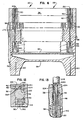
- Distribution frame 1 0 is made up of a U-shaped mounting bracket 12, with the legs of the U having individual pairs of mounting tabs, two pairs of which are labeled 14, 14, and 16, 16 respectively. Each pair of mounting tabs accepts an individual module, so that bracket 12 is configured to accept a total of 10 individual distribution frame modules.
- Distribution module 20 is a structure having a pair of individual mounting legs 22, 22, each of which has a slot or recess into which an associated mounting tab from bracket 12 may fit. As exemplified by the pair of mounting tabs 14, each mounting tab has a locking aperture. The locking aperture for one of tabs 14 is marked with reference numeral 24. As a part of the structure of module 20, legs 22 are fitted with a locking clip structure shown in more detail and described with reference to the cross-sectional view of FIGURE 8. /
- the distribution module 20 shown in FIGURE 1 would, under ordinary circumstances, be one of ten such modules which would be aligned across associated pairs of mounting tabs on bracket 12. Each such module 20 has a front face 28 on which connections to distribution lines and equipment are made. Front face 28 also 'accepts individual protector elements, as shown more particularly in FIGURE 2.
- distribution module 20 is shown in exploded perspective view.
- a representative overload protector element 32 is shown, and assembly lines indicate its insertion into front face 28.
- Each module 20, in the embodiment shown, is configured to accept ten aligned overload protector elements, as well as associated equipment and distribution lines serviced by such elements.
- front face 28 is a portion of a front cover 36 as shown.
- Front cover 36 is generally rectangular in shape and has two apertured ears 38 at opposite ends thereof to facilitate assembly of module 20.
- Front cover 36 is provided with a plurality of circularly cylindrical apertures 40. Each of these apertures is sized to accept an associated overload protector element 32.
- Immediately adjacent each aperture 40 are two pairs of terminal or connector apertures 42 and 44.
- each of these apertures provides access to a wire connector, both for purposes poses of wiring and for test.
- An individual one of said connectors is labeled with reference numeral 46, and is shown in FIGURE 2.
- This connector is often referred to a split cylinder insulation displacement connector, and contains an upper cylindrical portion 48, which forms the wire connecting portion or wire terminating end of the connector, and a contact portion, or end,comprising a pair of contact extensions or spring fingers 50 which extend longitudinally downward from portion 48.
- the upper cylindrical portion of connector 46 is preferably configured to accept more than one wire.
- An example of such structure is shown in an application assigned to the same assignee, filed in the name of Vasantrai Vachhani as inventor, and filed of even date herewith.
- Front cover 36 is fitted over module body 54.
- Module body 54 is structured to accept twenty pairs of connectors 46 across its length. It also mates with a body cover 58 to form a closed structure.
- Module body 54 has an assembly lug 60 at each end thereof.
- Body cover 58 likewise has an assembly lug 62 at each end thereof. These assembly lugs are captured within the aperture of each of ears 38 in assembly as front cover 36 fits over body cover 58 and module body 54.
- module body 5 4 The lower part of module body 5 4 is provided with an irregularly shaped recess which supports a ground strip 64 and a pair of mounting clips 66, 66.
- Mounting clips 66 may, in a certain class of preferred embodiments, be spot welded to metalic rectangular ground strip 64.
- Also attached to ground strip 64 are a plurality of metal grounding clips 68.
- Each of grounding clips 68 attaches to an associated grounding terminal on overload protector element 32 when it is inserted fully into module 20. Although two grounding clips are shown in FIGURE 2, in the configuration shown, there would be ten grounding clips spaced offset with respect to the center of ground strip 64 but longitudinally across the length of strip 64.
- FIGURE 2 Also shown in FIGURE 2 is a connecting wire guide 72 which, together with cover 36, body 54, and body cover 58 makes up the primary structure of module 20. It is contemplated that elements 36, 54, 58 and 72 will typically be molded from plastic or other suitable non-conductive material.
- Connecting wire guide 72 is basically a rectangular tangular structure with the exception of a strain relief configuration along the right edge of guide 72 as shown in FIGURE 2.
- the strain relief portion is generally designated 74 in FIGURE 2.
- wires from equipment to module body 54 initially pass through strain relief 74 at the right side of guide 72 then through a closed rectangular section passageway to any one of a number of longitudinally spaced wire exits, one of which is identified as wire exit 76.
- Wire guide 72 has two elongate assembly projections 78 along its bottom closed edge. Assembly projections 78 mate with assembly grooves 82 in assembly to lock wire guide structure 72 into assembly as part of the module.
- a side edge 83 fits flush against a lower surface 84 of cover 36 so that guide 72 is captured between an offset portion 86 of body cover 58 and front cover 36.
- front cover 36 has individual wire exit extensions 90 which register with wire exits 76 to provide a continuous passageway for wire up through front face 28 of cover 36.
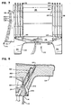
- wire guide 72 Further details of the structure of wire guide 72 are more particularly shown in the cut-away portion of FIGURE 5.
- individual wire passageways are shown in more detail.
- a representative of one of these passageways is labeled with reference numeral 94.
- Each passageway is typically capable, in the embodiment shown, of handling two connecting wires.
- Each passageway has a portion which runs horizontally as shown in FIGURE 5, and a radiussed bend portion which gently directs the wire upwardly as shown in FIGURE 5 to wire exit 76.
- Also shown in partial section in FIGURE 5 is a portion of front cover 36.
- Front cover 36 has a plurality of wire exit extensions 90 which guide the wires upwardly and out front face 28.
- strain relief elements 96 include a central arrow-shaped projection 100 for each passageway. On each side of the arrow-shaped projections 100, there is a corresponding bulb-shaped projection 104.
- the arrow-shaped outer end of projection 100 and the bulb-shaped outer end of projection 104 combine to create a narrow passageway which captures an individual wire placed through the narrow entry and into a recess, an example of which is labeled recess 106 in FIGURE 11.
- the strain relief side of wire guide 72 has a straight section followed by a segment which is angled outward. This is to facilitate easy connection and passage of wires through the wire guide-
- FIGURE 7 shows the reverse side of module body 54, and structure which provides the means for wiring the reverse side of module 20.
- a wire feed aperture 112 which may accept the wires from an incoming feed cable and route them to appropriate connection terminals.
- Aperture 112 feeds into a wire distribution recess 116 which is a regular trapezoid in shape and provides a space for individual wires to feed to each of a plurality of wire guide grooves, an example of which is marked 118 in the FIGURE.
- a wire distribution recess 116 which is a regular trapezoid in shape and provides a space for individual wires to feed to each of a plurality of wire guide grooves, an example of which is marked 118 in the FIGURE.
- 118 in the FIGURE 7, with ten protectors, there will be twenty individual wire guide grooves like 118.
- each of these grooves will be filled, in the example shown in FIGURE 7 only two wires are fed through aperture 112 across distribution recess 116 and into a pair of wire guide grooves upwardly for connection to connectors 46 for clarity in disclosure.
- the reverse side of body 54 as shown in FIGURE 7 may also be provided with narrowed sections 120 and 124 at opposite ends of wire guide grooves 1 18 to provide strain relief for the wire being connected on this side.
- FIGURE 4 shows additional details of the construction of front face 28 of cover 36. In particular, it shows circular apertures 40 into which individual overload protector elements 32 will fit
- FIGURE 4 of the drawings associated with each of apertures 4 0 are four individual contacts or connectors 46.
- One pair of contacts 46 accepts connecting wires from wire exit extensions 90, while the opposite pair accepts wires from wire guide grooves 118 previously discussed.
- wire to be connected would be guided through one or the other sets of guideways on one of the sides of module 20 through the strain relief sections, and across the tops of split cylinder connectors 46.
- a connection tool which can be used to perform a simultaneous cutoff, insulation displacement and connection function with respect to each of the wires captured by individual strain reliefs on front face 28, would then complete assembly.
- FIGURE 4 shows a pair of individual wires which have been connected, one set at each end of module 20 extending through one of wire exit extensions 90.
- FIGURE 4 Also shown in FIGURE 4 are the ends of four overload protector elements 32, two at each of the ends of front face 28.
- front face 28 includes a pair of cross-shaped apertures 130 on opposed sides of each of apertures 40.
- Cross shaped apertures 130 are also used for the purpose of what is typically referred to in the art as "break access" testing. This is a testing procedure in which there is a break in the circuit as part of the testing of equipment or condition of a distribution line.
- FIGURE 3 shows an exploded perspective view of overload protector element 32.
- a protector cover half 136 is formed to mate with a second protector cover half 140 to form a cover which is generally circularly cylindrical in shape.
- Cover halves 136 and 140 have recesses 144 and 146 which accept a printed circuit board element 150.
- a protector handle 154 At one end of protector cover half 136 is a protector handle 154 which allows ready insertion and removal of the protector during use.
- a truncated cone shaped end 156 At the opposite end of cover half 136.
- Printed circuit board 150 includes a conventional overload protection device, which in the embodiment shown is a gas over-voltage protection element of conventional type, which may be a gas discharge element 160.
- over-current protection could be incorporated on printed circuit board 150.
- the element 1 60 senses an over-voltage condition and shunts to ground if over-voltage occurs. If the over-voltage continues for an extended -time, element 160 heats up until an insulated wire shunt 164 becomes effective. At that point, the insulation on insulated wire shunt 16 4 melts and creates an alternate path to ground so that heating of element 160 is discontinued.
- the individual portions of elements 160 which need to be connected to contacts on printed circuit board 150 are typically soldered in place connections, and the printed circuit board contacts used provide an effective and inexpensive way of manufacturing a protector circuit with the desired contact configuration. The contact configuration can of course readily be changed merely by using an alternate printed circuit board.
- Printed circuit board 150 has a notch 166 which cooperates with contact fingers 50 so that by means of a slight upward shift of element 32, contact between fingers 50 and an associated contact, such as 1 68, is readily broken.
- FIGURE 6 illustrates the internal structure of module 20 when protector 32 is inserted therein.
- FIGURE 6 is a sectional view along the lines 6-6 of FIGURE 4 . In that view, a portion of printed circuit board 150 is shown in contact with clips 68. In the specific embodiment shown in FIGURE 3, this is identified as ground contact 172. Also shown in FIGURE 6 is the contact of the fingers 50 with appropriate contacts on printed circuit board 150. As shown in the FIGURE, fingers 50 are formed with rounded projections 174 thereon. Projections 174 make contact with appropriate contacts on board 150 when protector element 32 in inserted as shown in FIGURE 6.
- FIGURE 8 is a sectional view of a portion of module 20 to show the interaction between mounting tabs on bracket 12 and the mounting clips 66.
- a mounting tab 14 extends upward into a recess 180 in leg 22 of distribution module 20.
- each of the mounting tabs has a locking aperture 24 shown in the sectional view.
- a projection 184 mates with aperture 24 to firmly mount the module.
- Also shown in dotted in FIGURE 8 is an alternate form of mounting tab, wherein a single angular tab or bracket 188 extends upward into a mating angled recess or groove 1 92 in leg 22.
- mounting clips 66 are configured to accept either type of mounting without modification.
- FIGURE 9 is a sectional view of FIGURE 4 along the lines 9-9, and also shows a portion of a mounting tool working against a split cylinder insulation displacement connector to connect a wire on the left side thereof.
- an insulation displacement connector tool tip 200 is shown.
- the tool tip is configured with a central circularly cylindrical element which extends downward into the insulation displacement connector in a manner familiar to those of skill in the art of insulation displacement connectors.
- Tool tip 200 contains a second surrounding portion 206 which surrounds the element and forces the wire downward into the insulation displacement slot for connection. Surround 206 also cuts off excess wire from the opposite side of the connector.
- tool tip 200 contains a shoulder 210 which mates with the top edge of connector 46 to define the final vertical position of the wire being connected.
- FIGURES 12 and 13 illustrate a break access and test feature of the module structure.
- a test probe having a central cross shaped elongate projection 220 is shown.
- Cross shape projection 220 fits downward into mating aperture 130 in front face 28 to separate fingers 50 from contact with contacts on PC board 150 as shown by the arrows in FIGURE 13.
- probe. 218 contains a pair of spring loaded contacts 224, sometimes called "pogo" contacts which make resilient contact with the tops of connector elements 46. This permits the probe to break a circuit connection, and isolate either the distribution or equipment side from the front of the frame as desired.
Applications Claiming Priority (2)
| Application Number | Priority Date | Filing Date | Title |
|---|---|---|---|
| US707610 | 1985-03-04 | ||
| US06/707,610 US4729064A (en) | 1985-03-04 | 1985-03-04 | Modular interconnect block with protector structure |
Publications (2)
| Publication Number | Publication Date |
|---|---|
| EP0194123A2 true EP0194123A2 (fr) | 1986-09-10 |
| EP0194123A3 EP0194123A3 (fr) | 1989-04-05 |
Family
ID=24842392
Family Applications (1)
| Application Number | Title | Priority Date | Filing Date |
|---|---|---|---|
| EP86301483A Withdrawn EP0194123A3 (fr) | 1985-03-04 | 1986-03-03 | Répartiteur modulaire à construction pour protecteur et module pour ce répartiteur |
Country Status (5)
| Country | Link |
|---|---|
| US (1) | US4729064A (fr) |
| EP (1) | EP0194123A3 (fr) |
| JP (1) | JPS61280702A (fr) |
| AU (1) | AU587604B2 (fr) |
| CA (1) | CA1251849A (fr) |
Cited By (4)
| Publication number | Priority date | Publication date | Assignee | Title |
|---|---|---|---|---|
| EP0338187A2 (fr) * | 1988-04-20 | 1989-10-25 | KRONE Aktiengesellschaft | Fiche de protection pour boîters d'interuption ou de disjonction |
| FR2641154A1 (en) * | 1988-12-22 | 1990-06-29 | Saligny Yves | Telephone distribution board element such as cable head or terminal strip |
| EP0503704A2 (fr) * | 1991-03-05 | 1992-09-16 | Quante Ag | Profil de support pour blocs de connexion et/ou boîtiers de coupure pour les télécommunications |
| FR2700420A1 (fr) * | 1993-01-09 | 1994-07-13 | Krone Ag | Dispositif de fixation de réglettes à bornes utilisées dans la technique des télécommunications. |
Families Citing this family (32)
| Publication number | Priority date | Publication date | Assignee | Title |
|---|---|---|---|---|
| DE3629853A1 (de) * | 1986-09-02 | 1988-03-10 | Vorwerk Co Interholding | Stromversorgung fuer haushaltsgeraete |
| DE3710896A1 (de) * | 1987-04-01 | 1988-10-20 | Krone Ag | Verteilerleiste fuer fernmeldekabel, insbesondere hauseingangsverteilerleiste |
| US5035645A (en) * | 1988-01-15 | 1991-07-30 | The Siemon Company | Bracket for terminal block |
| US4912439A (en) * | 1989-01-27 | 1990-03-27 | General Electric Company | Molded case circuit breaker auxiliary switch unit |
| DE59105223D1 (de) * | 1990-06-11 | 1995-05-24 | Siemens Ag | Verteilereinrichtung. |
| US5160273A (en) * | 1991-06-24 | 1992-11-03 | Porta Systems Corp. | Connector block assembly |
| US5278720A (en) * | 1991-09-20 | 1994-01-11 | Atlantic Scientific Corp. | Printed circuit-mounted surge suppressor matched to characteristic impedance of high frequency transmission line |
| US5557250A (en) * | 1991-10-11 | 1996-09-17 | Raychem Corporation | Telecommunications terminal block |
| US6302723B1 (en) | 1991-10-11 | 2001-10-16 | Tyco Electronics Corporation | Telecommunications terminal block |
| FR2688370B1 (fr) * | 1992-03-03 | 1994-05-27 | Yves Saligny | Element de repartiteur telephonique, en particulier reglette. |
| US5423694A (en) * | 1993-04-12 | 1995-06-13 | Raychem Corporation | Telecommunications terminal block |
| FR2708794B1 (fr) * | 1993-08-04 | 1995-09-15 | Pouyet Int | Module d'interconnexion rapide de deux lignes téléphoniques monopaires. |
| US5356309A (en) * | 1994-01-26 | 1994-10-18 | Porta Systems Corp. | Connector block with releasable mounting |
| US5816854A (en) * | 1995-05-17 | 1998-10-06 | Lucent Technologies Inc. | Mounting bracket for connector block |
| US5696820A (en) * | 1995-09-13 | 1997-12-09 | Oneac Corporation | Telephone and data communications line conditioner system |
| US5779504A (en) * | 1995-09-29 | 1998-07-14 | Reltec Corporation | Modular terminal block assembly |
| US5724421A (en) * | 1995-11-16 | 1998-03-03 | Antec Corp. | Telephone network interface apparatus |
| US5742223A (en) * | 1995-12-07 | 1998-04-21 | Raychem Corporation | Laminar non-linear device with magnetically aligned particles |
| US5883953A (en) * | 1996-11-14 | 1999-03-16 | Oneac Corporation | Telephone and data communications line protection module and grounding spring clip |
| US5989062A (en) * | 1997-07-31 | 1999-11-23 | Lucent Technologies Inc. | Reversible receptacle for mounting connectors |
| US6005195A (en) * | 1998-01-12 | 1999-12-21 | Lucent Technologies Inc. | Cable retainer clip for electrical and/or optical equipment mounting structures |
| USD427151S (en) * | 1998-03-09 | 2000-06-27 | Schneider Automation, Inc. | Terminal module |
| USD425488S (en) * | 1998-03-09 | 2000-05-23 | Square D. Company | Terminal module |
| AUPP308498A0 (en) * | 1998-04-20 | 1998-05-14 | Krone Aktiengesellschaft | Electrical connector |
| US6111195A (en) * | 1999-01-13 | 2000-08-29 | Steelcase Inc. | Communications cabinet and mounting system |
| US6826280B1 (en) * | 1999-12-14 | 2004-11-30 | Adc Telecommunications, Inc. | Systems and methods for managing digital subscriber line (DSL) telecommunications connections |
| US6482311B1 (en) | 2000-08-01 | 2002-11-19 | Tda Research, Inc. | Methods for suppression of filamentous coke formation |
| US20060086530A1 (en) * | 2004-10-21 | 2006-04-27 | Robert Knabel | Wiring connector organizer |
| DE102008047375A1 (de) * | 2008-09-15 | 2010-04-15 | Cobi Net Fernmelde- Und Datennetzkomponenten Gmbh | Montagewanne |
| DE102013226069A1 (de) * | 2013-12-16 | 2015-06-18 | Tyco Electronics Amp Gmbh | Verteilerblock und Erdungsadapter |
| DE102013114315A1 (de) * | 2013-12-18 | 2015-06-18 | Phoenix Contact Gmbh & Co. Kg | Metallisches Schutzleiteranschlusselement und elektrische Reihenklemme |
| DE102016213286A1 (de) * | 2016-07-20 | 2018-01-25 | Harting Electric Gmbh & Co. Kg | Mehrteiliger Halterahmen, Konfektionier- und Bestückungsverfahren |
Citations (5)
| Publication number | Priority date | Publication date | Assignee | Title |
|---|---|---|---|---|
| DE2048104A1 (de) * | 1970-09-30 | 1972-04-13 | Siemens Ag | Verteilerleiste für elektrische Anlagen, insbesondere Fernsprechanlagen |
| FR2341974A1 (fr) * | 1976-02-18 | 1977-09-16 | Causse Raoul | Dispositif de protection de lignes basse tension, notamment pour reseau telephonique |
| EP0121223A1 (fr) * | 1983-03-29 | 1984-10-10 | Siemens Aktiengesellschaft | Barrette de répartition avec une multitude de bornes doubles pour le raccordement auxquelles le dénudage des conducteurs électriques n'est pas nécessaire |
| GB2140221A (en) * | 1983-03-30 | 1984-11-21 | Allied Corp | Electrical connectors |
| EP0204675A2 (fr) * | 1985-06-03 | 1986-12-10 | Adc Telecommunications, Inc. | Bâti de distribution modulaire comprenant des modules de protection adaptés pour être essayés par interruption du circuit |
Family Cites Families (21)
| Publication number | Priority date | Publication date | Assignee | Title |
|---|---|---|---|---|
| US3226669A (en) * | 1961-12-23 | 1965-12-28 | Ericsson Telefon Ab L M | Wire conductors in electrical connection fields |
| US3255330A (en) * | 1962-08-30 | 1966-06-07 | Cook Electric Co | Line protector |
| US3514743A (en) * | 1968-09-23 | 1970-05-26 | Deltrol Corp | Socket for plug-in electrical components with snap-in attachment to mounting panel |
| US3778750A (en) * | 1972-02-10 | 1973-12-11 | Panduit Corp | Wire termination and splicing system |
| US3760328A (en) * | 1972-04-19 | 1973-09-18 | Gte Automatic Electric Lab Inc | Telephone type electrical connectors |
| US3860318A (en) * | 1973-04-04 | 1975-01-14 | Amp Inc | Pre-loaded electrical connector |
| US3936133A (en) * | 1974-01-17 | 1976-02-03 | Cook Electric Company | Connector block for telephone equipment |
| US3964816A (en) * | 1974-08-22 | 1976-06-22 | Thomas & Betts Corporation | Electrical contact |
| CA1019041A (fr) * | 1974-09-20 | 1977-10-11 | Robert H. Knickerbocker | Bloc de connexion pre-cable a elements de traversee |
| US4057692A (en) * | 1976-10-27 | 1977-11-08 | Northern Telecom Limited | Protector apparatus for telecommunications lines |
| US4160574A (en) * | 1977-04-11 | 1979-07-10 | Bunker Ramo Corporation | Connector for flat wire cables having improved contacts and integral strain relief means |
| US4159158A (en) * | 1977-05-06 | 1979-06-26 | Amp Incorporated | Displation connector having improved terminal supporting means |
| AU518924B2 (en) * | 1977-11-12 | 1981-10-29 | Girling Limited | Valving controlling brake re-application pressure |
| US4163596A (en) * | 1978-01-27 | 1979-08-07 | Minnesota Mining And Manufacturing Company | Electrical connector |
| US4313147A (en) * | 1978-12-06 | 1982-01-26 | Kabushiki Kaisha Sankosah | Protective device for communication system |
| US4241970A (en) * | 1979-04-09 | 1980-12-30 | Amp Incorporated | Electrical connector having improved receptacle terminal |
| US4286836A (en) * | 1979-07-17 | 1981-09-01 | Teletype Corporation | Connector block with strain prevention |
| US4255009A (en) * | 1979-07-30 | 1981-03-10 | Amp Incorporated | Two row electrical connector |
| US4236778A (en) * | 1979-07-30 | 1980-12-02 | Amp Incorporated | Terminal block |
| US4283105A (en) * | 1979-12-07 | 1981-08-11 | Amp Incorporated | Terminal for cross connect apparatus |
| JPS58176392U (ja) * | 1982-05-20 | 1983-11-25 | 株式会社サンコ−シャ | アレスタ保持装置 |
-
1985
- 1985-03-04 US US06/707,610 patent/US4729064A/en not_active Expired - Fee Related
-
1986
- 1986-02-26 CA CA000502740A patent/CA1251849A/fr not_active Expired
- 1986-02-27 AU AU54133/86A patent/AU587604B2/en not_active Ceased
- 1986-03-03 EP EP86301483A patent/EP0194123A3/fr not_active Withdrawn
- 1986-03-04 JP JP61045472A patent/JPS61280702A/ja active Pending
Patent Citations (5)
| Publication number | Priority date | Publication date | Assignee | Title |
|---|---|---|---|---|
| DE2048104A1 (de) * | 1970-09-30 | 1972-04-13 | Siemens Ag | Verteilerleiste für elektrische Anlagen, insbesondere Fernsprechanlagen |
| FR2341974A1 (fr) * | 1976-02-18 | 1977-09-16 | Causse Raoul | Dispositif de protection de lignes basse tension, notamment pour reseau telephonique |
| EP0121223A1 (fr) * | 1983-03-29 | 1984-10-10 | Siemens Aktiengesellschaft | Barrette de répartition avec une multitude de bornes doubles pour le raccordement auxquelles le dénudage des conducteurs électriques n'est pas nécessaire |
| GB2140221A (en) * | 1983-03-30 | 1984-11-21 | Allied Corp | Electrical connectors |
| EP0204675A2 (fr) * | 1985-06-03 | 1986-12-10 | Adc Telecommunications, Inc. | Bâti de distribution modulaire comprenant des modules de protection adaptés pour être essayés par interruption du circuit |
Cited By (7)
| Publication number | Priority date | Publication date | Assignee | Title |
|---|---|---|---|---|
| EP0338187A2 (fr) * | 1988-04-20 | 1989-10-25 | KRONE Aktiengesellschaft | Fiche de protection pour boîters d'interuption ou de disjonction |
| EP0338187A3 (en) * | 1988-04-20 | 1990-09-19 | Krone Aktiengesellschaft | Safety plug for switching or disconnecting rails |
| FR2641154A1 (en) * | 1988-12-22 | 1990-06-29 | Saligny Yves | Telephone distribution board element such as cable head or terminal strip |
| EP0503704A2 (fr) * | 1991-03-05 | 1992-09-16 | Quante Ag | Profil de support pour blocs de connexion et/ou boîtiers de coupure pour les télécommunications |
| WO1992016076A1 (fr) * | 1991-03-05 | 1992-09-17 | Quante Ag | Profile porteur de barres de raccordement et/ou de separation utilise dans la techniques des telecommunications |
| EP0503704A3 (en) * | 1991-03-05 | 1993-09-29 | Quante Ag | Supporting rail profile for terminal blocks and/or for disconnection blocks for telecommunication |
| FR2700420A1 (fr) * | 1993-01-09 | 1994-07-13 | Krone Ag | Dispositif de fixation de réglettes à bornes utilisées dans la technique des télécommunications. |
Also Published As
| Publication number | Publication date |
|---|---|
| US4729064A (en) | 1988-03-01 |
| CA1251849A (fr) | 1989-03-28 |
| JPS61280702A (ja) | 1986-12-11 |
| AU587604B2 (en) | 1989-08-24 |
| EP0194123A3 (fr) | 1989-04-05 |
| AU5413386A (en) | 1986-09-11 |
Similar Documents
| Publication | Publication Date | Title |
|---|---|---|
| EP0194123A2 (fr) | Répartiteur modulaire à construction pour protecteur et module pour ce répartiteur | |
| EP0204675B1 (fr) | Bâti de distribution modulaire comprenant des modules de protection adaptés pour être essayés par interruption du circuit | |
| RU2133071C1 (ru) | Усовершенствованная система перекрестного соединения для телекоммуникационных систем | |
| US5647760A (en) | Insulation displacement contact including retention means | |
| KR100385805B1 (ko) | 커넥터모듈 | |
| EP0866519B1 (fr) | Contact électrique | |
| EP0645842A2 (fr) | Bloc de connexion avec protection | |
| AU708577B2 (en) | Distribution device for the telecommunication and data technique | |
| US5622516A (en) | Insulation displacement terminal with two-wire insertion capability | |
| CA2175949A1 (fr) | Support de montage pour bloc de connexion | |
| CA2175947A1 (fr) | Montage de protecteurs dans des blocs de connexion | |
| EP1483808B1 (fr) | Module terminal de telecommunication | |
| US7059864B2 (en) | Distribution device of a telecommunications system | |
| AU703800B2 (en) | A modular multiple terminal block for cable connections to a main distributing frame for telecommunication and data lines | |
| HU187559B (en) | Distribution lath with double connecting clamps enabling tha joining of several electrical leads without removing thier insulation | |
| US6345991B1 (en) | Printed wiring board for connecting to pins | |
| EP1455543B1 (fr) | Dispositif de modules de télécommunication ayant au moins une fiche de protection | |
| EP0667650B1 (fr) | Système de connexion modulaire | |
| US7253358B2 (en) | Earth device, plug-in breaker and distribution board | |
| US6065975A (en) | Connector switching mechanism | |
| AU691182B2 (en) | Loading coil device | |
| US20090053934A1 (en) | Termination block with functional module | |
| US6671372B1 (en) | Printed wiring board cable cover | |
| DE8521662U1 (de) | Anschlußleiste für Telekommunikationsanlagen | |
| HU187620B (en) | Cable distributor with several double contact clamps enabling the junction of electric lines without removing thier insulation |
Legal Events
| Date | Code | Title | Description |
|---|---|---|---|
| PUAI | Public reference made under article 153(3) epc to a published international application that has entered the european phase |
Free format text: ORIGINAL CODE: 0009012 |
|
| AK | Designated contracting states |
Kind code of ref document: A2 Designated state(s): AT BE CH DE FR GB IT LI LU NL SE |
|
| PUAL | Search report despatched |
Free format text: ORIGINAL CODE: 0009013 |
|
| AK | Designated contracting states |
Kind code of ref document: A3 Designated state(s): AT BE CH DE FR GB IT LI LU NL SE |
|
| 17P | Request for examination filed |
Effective date: 19890911 |
|
| 17Q | First examination report despatched |
Effective date: 19911016 |
|
| STAA | Information on the status of an ep patent application or granted ep patent |
Free format text: STATUS: THE APPLICATION IS DEEMED TO BE WITHDRAWN |
|
| 18D | Application deemed to be withdrawn |
Effective date: 19920228 |
|
| RIN1 | Information on inventor provided before grant (corrected) |
Inventor name: SINGER, LOREN A., JR. |