EP0194085A2 - Tone detector with pseudo phase locked loop - Google Patents
Tone detector with pseudo phase locked loop Download PDFInfo
- Publication number
- EP0194085A2 EP0194085A2 EP86301283A EP86301283A EP0194085A2 EP 0194085 A2 EP0194085 A2 EP 0194085A2 EP 86301283 A EP86301283 A EP 86301283A EP 86301283 A EP86301283 A EP 86301283A EP 0194085 A2 EP0194085 A2 EP 0194085A2
- Authority
- EP
- European Patent Office
- Prior art keywords
- signal
- frequency
- tone
- output
- divider
- Prior art date
- Legal status (The legal status is an assumption and is not a legal conclusion. Google has not performed a legal analysis and makes no representation as to the accuracy of the status listed.)
- Withdrawn
Links
Images


Classifications
-
- H—ELECTRICITY
- H03—ELECTRONIC CIRCUITRY
- H03J—TUNING RESONANT CIRCUITS; SELECTING RESONANT CIRCUITS
- H03J7/00—Automatic frequency control; Automatic scanning over a band of frequencies
- H03J7/18—Automatic scanning over a band of frequencies
- H03J7/20—Automatic scanning over a band of frequencies where the scanning is accomplished by varying the electrical characteristics of a non-mechanically adjustable element
-
- H—ELECTRICITY
- H04—ELECTRIC COMMUNICATION TECHNIQUE
- H04H—BROADCAST COMMUNICATION
- H04H20/00—Arrangements for broadcast or for distribution combined with broadcast
- H04H20/44—Arrangements characterised by circuits or components specially adapted for broadcast
- H04H20/46—Arrangements characterised by circuits or components specially adapted for broadcast specially adapted for broadcast systems covered by groups H04H20/53-H04H20/95
- H04H20/47—Arrangements characterised by circuits or components specially adapted for broadcast specially adapted for broadcast systems covered by groups H04H20/53-H04H20/95 specially adapted for stereophonic broadcast systems
- H04H20/49—Arrangements characterised by circuits or components specially adapted for broadcast specially adapted for broadcast systems covered by groups H04H20/53-H04H20/95 specially adapted for stereophonic broadcast systems for AM stereophonic broadcast systems
-
- G—PHYSICS
- G01—MEASURING; TESTING
- G01R—MEASURING ELECTRIC VARIABLES; MEASURING MAGNETIC VARIABLES
- G01R23/00—Arrangements for measuring frequencies; Arrangements for analysing frequency spectra
- G01R23/02—Arrangements for measuring frequency, e.g. pulse repetition rate; Arrangements for measuring period of current or voltage
- G01R23/15—Indicating that frequency of pulses is either above or below a predetermined value or within or outside a predetermined range of values, by making use of non-linear or digital elements (indicating that pulse width is above or below a certain limit)
-
- H—ELECTRICITY
- H03—ELECTRONIC CIRCUITRY
- H03D—DEMODULATION OR TRANSFERENCE OF MODULATION FROM ONE CARRIER TO ANOTHER
- H03D3/00—Demodulation of angle-, frequency- or phase- modulated oscillations
Definitions
- This invention relates to the field of tone detectors and, more particularly, to detectors for use in AM stereo broadcast reception.
- An object of the present invention is to provide a tone detector which is highly accurate and very reliable.
- a more particular object is to provide such a detector without requiring any high precision, high cost, or adjustable components.
- a pseudo phase locked loop is achieved by using a fixed oscillator frequency such as the IF frequency with a programmable divider to create two frequencies, slightly above and below the desired frequency, respectively.
- the divider output is multiplied by the signal containing the received tone and, after filtering, a DC signal is produced which indicates the direction of the error in the derived frequency.
- the error signal controls the choice of divisor numbers so that the average output of the divider is maintained at the desired frequency.
- a second divider output is phase shifted to be in quadrature with the first output and, when this signal is multiplied by the signal containing the desired tone and then integrated, the resultant signal indicates the absence or presence of the tone. If the integrated signal is at an appropriate level, it can be used to control any circuit which is dependent on the presence of the tone, such as the stereo presence indicator lamp of a AM stereo receiver.
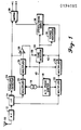
- Fig. 1 is a block diagram of an AM stereophonic broadcast receiver which utilizes the present invention.
- the basic receiver is the subject of a U.S. Patent No. 4,371,747, assigned to the assignee of the present invention. Its use here is exemplary only and no limitation on the invention should be inferred therefrom.
- This is a compatible amplitude modulated stereo signal in which L and R stand for the left and right stereophonic signals and A is the pilot tone or "stereo presence" signal.
- the received signal will be processed in an RF stage 12 and IF stage 14 as is known.
- a carrier source 16 together with a 90° phase shift network 18, provides two carrier signals in quadrature.
- the quadrature carriers are at 450 KHz, the IF frequency.
- the output of the IF stage 14 is coupled to two multiplier stages 20,22 where it is multiplied by the two quadrature carriers, providing outputs of (1+L+R) cos p and (L-R+A) cos ⁇ , respectively.
- the IF output is also coupled to an envelope detector 24 which has as its output the envelope Oodulation, (1+L+R).
- This sum signal is coupled to a matrix 26 and also to a comparator 28. In the comparator 28, the sum signal is compared with the output of a multiplier 30.
- the multiplier 30 has an input of (1+L+R) cos ⁇ from the multiplier 20 and a second input from the comparator 28 output.
- the output of the multiplier 30 is forced to be (1+L+R).
- the output of the multiplier 22 (L-R)cos ⁇ is coupled to a multiplier 32 which also receives the correction signal from the comparator 28.
- the output of the multiplier 32 thus becomes (L-R). This difference signal is also coupled to the matrix 26.
- an output 40 is taken from the carrier source 16 and coupled to a tone detector circuit 34 which will be described with respect to Fig. 2.
- the outputs of the tone detector are shown coupled to an indicator 36 and a switching circuit 38.
- the tone detector outputs may be used for whatever purposes are appropriate in a given application.
- the block diagram of Fig.. 2 shows a preferred embodiment of the tone detector 34 of Fig. 1.
- the signal input terminal 42 couples the difference signal to two multipliers 44,46, and a low pass filter 48.
- the difference signal in this embodiment is represented by (L-R+A), where L and R stand for left and right stereophonic signals and A stands for a low frequency tone (25Hz) which is present whenever stereo signals are being broadcast. It is the stereo or pilot tone A which is to be detected in this embodiment.
- the signal at terminal 42 would have some range and mixture of frequencies including a single frequency signal which it is necessary to detect reliably.
- the terminal 40 brings the 450 KHz signal into the tone detector 34 where it is coupled to a programmable divider circuit 50.
- the divider circuit has two available divisor numbers and, controlled by a signal from a comparator 52, "toggles" from one number to the other and back, so that the divider output is an average frequency; i.e., the tone frequency (A) to be detected.
- the divisors would be 18180 and 17820.
- the divider output would be either 24.75 or 25.25 Hz, averaging to 25 Hz over a period of time.
- the division process may be accomplished in two steps (or more, if desired).
- the divider output is coupled to a quadrature generator 54 which includes a 90° phase shifting network for providing two output signals in quadrature.
- the filter 48 output is coupled to a square wave generator 55. After squaring, the signal is coupled to an initializing circuit 56 which ensures that the divider 50 and quad generator 54 are operating in the proper phase relative to the signal A. (See Fig. 3.)
- the two outputs of the quad generator 54 are coupled to the multipliers 44, 46. Since the 25 Hz input to the multiplier 46 has been phase shifted 90° with respect to the phase of the A signal at terminal 42, the output of the multiplier will be forced to have the same value as the DC reference voltage of the circuit.
- the multiplier 46 output is coupled to the comparator 52, where it is compared to the ground or the DC reference voltage. If the signal coming into the multiplier 46 from the quad generator 54 is slightly higher than 25 Hz, there will be a DC voltage applied to the input of the comparator 52. This "error" voltage will cause the divider to switch to the larger divisor number, bringing the average frequency toward 25 Hz.
- the comparator output signal When the signal coming into the multiplier 46 is lower than 25 Hz, the comparator output signal will be of the opposite sign, again changing the divisor number in divider 50, this time to the smaller divisor. It can easily be seen that, with a simple R-C network (not shown) coupled to the output of the comparator 52, a DC voltage can be taken off for use in any circuit requiring a signal which is proportional to the distance off frequency.
- the signal provided at a terminal 60 is a fixed DC reference which, in this embodiment, will be about 20% of the expected maximum level of the signal A. This reference voltage is coupled to a comparator 62 for comparison with the output of the multiplier 44.
- the output of the comparator 62 is a DC signal representative of the presence or absence of the signal A in the broadcast signal received at the antenna 10, and this signal may be coupled to any circuits utilizing the tone detect information.
- the additional circuit including a timer 64 and an AND gate 66 may be included.
- the timer 64 is clocked by the 25 Hz signal from the quad generator 54, but any signal having a suitable frequency would suffice.
- One reset signal comes from a terminal 68 and is the.”mute" or "forced monaural" signal which is present in many stereo radios. In other applications, this signal could be any control signal which would represent a condition where the tone detect is not desired. Alternatively, the signal at terminal 68 could be omitted in some applications. When this signal is used and is zero, this input can reset the timer to a short timing period.
- Another reset signal for the timer comes from the comparator 62, so that when that signal indicates that either no stereo or stereo of insufficient level is present, the timer is reset to a long timing period. Since the output of the timer 64 is coupled to the AND gate 66, along with the pilot detect signal, the pilot detect signal is blocked or "defeated” until the timer runs out and is not reset.
- Fig. 3 shows exemplary schematic diagrams for some of the elements of the tone detector of Fig. 2.
- the low pass filter 48 may be omitted in some environments since the signal A may be "clean" enough to use without filtering.
- the signal from the terminal 42 or the filter/comparator output will be coupled to the square wave generator 55.
- the input of the generator 55 is essentially the signal A with some extraneous noise signals.
- the output of the generator 55 which is essentially a square wave at the frequency A, is coupled to one input of a NOR gate 70, whose output provides the "set” or "initializing” input to the quadrature generator 54.
- the "mute" input from the terminal 68 is coupled to a NOR gate 72 and to the reset input of a flip-flop 74, both forming parts of the initialization circuit 56.
- the signal on the terminal 68 must be high for initialization and the output of the flip-flop 74 will also be high.
- the F/F 74 output is coupled through a transistor Tl to the second input of the NOR gate 70.
- the output of the NOR 70, which provides the set inputs for the quadrature generator 54 is also coupled to the reset of the divider circuit 50.
- the quadrature generator 54 in the present embodiment consists of a dual D-type flip-flop such as the integrated circuit MC14013, manufactured by Motorola, Inc.
- the clock signal for the quadrature generator 54 has been derived from the divider circuit 50, and is 100 Hz for a 25 Hz signal A. Therefore, in this specific embodiment, the division process is shared by the divider 50 and the quadrature generator 54.
- the pair of output signals at the output terminals Ql,Q2 of the quadrature generator 54 are in quadrature with each other, with one of them in phase with the signal A at the terminal 42.
- the divider circuit 50 may be as shown or any appropriate combination of counters, gates, etc., which will provide the frequency divisions required for any particular environment. It will also be apparent that instead of just two divisor numbers, very close to the predetermined number, there could be a series of divisor numbers, progressively closer to the desired number, allowing the detector to more quickly approach the number.
Abstract
Description
- This invention relates to the field of tone detectors and, more particularly, to detectors for use in AM stereo broadcast reception.
- In many fields such as that of AM stereo, a single tone must be detected reliably and with accuracy. In the prior art, many systems have been devised for detecting a single frequency within a multi-frequency signal. Some of these have used a band-pass filter or a phase locked loop. In order to have accurate detection, the components of such filters must be very accurate, typically requiring + 1% tolerances. Such components are relatively expensive. When the cost of the adjustable elements of a PLL is included, the total may be out of the question except in the highest priced devices. What is most desirable is a low cost detector having greater accuracy than the prior art and requiring no adjustable elements.
- An object of the present invention is to provide a tone detector which is highly accurate and very reliable.
- A more particular object is to provide such a detector without requiring any high precision, high cost, or adjustable components.
- These and other objects which will become apparent are obtained in a detector according to the present invention wherein a pseudo phase locked loop is achieved by using a fixed oscillator frequency such as the IF frequency with a programmable divider to create two frequencies, slightly above and below the desired frequency, respectively. The divider output is multiplied by the signal containing the received tone and, after filtering, a DC signal is produced which indicates the direction of the error in the derived frequency. The error signal controls the choice of divisor numbers so that the average output of the divider is maintained at the desired frequency. A second divider output is phase shifted to be in quadrature with the first output and, when this signal is multiplied by the signal containing the desired tone and then integrated, the resultant signal indicates the absence or presence of the tone. If the integrated signal is at an appropriate level, it can be used to control any circuit which is dependent on the presence of the tone, such as the stereo presence indicator lamp of a AM stereo receiver.
-
- Fig. 1 is a block diagram of an AM stereo receiver including the present invention.
- Fig. 2 is a detailed block diagram of the tone detector of Fig. 1.
- Fig. 3 is a schematic diagram of a portion of the detector of Fig. 2.
- Fig. 1 is a block diagram of an AM stereophonic broadcast receiver which utilizes the present invention. The basic receiver is the subject of a U.S. Patent No. 4,371,747, assigned to the assignee of the present invention. Its use here is exemplary only and no limitation on the invention should be inferred therefrom.
- In this particular receiver, an
antenna 10 will receive a signal of the form (1+L+R) cos (wct + Ø), where p = tan-1 [(L-R+A)/(l+L+R)]. This is a compatible amplitude modulated stereo signal in which L and R stand for the left and right stereophonic signals and A is the pilot tone or "stereo presence" signal. The received signal will be processed in anRF stage 12 andIF stage 14 as is known. Acarrier source 16, together with a 90°phase shift network 18, provides two carrier signals in quadrature. The quadrature carriers are at 450 KHz, the IF frequency. In order to detect the stereo sum and difference signals, (L+R) and (L-R), the output of theIF stage 14 is coupled to twomultiplier stages envelope detector 24 which has as its output the envelope Oodulation, (1+L+R). This sum signal is coupled to amatrix 26 and also to acomparator 28. In thecomparator 28, the sum signal is compared with the output of amultiplier 30. Themultiplier 30 has an input of (1+L+R) cos ø from themultiplier 20 and a second input from thecomparator 28 output. Thus, by means of the comparator providing a correction signal of essentially (1/cos ø), the output of themultiplier 30 is forced to be (1+L+R). Similarly, the output of the multiplier 22 (L-R)cos ø is coupled to amultiplier 32 which also receives the correction signal from thecomparator 28. The output of themultiplier 32 thus becomes (L-R). This difference signal is also coupled to thematrix 26. - In accordance with the present invention, an
output 40 is taken from thecarrier source 16 and coupled to atone detector circuit 34 which will be described with respect to Fig. 2. Here the outputs of the tone detector are shown coupled to anindicator 36 and aswitching circuit 38. Obviously, the tone detector outputs may be used for whatever purposes are appropriate in a given application. - The block diagram of Fig.. 2 shows a preferred embodiment of the
tone detector 34 of Fig. 1. Thesignal input terminal 42 couples the difference signal to twomultipliers low pass filter 48. The difference signal in this embodiment is represented by (L-R+A), where L and R stand for left and right stereophonic signals and A stands for a low frequency tone (25Hz) which is present whenever stereo signals are being broadcast. It is the stereo or pilot tone A which is to be detected in this embodiment. In any application of this invention the signal atterminal 42 would have some range and mixture of frequencies including a single frequency signal which it is necessary to detect reliably. - The
terminal 40 brings the 450 KHz signal into thetone detector 34 where it is coupled to aprogrammable divider circuit 50. The divider circuit has two available divisor numbers and, controlled by a signal from acomparator 52, "toggles" from one number to the other and back, so that the divider output is an average frequency; i.e., the tone frequency (A) to be detected. In the present embodiment, with a source frequency of 450 KHz, the divisors would be 18180 and 17820. Thus the divider output would be either 24.75 or 25.25 Hz, averaging to 25 Hz over a period of time. As may be seen with respect to Fig. 3, the division process may be accomplished in two steps (or more, if desired). - The divider output is coupled to a
quadrature generator 54 which includes a 90° phase shifting network for providing two output signals in quadrature. Thefilter 48 output is coupled to asquare wave generator 55. After squaring, the signal is coupled to an initializingcircuit 56 which ensures that thedivider 50 andquad generator 54 are operating in the proper phase relative to the signal A. (See Fig. 3.) The two outputs of thequad generator 54 are coupled to themultipliers multiplier 46 has been phase shifted 90° with respect to the phase of the A signal atterminal 42, the output of the multiplier will be forced to have the same value as the DC reference voltage of the circuit. The basis for this is the trigonometric identity cos A sin A = (sin 2A)/2, with no output at the frequency A. It is assumed that the higher order terms have been filtered out in a filter 57. Themultiplier 46 output is coupled to thecomparator 52, where it is compared to the ground or the DC reference voltage. If the signal coming into themultiplier 46 from thequad generator 54 is slightly higher than 25 Hz, there will be a DC voltage applied to the input of thecomparator 52. This "error" voltage will cause the divider to switch to the larger divisor number, bringing the average frequency toward 25 Hz. When the signal coming into themultiplier 46 is lower than 25 Hz, the comparator output signal will be of the opposite sign, again changing the divisor number individer 50, this time to the smaller divisor. It can easily be seen that, with a simple R-C network (not shown) coupled to the output of thecomparator 52, a DC voltage can be taken off for use in any circuit requiring a signal which is proportional to the distance off frequency. - The "in phase" or 0° output of the
quad generator 54 has, of course, also been corrected to an average of 25 Hz. Since it is in phase with the input fromterminal 42, the output of themultiplier 44, after filtering in afilter 58, will be proportional to A, based on the identity cos A cos A = (1 + cos 2A)/2. It is to be understood that each of the capacitors referenced as 57,58 merely represents a filtering capability. The signal provided at a terminal 60 is a fixed DC reference which, in this embodiment, will be about 20% of the expected maximum level of the signal A. This reference voltage is coupled to acomparator 62 for comparison with the output of themultiplier 44. The output of thecomparator 62, then, is a DC signal representative of the presence or absence of the signal A in the broadcast signal received at theantenna 10, and this signal may be coupled to any circuits utilizing the tone detect information. - If an added measure of reliability is required, the additional circuit including a
timer 64 and an ANDgate 66 may be included. Thetimer 64 is clocked by the 25 Hz signal from thequad generator 54, but any signal having a suitable frequency would suffice. One reset signal comes from a terminal 68 and is the."mute" or "forced monaural" signal which is present in many stereo radios. In other applications, this signal could be any control signal which would represent a condition where the tone detect is not desired. Alternatively, the signal atterminal 68 could be omitted in some applications. When this signal is used and is zero, this input can reset the timer to a short timing period. Another reset signal for the timer comes from thecomparator 62, so that when that signal indicates that either no stereo or stereo of insufficient level is present, the timer is reset to a long timing period. Since the output of thetimer 64 is coupled to the ANDgate 66, along with the pilot detect signal, the pilot detect signal is blocked or "defeated" until the timer runs out and is not reset. - Fig. 3 shows exemplary schematic diagrams for some of the elements of the tone detector of Fig. 2. The
low pass filter 48 may be omitted in some environments since the signal A may be "clean" enough to use without filtering. Thus either the signal from the terminal 42 or the filter/comparator output will be coupled to thesquare wave generator 55. The input of thegenerator 55 is essentially the signal A with some extraneous noise signals. The output of thegenerator 55, which is essentially a square wave at the frequency A, is coupled to one input of a NORgate 70, whose output provides the "set" or "initializing" input to thequadrature generator 54. The "mute" input from the terminal 68 is coupled to a NORgate 72 and to the reset input of a flip-flop 74, both forming parts of theinitialization circuit 56. The signal on the terminal 68 must be high for initialization and the output of the flip-flop 74 will also be high. The F/F 74 output is coupled through a transistor Tl to the second input of the NORgate 70. The output of the NOR 70, which provides the set inputs for thequadrature generator 54 is also coupled to the reset of thedivider circuit 50. - The
quadrature generator 54 in the present embodiment consists of a dual D-type flip-flop such as the integrated circuit MC14013, manufactured by Motorola, Inc. The clock signal for thequadrature generator 54 has been derived from thedivider circuit 50, and is 100 Hz for a 25 Hz signal A. Therefore, in this specific embodiment, the division process is shared by thedivider 50 and thequadrature generator 54. The pair of output signals at the output terminals Ql,Q2 of thequadrature generator 54 are in quadrature with each other, with one of them in phase with the signal A at the terminal 42. Thedivider circuit 50 may be as shown or any appropriate combination of counters, gates, etc., which will provide the frequency divisions required for any particular environment. It will also be apparent that instead of just two divisor numbers, very close to the predetermined number, there could be a series of divisor numbers, progressively closer to the desired number, allowing the detector to more quickly approach the number. - Thus there has been shown and described a tone detector which not only does not require a phase locked loop and adjustable and/or expensive elements, but provides a much higher degree of accuracy and reliability than a PLL would provide. Other variations and modifications are possible, and it is intended to cover all such as fall within the scope of the appended claims.
Claims (2)
Applications Claiming Priority (2)
| Application Number | Priority Date | Filing Date | Title |
|---|---|---|---|
| US06/706,583 US4618981A (en) | 1985-02-28 | 1985-02-28 | Tone detector with pseudo phase locked loop |
| US706583 | 1985-02-28 |
Publications (2)
| Publication Number | Publication Date |
|---|---|
| EP0194085A2 true EP0194085A2 (en) | 1986-09-10 |
| EP0194085A3 EP0194085A3 (en) | 1987-12-16 |
Family
ID=24838222
Family Applications (1)
| Application Number | Title | Priority Date | Filing Date |
|---|---|---|---|
| EP86301283A Withdrawn EP0194085A3 (en) | 1985-02-28 | 1986-02-24 | Tone detector with pseudo phase locked loop |
Country Status (5)
| Country | Link |
|---|---|
| US (1) | US4618981A (en) |
| EP (1) | EP0194085A3 (en) |
| JP (1) | JPS61245750A (en) |
| KR (1) | KR940005382B1 (en) |
| CN (1) | CN1007196B (en) |
Families Citing this family (5)
| Publication number | Priority date | Publication date | Assignee | Title |
|---|---|---|---|---|
| US5001757A (en) * | 1989-12-22 | 1991-03-19 | Sprague Electric Company | FM stereo tone detector |
| US5915029A (en) * | 1998-04-23 | 1999-06-22 | Sony Corporation | Automated testing apparatus for electronic component |
| US8045717B2 (en) * | 2006-04-13 | 2011-10-25 | Media Tek Inc. | Stereo decoder and method for processing pilot signal |
| JP4245038B2 (en) * | 2006-11-02 | 2009-03-25 | ソニー株式会社 | PLL circuit, phase control method, and IC chip |
| US9444553B2 (en) * | 2012-07-05 | 2016-09-13 | Lumentum Operations Llc | Tunable coherent optical receiver and method |
Citations (4)
| Publication number | Priority date | Publication date | Assignee | Title |
|---|---|---|---|---|
| US4021653A (en) * | 1975-10-14 | 1977-05-03 | Motorola, Inc. | Digital programmable tone detector |
| US4159398A (en) * | 1977-09-27 | 1979-06-26 | Motorola, Inc. | Stereo presence signal for an AM stereo system |
| WO1981002822A1 (en) * | 1980-03-24 | 1981-10-01 | Motorola Inc | Am stereophonic decoder |
| EP0090134A1 (en) * | 1982-02-04 | 1983-10-05 | E-Systems Inc. | Programmable fine frequency detector |
Family Cites Families (6)
| Publication number | Priority date | Publication date | Assignee | Title |
|---|---|---|---|---|
| US4367444A (en) * | 1979-10-20 | 1983-01-04 | Racal Research Limited | Frequency discriminator and frequency modulator incorporating such discriminator |
| US4344038A (en) * | 1980-05-27 | 1982-08-10 | The Magnavox Company | Low frequency tone detector |
| US4405897A (en) * | 1981-03-02 | 1983-09-20 | Ael Microtel Ltd. | Frequency deviation testing and adjusting system for frequency modulated oscillators |
| US4377728A (en) * | 1981-03-04 | 1983-03-22 | Motorola Inc. | Phase locked loop with improved lock-in |
| US4368356A (en) * | 1981-03-20 | 1983-01-11 | Motorola Inc. | Pilot tone detector utilizing phase deviation signals |
| US4520503A (en) * | 1983-10-14 | 1985-05-28 | University Of New Mexico | Tone discrimination circuit |
-
1985
- 1985-02-28 US US06/706,583 patent/US4618981A/en not_active Expired - Lifetime
-
1986
- 1986-02-20 KR KR1019860001198A patent/KR940005382B1/en not_active IP Right Cessation
- 1986-02-21 CN CN86100930A patent/CN1007196B/en not_active Expired
- 1986-02-24 EP EP86301283A patent/EP0194085A3/en not_active Withdrawn
- 1986-02-28 JP JP61043867A patent/JPS61245750A/en active Granted
Patent Citations (4)
| Publication number | Priority date | Publication date | Assignee | Title |
|---|---|---|---|---|
| US4021653A (en) * | 1975-10-14 | 1977-05-03 | Motorola, Inc. | Digital programmable tone detector |
| US4159398A (en) * | 1977-09-27 | 1979-06-26 | Motorola, Inc. | Stereo presence signal for an AM stereo system |
| WO1981002822A1 (en) * | 1980-03-24 | 1981-10-01 | Motorola Inc | Am stereophonic decoder |
| EP0090134A1 (en) * | 1982-02-04 | 1983-10-05 | E-Systems Inc. | Programmable fine frequency detector |
Also Published As
| Publication number | Publication date |
|---|---|
| CN1007196B (en) | 1990-03-14 |
| KR860006872A (en) | 1986-09-15 |
| JPS61245750A (en) | 1986-11-01 |
| EP0194085A3 (en) | 1987-12-16 |
| US4618981A (en) | 1986-10-21 |
| CN86100930A (en) | 1986-09-17 |
| JPH0225302B2 (en) | 1990-06-01 |
| KR940005382B1 (en) | 1994-06-17 |
Similar Documents
| Publication | Publication Date | Title |
|---|---|---|
| US4675613A (en) | Noise compensated synchronous detector system | |
| US4254503A (en) | Radio receiver for tone modulated signals | |
| US4809012A (en) | Direction finding equipment | |
| US4495473A (en) | Digital phase shifting apparatus which compensates for change of frequency of an input signal to be phase shifted | |
| US4618981A (en) | Tone detector with pseudo phase locked loop | |
| US4488108A (en) | Phase detector error compensation apparatus | |
| EP0316878B1 (en) | Pll circuit for generating output signal synchronized with input signal by switching frequency dividing ratio | |
| GB1502254A (en) | Spread spectrum multiple access modulation system receivers | |
| US4371747A (en) | AM Stereophonic decoder | |
| US4414504A (en) | Fractional doppler counting | |
| EP1911151B1 (en) | Receiver for amplitude-modulated signals | |
| JPS61273005A (en) | Amplitude modulation system receiver | |
| KR880000649B1 (en) | Multiple tone pirot signal system | |
| US3327219A (en) | Detector circuits for directly strobing radio frequency signals | |
| US3121871A (en) | Direction finding system | |
| US4601060A (en) | Automatic digital fine tuning system | |
| GB1011513A (en) | Improvements in or relating to amplitude modulation measuring apparatus | |
| US3297964A (en) | Error avoidance system for sampling type afc circuit | |
| EP1064720B1 (en) | Demodulator circuits | |
| GB2172158A (en) | Phase corrector for zero-if radio receiver | |
| US3766482A (en) | Radiant energy receivers | |
| US3560979A (en) | Method and electrical circuit for processing airport runway localizer and glideslope information | |
| US4263558A (en) | Phase-selective amplifier | |
| JPS5931043Y2 (en) | Frequency divider circuit | |
| US5305010A (en) | Crystal oscillator synchronized digital very high frequency omni-range (VOR) instrumentation unit |
Legal Events
| Date | Code | Title | Description |
|---|---|---|---|
| PUAI | Public reference made under article 153(3) epc to a published international application that has entered the european phase |
Free format text: ORIGINAL CODE: 0009012 |
|
| AK | Designated contracting states |
Kind code of ref document: A2 Designated state(s): DE FR GB |
|
| PUAL | Search report despatched |
Free format text: ORIGINAL CODE: 0009013 |
|
| RHK1 | Main classification (correction) |
Ipc: H03D 3/00 |
|
| AK | Designated contracting states |
Kind code of ref document: A3 Designated state(s): DE FR GB |
|
| 17P | Request for examination filed |
Effective date: 19880610 |
|
| 17Q | First examination report despatched |
Effective date: 19880824 |
|
| STAA | Information on the status of an ep patent application or granted ep patent |
Free format text: STATUS: THE APPLICATION IS DEEMED TO BE WITHDRAWN |
|
| 18D | Application deemed to be withdrawn |
Effective date: 19890104 |
|
| RIN1 | Information on inventor provided before grant (corrected) |
Inventor name: ECKLUND, LAWRENCE MARVIN |