EP0193442A1 - Automatic camber control - Google Patents
Automatic camber control Download PDFInfo
- Publication number
- EP0193442A1 EP0193442A1 EP86400254A EP86400254A EP0193442A1 EP 0193442 A1 EP0193442 A1 EP 0193442A1 EP 86400254 A EP86400254 A EP 86400254A EP 86400254 A EP86400254 A EP 86400254A EP 0193442 A1 EP0193442 A1 EP 0193442A1
- Authority
- EP
- European Patent Office
- Prior art keywords
- aircraft
- attack
- angle
- altitude
- mach number
- Prior art date
- Legal status (The legal status is an assumption and is not a legal conclusion. Google has not performed a legal analysis and makes no representation as to the accuracy of the status listed.)
- Ceased
Links
Images

Classifications
-
- G—PHYSICS
- G05—CONTROLLING; REGULATING
- G05D—SYSTEMS FOR CONTROLLING OR REGULATING NON-ELECTRIC VARIABLES
- G05D1/00—Control of position, course or altitude of land, water, air, or space vehicles, e.g. automatic pilot
- G05D1/08—Control of attitude, i.e. control of roll, pitch, or yaw
- G05D1/0808—Control of attitude, i.e. control of roll, pitch, or yaw specially adapted for aircraft
- G05D1/0816—Control of attitude, i.e. control of roll, pitch, or yaw specially adapted for aircraft to ensure stability
- G05D1/0825—Control of attitude, i.e. control of roll, pitch, or yaw specially adapted for aircraft to ensure stability using mathematical models
-
- B—PERFORMING OPERATIONS; TRANSPORTING
- B64—AIRCRAFT; AVIATION; COSMONAUTICS
- B64C—AEROPLANES; HELICOPTERS
- B64C13/00—Control systems or transmitting systems for actuating flying-control surfaces, lift-increasing flaps, air brakes, or spoilers
-
- B—PERFORMING OPERATIONS; TRANSPORTING
- B64—AIRCRAFT; AVIATION; COSMONAUTICS
- B64C—AEROPLANES; HELICOPTERS
- B64C13/00—Control systems or transmitting systems for actuating flying-control surfaces, lift-increasing flaps, air brakes, or spoilers
- B64C13/02—Initiating means
- B64C13/16—Initiating means actuated automatically, e.g. responsive to gust detectors
Definitions
- the present invention relates to aircraft control systems and more particularly to a control system for automatically achieving minimum drag while trimming the pitching moment of an aircraft to zero.
- the optimization used with linear aerodynamic theory to define optinum aircraft geometry is shown to have application to the determination of optimum control surface deflections as a function of angle of attack necessary to provide a maximum lift-drag deflection for a multiplane aircraft configuration.
- This optimization technique is suggested as a research tool in designing an aircraft configuration so that an optimized performance characteristic, such as minimum trimmed drag, may be accomplished at a particular condition, such as a cruise condition.
- the present inventi. is an extension of the discussed prior art Lagrange optimization for a control system of a multiplane aircraft which enables automatic camber control. More specifically, the present invention is incorporated into an aircraft flight control computer so that optimum performance can be achieved during an entire range of actual flight conditions.
- the present invention constitutes an automatic camber control to position three control surfaces of an aircraft for optimum aerodynamic effeciency throughout the flight envelope.
- the three control surfaces include forwardly positioned canard, intermediately positioned flaperons and rearwardly located strake flaps.
- the present control system is utilized to deflect the flaperons to increase the wing camber during transonic maneuvering to reduce drag and improve performance.
- the control system is used to deflect the trailing edges of the flaperons to reduce camber and optimize performance.
- the automatic camber control concept of the present invention is employed to vary the wing camber and to position the canard and strake flaps for optimum performance throughout the flight envelope.
- the present automatic camber control system was designed to trim the multiplane aircraft X-29 although the concept is equally applicable to other multiplane configurations utilizing a number of control surfaces.
- the three control surfaces are controlled in an interrelated manner to allow the aircraft to operate on an optimum polar.
- the optimum three surface control positions are scheduled as a function of Mach number and altitude and are programmed into a flight control computer.
- the optimum three surface control schedule is developed by using a linear Lagrange Optimization Program that analyzes an aerodynamic sensitivity matrix to produce the optimum angle of attack, canard incidence, flaperon deflection and strake flap deflection to trim the pitching moment at a given lift coefficient and nominal center of gravity.
- the look-up table schedule in the flight control computer is programmed in the form of canard incidence as a function of angle of attack and strake flap deflection as a function of flaperon deflection at several Mach number and altitude conditions.
- the flight control computer trims the aircraft based on angle of attack, setting the proper canard incidence, then moving the flaperons and strake flaps in relation to each other to trim the residual pitching moment generated by the canard and angle of attack.
- Wind tunnel data on lift, pitching moment and drag coefficient characteristics are obtained for each of the control- combinations just discussed.
- This data is then input into a known Lagrange Optimization Program, as previously referenced, to determine a unique combination of canard, flaperon and strake flap positions that trim the pitching moment coefficient of an aircraft to zero while providing the minimum drag coefficient as a function of lift coefficient and/or angle of attack, Mach number and altitude.
- Lagrange Optimization Program utilized the Lagrange Optimization Program to optimize a single fixed set of design criteria found useful in the design of the aircraft configuration.
- a second step in the optimization program is to crossplot the data from FIGS. lA-lD as canard position versus angle of attack and position versus strake flap position at a constant lift coefficient for the desired Mach number and altitude envelope as shown in FIGS. 2 and 3, respectively. These figures are then tabulated and loaded into a look-up table in memory of the digital flight control computer of an aircraft.
- FIG. 4 illustrates the control surfaces in a multiplane aircraft configuration to which the present invention applies.
- An aircraft is generally indicated by reference 10 and the fuselage 12 of the aircraft mounts a canard 14 which is capable of undergoing variable deflection over the angular range i.
- the aircraft wing 16 includes a flaperon 18 capable of undergoing deflection over the angular range ⁇ f .
- a strake flap 20 is illustrated as having a deflection range ⁇ s .
- the forward portion of the aircraft- fuselage appends to a nose boom 22 which is colinear with the fuselage reference line or axis.
- the angle of attack a is defined between a given wind vector 24 and the fuselage reference line.
- the aircraft illustrated in FIG. 4 is also equipped with a conventional angle of attack vane sensor 26 which is conventionally mounted to the boom 22 for providing angle of attack (a) to the automatic camber control system 30 which will be discussed in greater detail in connection with F IG. 5.
- a conventional pitch rate gyro 28 is also connected to the automatic camber control system 30 to provide information to the system as to whether the aircraft is trimmed.
- FIGS. 4 and 5 the latter figure representing a block diagram of the automatic camber control system 30 which processes angle of attack, Mach number and altitude information so that the control surfaces 14, 18 and 20 can be adjusted to achieve minimum drag while the aircraft is trimmed to a zero pitching moment.
- FIG. 5 also indicates sensors for Mach number altitude and pitch rate. These would conventionally include a pitot static system, gyro and altimeter.
- the data from sensors 26 and 32 are provided to the input of a digital computer 34 where look-up tables, including the data of FIGS. 2 and 3 are stored, these data determining unqiue combination of canard, flaperon, and strake flap positions that have been determined by use of the Lagrange Optimization Program to trim the pitching moment to zero.
- Digital commands generated by computer 34 undergo conversion through a digital-analog converter 38 so that surface commands can be transmitted along wire 40 to the strake flap actuator 42, flaperon actuator 44, and canard actuator 46.
- the output - from these will respectively be sufficient control signals to generate the necessary angular deflections for the control surfaces, namely, ⁇ s , af, and i.
- the corresponding strake flaps 20, flaperons 18 and canard 14 are thereby adjusted to the zero trim condition.
- Pitch rate gyro 28 is sensitive to deviations from the trim condition during flight. A change from the trim condition causes the pitch rate gyro 28 to signal the digital computer 36 to initiate a new adjustment cycle for achieving a new optimum position. This is typically accomplished 40 times a second and therefore becomes a continual process during the entire flight of the aircraft.
Abstract
Wind tunnel data for a three control surface aircraft (10) is developed for lift, pitching moment, and drag coefficient characteristics. This data is then input into a Lagrange optimization program to determine a unique combination of canard, flap, (18) and strake flap (20) positions that trimmed the pitching moment coefficient to zero and provided the minimum drag coefficient as a function of lift coefficient and/or angle of attack, Mach number, and altitude. This program is exercised over the entire Mach number, altitude, and angle of attack range of the aircraft. The output from the Lagrange optimization program are then tabulated and loaded into the memory of a digital flight control computer (34) of an aircraft. As the aircraft flies, the angle of attack sensor (26), air data sensor and altimeter (32), determine the angle of attack, Mach number and altitude of the aircraft. By means of the computer, the position of the control surfaces are changed to the predetermined settings of the look-up table for minimum drag.
Description
- The present invention relates to aircraft control systems and more particularly to a control system for automatically achieving minimum drag while trimming the pitching moment of an aircraft to zero.
- Many advanced aircraft configurations of current interest feature multiple control surfaces that need to be carefully scheduled for optimum performance. By way of example, for a canard controlled fighter configuration, the task may be to schedule canard and wing leading edge and trailing edge flaps for minimum trimmed drag at a cruise condition. When the surfaces to be scheduled are few, the determination of the optimum setting of the surface is simple. However, often there are many surfaces to be considered which compounds the problem. During aircraft configuration development decisions must be made as to the control surface deflections to be tested and built into the configurations. The task of determining the optimum setting is therefore complex and time consuming. There is also the need for some synthesis in terms of the control deflections of the performance effect of so many variables.
- An optimization technique for assisting in the problems mentioned above encountered during aircraft design was published in a paper given at an AIAA Aircraft Systems and Technology Meeting, August 20-22, 1979, and entitled "Application of Lagrange Optimization to the Drag Polar Utilizing Experimental Data" by J. S. Kohn, an employee of the present assignee. The paper is numbered 79-1833.
- Theoptimization used with linear aerodynamic theory to define optinum aircraft geometry is shown to have application to the determination of optimum control surface deflections as a function of angle of attack necessary to provide a maximum lift-drag deflection for a multiplane aircraft configuration. This optimization technique is suggested as a research tool in designing an aircraft configuration so that an optimized performance characteristic, such as minimum trimmed drag, may be accomplished at a particular condition, such as a cruise condition.

- The present inventi. is an extension of the discussed prior art Lagrange optimization for a control system of a multiplane aircraft which enables automatic camber control. More specifically, the present invention is incorporated into an aircraft flight control computer so that optimum performance can be achieved during an entire range of actual flight conditions.
- The present invention constitutes an automatic camber control to position three control surfaces of an aircraft for optimum aerodynamic effeciency throughout the flight envelope. The three control surfaces include forwardly positioned canard, intermediately positioned flaperons and rearwardly located strake flaps. By way of example the present control system is utilized to deflect the flaperons to increase the wing camber during transonic maneuvering to reduce drag and improve performance. In addition during supersonic cruise, the control system is used to deflect the trailing edges of the flaperons to reduce camber and optimize performance. Thus, the automatic camber control concept of the present invention is employed to vary the wing camber and to position the canard and strake flaps for optimum performance throughout the flight envelope.
- The present automatic camber control system was designed to trim the multiplane aircraft X-29 although the concept is equally applicable to other multiplane configurations utilizing a number of control surfaces. By virtue of the present invention, the three control surfaces are controlled in an interrelated manner to allow the aircraft to operate on an optimum polar.
- The optimum three surface control positions are scheduled as a function of Mach number and altitude and are programmed into a flight control computer. The optimum three surface control schedule is developed by using a linear Lagrange Optimization Program that analyzes an aerodynamic sensitivity matrix to produce the optimum angle of attack, canard incidence, flaperon deflection and strake flap deflection to trim the pitching moment at a given lift coefficient and nominal center of gravity. The look-up table schedule in the flight control computer is programmed in the form of canard incidence as a function of angle of attack and strake flap deflection as a function of flaperon deflection at several Mach number and altitude conditions. The flight control computer trims the aircraft based on angle of attack, setting the proper canard incidence, then moving the flaperons and strake flaps in relation to each other to trim the residual pitching moment generated by the canard and angle of attack.
- The above-mentioned objects and advantages of the present invention will be more clearly understood when considered in conjunction with the accompanying drawings, in which:
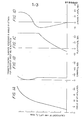
- FIGS. lA-lD are plots of trimmed control surface positions and angle of attack for a constant Mach number and altitude versus coefficient of lift;
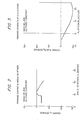
- FIG. 2 is a plot of trimmed canard versus angle of attack;
- FIG. 3 is a plot of trimmed strake flap versus flaperon deflections;
- FIG. 4 is a schematic view of an aircraft equipped with three control surfaces.
- In order to establish a control surface position matrix. for a look-up table as previously described, wind tunnel tests of the aircraft are conducted. At first the flaperon and strake flap positions are fixed while the canard position is varied at each Mach number over a range anticipated for aircraft operation. Next, the canard and strake flap positions are fixed while the flapero- position is varied over the range of Mach numbers. Finally, the canard and flaperon positions are fixed while the strake flap position is varied over the Mach number range.
- Wind tunnel data on lift, pitching moment and drag coefficient characteristics are obtained for each of the control- combinations just discussed. This data is then input into a known Lagrange Optimization Program, as previously referenced, to determine a unique combination of canard, flaperon and strake flap positions that trim the pitching moment coefficient of an aircraft to zero while providing the minimum drag coefficient as a function of lift coefficient and/or angle of attack, Mach number and altitude. A primary differentiation of the present invention over the prior art is that the prior art utilized the Lagrange Optimization Program to optimize a single fixed set of design criteria found useful in the design of the aircraft configuration. However, the present invention utilizes a series of Lagrange optimization calculations to form a control surface position matrix so that a resulting look-up table can be formulated enabling exercise of the look-up table over the entire Mach number, altitude, and angle of attack range of the aircraft. In other words the present invention improves upon the prior art by utilizing the Lagrange optimization calculations to vary three control surfaces with respect to one another during continually changing flight conditions for an aircraft. The output from the series of Lagrange optimization calculations may then be plotted in the form shown in FIGS. lA, lB, 1C and 1D. The coefficient of lift CL is conventionally defined by the weight divided by the product of free stream dynamic pressure and wing area. The angular quantities existing along the abscissas of the plots FIGS. lA-lD are pictorally illustrated in FIG. 4.
- A second step in the optimization program is to crossplot the data from FIGS. lA-lD as canard position versus angle of attack andposition versus strake flap position at a constant lift coefficient for the desired Mach number and altitude envelope as shown in FIGS. 2 and 3, respectively. These figures are then tabulated and loaded into a look-up table in memory of the digital flight control computer of an aircraft.

- FIG. 4 illustrates the control surfaces in a multiplane aircraft configuration to which the present invention applies. An aircraft is generally indicated by
reference 10 and thefuselage 12 of the aircraft mounts a canard 14 which is capable of undergoing variable deflection over the angular range i. The aircraft wing 16 includes aflaperon 18 capable of undergoing deflection over the angular range δf. Finally, in the three control surface example discussed herein, astrake flap 20 is illustrated as having a deflection range δs. The forward portion of the aircraft- fuselage appends to anose boom 22 which is colinear with the fuselage reference line or axis. The angle of attack a is defined between a given wind vector 24 and the fuselage reference line. The aircraft illustrated in FIG. 4 is also equipped with a conventional angle ofattack vane sensor 26 which is conventionally mounted to theboom 22 for providing angle of attack (a) to the automaticcamber control system 30 which will be discussed in greater detail in connection with FIG. 5. A conventionalpitch rate gyro 28 is also connected to the automaticcamber control system 30 to provide information to the system as to whether the aircraft is trimmed. - In order to better understand the structure and operation of the present invention, reference is now made to FIGS. 4 and 5, the latter figure representing a block diagram of the automatic
camber control system 30 which processes angle of attack, Mach number and altitude information so that thecontrol surfaces - As the
aircraft 10 flies, the angle ofattack sensor 26 generates instantaneous information relative to a. FIG. 5 also indicates sensors for Mach number altitude and pitch rate. These would conventionally include a pitot static system, gyro and altimeter. The data fromsensors 26 and 32 are provided to the input of adigital computer 34 where look-up tables, including the data of FIGS. 2 and 3 are stored, these data determining unqiue combination of canard, flaperon, and strake flap positions that have been determined by use of the Lagrange Optimization Program to trim the pitching moment to zero. Digital commands generated bycomputer 34 undergo conversion through a digital-analog converter 38 so that surface commands can be transmitted alongwire 40 to thestrake flap actuator 42,flaperon actuator 44, andcanard actuator 46. The output - from these will respectively be sufficient control signals to generate the necessary angular deflections for the control surfaces, namely, δs, af, and i. The corresponding strake flaps 20, flaperons 18 and canard 14 are thereby adjusted to the zero trim condition.Pitch rate gyro 28 is sensitive to deviations from the trim condition during flight. A change from the trim condition causes thepitch rate gyro 28 to signal thedigital computer 36 to initiate a new adjustment cycle for achieving a new optimum position. This is typically accomplished 40 times a second and therefore becomes a continual process during the entire flight of the aircraft. - It should be emphasized that, although the present invention is discussed in connection with an aircraft configuration having three
control surfaces - It should be understood that the invention is not limited to the exact details of construction shown and described herein for obvious modifications which occur to persons skilled in the art.
Claims (7)
1. In a multiplane aircraft having a plurality of control surfaces and provided with means for sensing angle of attack, Mach number, altitude and pitch rate, an automatic camber control system comprising:
computing means for storing a look-up table containing pre-established angular position data for each of the control surfaces which achieve minimum drag and zero pitching moment for sensed angle of attack, Mach number and altitude;
actuating means connected between the computing means and each of the control surfaces for deflecting each control surface to the pre-established angular positions after a non-zero pitching moment is found to exist for the aircraft; and
means connecting the pitch rate sensing means to the computing means for initiating a new cycle of control surface operation each time the sensing means signifies the occurrence of a non-zero pitching moment on the aircraft.
2. The system set forth in claim 1 wherein the control surfaces comprise: fore positioned canard, intermediately positioned flaperons, and aft positioned strake flaps.
3. The system set forth in claim 2 wherein the actuating means comprise individual means for adjusting the angular position of the canard, flaperons and strake flaps.
4. A method for continually updating the angular orientations of multiple control surfaces of an aircraft encountering changing flight conditions, the method comprising the steps of:
storing a look-up table containing pre-established angular position data for each of the control surfaces which achieves minimum drag and zero pitching moment for sensed angle of attack, Mach number and altitude;
deflecting each of the control surfaces to the pre-established angular positions after a non-zero pitching moment is found to exist at a determined Mach number, angle of attack, and altitude for the aircraft; and
initiating a new cycle of control surface operation each time a non-zero pitching moment exists for the aircraft.
5. The method set forth in claim 4 wherein the control surfaces comprise:
fore positioned canard, intermediately positioned flaperons, and aft positioned strake flaps.
6. The method set forth in claim 4 wherein the look-up table results from a number of steps comprising:
tabulating wind tunnel data at various Mach number conditions wherein each control surface is varied, as the remaining surfaces are held fixed;
the tabulation of data including lift, pitching moment and drag coefficients characteristics for each condition;
performing a Lagrange optimization for the derived tabulation of data for determining a unique combination of positions for the control surfaces that trim the pitching moment coefficient to zero and provide the minimum drag coefficient as a function of lift coefficient and angle of attack, Mach number, and altitude;
exercising the optimization over the entire Mach number, altitude and angle of attack range of the aircraft;
developing correlations from the optimization of angular position of a first control surface as a function of angle of attack and angular position relations of the remaining control surfaces at a constant lift coefficient for a desired Mach number and altitude envelope;.and
loading the resulting tabulations into a memory.
7. A method for continually updating the angular orientations of multiple control surfaces of an aircraft including canard, flaperons, and strake flap while the aircraft encounters changing flight conditions, the method comprising the steps of:
storing a look-up table containing pre-established angular position data for each of the control surfaces which achieves minimum drag and zero pitching moment for sensed angle of attack, Mach number and altitude;
deflecting each of the control surfaces to the pre-established angular positions after a non-zero pitching moment is found to exist at a determined Mach number, angle of attack, and altitude for the aircraft;
initiating a new cycle of control surface operation each time a non-zero pitching moment exists for the aircraft;
the look-up table resulting from a number of steps including
tabulating wind tunnel data at various Mach number conditions wherein each control surface is varied as the remaining surfaces are held fixed;
the tabulation of data including lift, pitching moment and drag coefficient characteristics for each condition;
performing a Lagrange optimization for the derived tabulation of data for determining a unique combination of positions for the control surfaces that trim the pitching moment coefficient to zero and provide the minimum drag coefficient as a function of lift coefficient and angle of attack, Mach number, and altitude;
exercising the optimization over the entire Mach number, altitude and angle of attack range of the aircraft;
developing correlations from the optimization of angular position of the canard versus angle of attack as well as flaperon position versus strake flap position at a constant lift coefficient for a desired Mach number and altitude envelope; and
loading the resulting tabulations into a memory.
Applications Claiming Priority (2)
| Application Number | Priority Date | Filing Date | Title |
|---|---|---|---|
| US702170 | 1985-02-15 | ||
| US06/702,170 US4723214A (en) | 1985-02-15 | 1985-02-15 | Automatic camber control |
Publications (1)
| Publication Number | Publication Date |
|---|---|
| EP0193442A1 true EP0193442A1 (en) | 1986-09-03 |
Family
ID=24820129
Family Applications (1)
| Application Number | Title | Priority Date | Filing Date |
|---|---|---|---|
| EP86400254A Ceased EP0193442A1 (en) | 1985-02-15 | 1986-02-06 | Automatic camber control |
Country Status (5)
| Country | Link |
|---|---|
| US (1) | US4723214A (en) |
| EP (1) | EP0193442A1 (en) |
| JP (1) | JPS61188299A (en) |
| CA (1) | CA1253835A (en) |
| IL (1) | IL76953A0 (en) |
Cited By (14)
| Publication number | Priority date | Publication date | Assignee | Title |
|---|---|---|---|---|
| EP0292558A1 (en) * | 1986-12-11 | 1988-11-30 | Grumman Aerospace Corporation | Flight control optimization system for multi-control surface aircraft |
| EP0680877A1 (en) * | 1994-05-03 | 1995-11-08 | AEROSPATIALE Société Nationale Industrielle | Transport aircraft with forward mounted stabilizer |
| EP0953504A1 (en) | 1998-04-29 | 1999-11-03 | Aerospatiale Societe Nationale Industrielle | Aircraft with reduced wing loads |
| EP1939703A1 (en) * | 2006-12-28 | 2008-07-02 | Saab Ab | System, computer program product and method for adjusting gain in a control system |
| EP2851286A1 (en) * | 2013-09-24 | 2015-03-25 | The Boeing Company | System and method for optimizing performance of an aircraft |
| US9180962B2 (en) | 2013-09-24 | 2015-11-10 | The Boeing Company | Leading edge variable camber system and method |
| US9193440B2 (en) | 2013-09-24 | 2015-11-24 | The Boeing Company | Variable camber flap system and method |
| EP2974955A3 (en) * | 2014-07-14 | 2016-03-16 | The Boeing Company | Closed loop control of aircraft control surfaces |
| US9296475B2 (en) | 2013-09-24 | 2016-03-29 | The Boeing Company | System and method for reducing the stopping distance of an aircraft |
| US9327827B2 (en) | 2013-09-24 | 2016-05-03 | The Boeing Company | Leading and trailing edge device deflections during descent of an aircraft |
| US9656741B2 (en) | 2013-09-24 | 2017-05-23 | The Boeing Company | Control interface for leading and trailing edge devices |
| US9771141B2 (en) | 2013-09-24 | 2017-09-26 | The Boeing Company | Leading edge system and method for approach noise reduction |
| RU2710955C1 (en) * | 2019-06-07 | 2020-01-14 | Юрий Константинович Краснов | Ignoring turbulence aircraft and aircraft attack angle change sensor |
| CN112357060A (en) * | 2020-10-29 | 2021-02-12 | 天津腾云智航科技有限公司 | Fixed wing unmanned aerial vehicle wing flap elevation convergence control method |
Families Citing this family (19)
| Publication number | Priority date | Publication date | Assignee | Title |
|---|---|---|---|---|
| JPS63180598A (en) * | 1987-01-22 | 1988-07-25 | 三菱重工業株式会社 | Take-off flare out control system |
| US5083279A (en) * | 1990-05-09 | 1992-01-21 | Honeywell, Inc. | Canard based high angle of attack air data sensor |
| FR2668750B1 (en) * | 1990-11-06 | 1993-01-22 | Aerospatiale | SYSTEM FOR INTEGRATED DEPTH AND PUSH CONTROL OF AN AIRCRAFT. |
| US5493497A (en) * | 1992-06-03 | 1996-02-20 | The Boeing Company | Multiaxis redundant fly-by-wire primary flight control system |
| US5486995A (en) * | 1994-03-17 | 1996-01-23 | Dow Benelux N.V. | System for real time optimization |
| DE69520097T2 (en) * | 1994-03-17 | 2001-07-19 | Dow Benelux | SYSTEM FOR REAL-TIME OPTIMIZATION AND PRESENTATION OF THE PROFIT |
| US5908176A (en) * | 1997-01-14 | 1999-06-01 | The United States Of America As Represented By The Administrator Of The National Aeronautics And Space Administration | In-flight adaptive performance optimization (APO) control using redundant control effectors of an aircraft |
| US5961068A (en) * | 1997-10-23 | 1999-10-05 | Northrop Grumman Corporation | Aerodynamic control effector |
| US6876991B1 (en) | 1999-11-08 | 2005-04-05 | Collaborative Decision Platforms, Llc. | System, method and computer program product for a collaborative decision platform |
| CA2474552C (en) * | 2002-01-30 | 2011-07-26 | Gulfstream Aerospace Corporation | Fuselage shaping and inclusion of spike on a supersonic aircraft for controlling and reducing sonic boom |
| US6698684B1 (en) | 2002-01-30 | 2004-03-02 | Gulfstream Aerospace Corporation | Supersonic aircraft with spike for controlling and reducing sonic boom |
| US7870334B2 (en) * | 2003-11-12 | 2011-01-11 | International Business Machines Corporation | Distributed task queues in a multiple-port storage system |
| US6935592B2 (en) * | 2003-08-29 | 2005-08-30 | Supersonic Aerospace International, Llc | Aircraft lift device for low sonic boom |
| CA3071172A1 (en) | 2005-12-15 | 2008-04-17 | Gulfstream Aerospace Corporation | Isentropic compression inlet for supersonic aircraft |
| US7946535B2 (en) * | 2006-10-18 | 2011-05-24 | Aerion Corporation | Highly efficient supersonic laminar flow wing |
| US8393158B2 (en) * | 2007-10-24 | 2013-03-12 | Gulfstream Aerospace Corporation | Low shock strength inlet |
| US20160200420A1 (en) * | 2014-09-25 | 2016-07-14 | Aurora Flight Sciences Corporation | System and method for unwanted force rejection and vehicle stability |
| CN109681380B (en) * | 2018-12-29 | 2022-09-30 | 新疆金风科技股份有限公司 | Method and device for adjusting the position of the minimum pitch angle |
| CN112270037B (en) * | 2020-10-15 | 2023-11-03 | 北京空天技术研究所 | Height modeling and flow control method for spoiler of embedded missile pod under high Mach number |
Citations (1)
| Publication number | Priority date | Publication date | Assignee | Title |
|---|---|---|---|---|
| FR2254481A1 (en) * | 1973-12-13 | 1975-07-11 | Messerschmitt Boelkow Blohm | Aircraft with canards and twin fin tailplane - has stable control afforded by canards anhedrally and fins dihedrally arranged |
Family Cites Families (11)
| Publication number | Priority date | Publication date | Assignee | Title |
|---|---|---|---|---|
| US2943823A (en) * | 1954-06-22 | 1960-07-05 | North American Aviation Inc | Trim correction system for high speed vehicles |
| US3215374A (en) * | 1962-01-10 | 1965-11-02 | North American Aviation Inc | Vehicle control system |
| US3240447A (en) * | 1962-01-10 | 1966-03-15 | North American Aviation Inc | Vehicle control system |
| US3399849A (en) * | 1966-05-11 | 1968-09-03 | Honeywell Inc | Lift and pitch control apparatus for aircraft |
| US3691356A (en) * | 1970-12-10 | 1972-09-12 | Sperry Rand Corp | Speed command and throttle control system for aircraft |
| US3734432A (en) * | 1971-03-25 | 1973-05-22 | G Low | Suppression of flutter |
| US4261537A (en) * | 1979-02-28 | 1981-04-14 | The United States Of America As Represented By The Administrator Of The National Aeronautics And Space Administration | Velocity vector control system augmented with direct lift control |
| US4382282A (en) * | 1980-09-08 | 1983-05-03 | Sperry Corporation | Trim control system for reduced drag |
| US4371936A (en) * | 1981-03-30 | 1983-02-01 | United Technologies Corporation | Attitude trimmed airspeed/attitude controls |
| US4562546A (en) * | 1983-01-13 | 1985-12-31 | Rockwell International Corporation | Stability augmentation system for a forward swept wing aircraft |
| US4569493A (en) * | 1983-03-14 | 1986-02-11 | Grumman Aerospace Corporation | Integrated multi-role variable sweep wing aircraft |
-
1985
- 1985-02-15 US US06/702,170 patent/US4723214A/en not_active Expired - Fee Related
- 1985-10-29 CA CA000494133A patent/CA1253835A/en not_active Expired
- 1985-11-05 IL IL76953A patent/IL76953A0/en unknown
-
1986
- 1986-02-03 JP JP61020314A patent/JPS61188299A/en active Pending
- 1986-02-06 EP EP86400254A patent/EP0193442A1/en not_active Ceased
Patent Citations (1)
| Publication number | Priority date | Publication date | Assignee | Title |
|---|---|---|---|---|
| FR2254481A1 (en) * | 1973-12-13 | 1975-07-11 | Messerschmitt Boelkow Blohm | Aircraft with canards and twin fin tailplane - has stable control afforded by canards anhedrally and fins dihedrally arranged |
Non-Patent Citations (1)
| Title |
|---|
| AVIATION WEEK & SPACE TECHNOLOGY, vol. 121, no. 10, 3rd September 1984, pages 51,52, New York, US; "Grumman begins X-29A taxi tests following aircraft rollout" * |
Cited By (22)
| Publication number | Priority date | Publication date | Assignee | Title |
|---|---|---|---|---|
| EP0292558A1 (en) * | 1986-12-11 | 1988-11-30 | Grumman Aerospace Corporation | Flight control optimization system for multi-control surface aircraft |
| EP0292558A4 (en) * | 1986-12-11 | 1989-09-19 | Grumman Aerospace Corp | Flight control optimization system for multi-control surface aircraft. |
| EP0680877A1 (en) * | 1994-05-03 | 1995-11-08 | AEROSPATIALE Société Nationale Industrielle | Transport aircraft with forward mounted stabilizer |
| FR2719548A1 (en) * | 1994-05-03 | 1995-11-10 | Aerospatiale | Transport plane with front empennage. |
| US5722615A (en) * | 1994-05-03 | 1998-03-03 | Aerospatiale Societe Nationale Indusrielle | Transport airplane with front empennage |
| EP0953504A1 (en) | 1998-04-29 | 1999-11-03 | Aerospatiale Societe Nationale Industrielle | Aircraft with reduced wing loads |
| FR2778163A1 (en) | 1998-04-29 | 1999-11-05 | Aerospatiale | AIRCRAFT WITH LOWER SAIL EFFORTS |
| US6064923A (en) * | 1998-04-29 | 2000-05-16 | Aerospatiale Societe Nationale Industrielle | Aircraft with reduced wing structure loading |
| EP1939703A1 (en) * | 2006-12-28 | 2008-07-02 | Saab Ab | System, computer program product and method for adjusting gain in a control system |
| US7987025B2 (en) | 2006-12-28 | 2011-07-26 | Saab Ab | Stores dependent angle of attack feedback |
| EP2851286A1 (en) * | 2013-09-24 | 2015-03-25 | The Boeing Company | System and method for optimizing performance of an aircraft |
| US9180962B2 (en) | 2013-09-24 | 2015-11-10 | The Boeing Company | Leading edge variable camber system and method |
| US9193440B2 (en) | 2013-09-24 | 2015-11-24 | The Boeing Company | Variable camber flap system and method |
| US9296475B2 (en) | 2013-09-24 | 2016-03-29 | The Boeing Company | System and method for reducing the stopping distance of an aircraft |
| US9327827B2 (en) | 2013-09-24 | 2016-05-03 | The Boeing Company | Leading and trailing edge device deflections during descent of an aircraft |
| US9359065B2 (en) | 2013-09-24 | 2016-06-07 | The Boeing Company | System and method for optimizing performance of an aircraft |
| US9656741B2 (en) | 2013-09-24 | 2017-05-23 | The Boeing Company | Control interface for leading and trailing edge devices |
| US9771141B2 (en) | 2013-09-24 | 2017-09-26 | The Boeing Company | Leading edge system and method for approach noise reduction |
| EP2974955A3 (en) * | 2014-07-14 | 2016-03-16 | The Boeing Company | Closed loop control of aircraft control surfaces |
| US9821903B2 (en) | 2014-07-14 | 2017-11-21 | The Boeing Company | Closed loop control of aircraft control surfaces |
| RU2710955C1 (en) * | 2019-06-07 | 2020-01-14 | Юрий Константинович Краснов | Ignoring turbulence aircraft and aircraft attack angle change sensor |
| CN112357060A (en) * | 2020-10-29 | 2021-02-12 | 天津腾云智航科技有限公司 | Fixed wing unmanned aerial vehicle wing flap elevation convergence control method |
Also Published As
| Publication number | Publication date |
|---|---|
| CA1253835A (en) | 1989-05-09 |
| IL76953A0 (en) | 1986-04-29 |
| JPS61188299A (en) | 1986-08-21 |
| US4723214A (en) | 1988-02-02 |
Similar Documents
| Publication | Publication Date | Title |
|---|---|---|
| US4723214A (en) | Automatic camber control | |
| US5908176A (en) | In-flight adaptive performance optimization (APO) control using redundant control effectors of an aircraft | |
| Blight et al. | Practical control law design for aircraft using multivariable techniques | |
| US5330131A (en) | Engines-only flight control system | |
| US4598888A (en) | Fixed-wing aircraft with tandem supporting surfaces | |
| EP0037159B1 (en) | Control system for aircraft vertical path guidance | |
| EP0082661B1 (en) | Cruise speed control for aircraft performance management system | |
| GB1561650A (en) | Aircraft control system | |
| EP0115401B1 (en) | Airspeed control for aircraft | |
| EP0183282B1 (en) | Longitudinal stability augmentation system | |
| US11834152B2 (en) | Process and machine for load alleviation | |
| US5839697A (en) | Method and apparatus for turn coordination gain as a function of flap position | |
| US4741503A (en) | Camber control system | |
| EP0290532B1 (en) | Synthetic speed stability flight control system | |
| Lambregts | Operational aspects of the integrated vertical flight path and speed control system | |
| Colgren et al. | Effective design of highly maneuverable tailless aircraft | |
| Franklin et al. | Flight evaluation of augmented controls for approach and landing of powered-lift aircraft | |
| Anderson et al. | Maneuver Load Control and Relaxed Static Stability Applied to aContemporary Fighter Aircraft | |
| Franklin et al. | Flight-path and airspeed control during landing approach for powered-lift aircraft | |
| Gilyard | In-flight transport performance optimization: an experimental flight research program and an operational scenario | |
| Blake et al. | Stability and Control of the YUH‐61A | |
| Franklin | Application of nonlinear inverse methods to the control of powered-lift aircraft over the low-speed flight envelope | |
| Gilyard et al. | Results from flight and simulator studies of a Mach 3 cruise longitudinal autopilot | |
| Guinn | Development of an advanced pitch active control system and a reduced area horizontal tail for a wide-body jet aircraft | |
| Gilyard et al. | Flight experience with altitude hold and Mach hold autopilots on the YF-12 aircraft at Mach 3 |
Legal Events
| Date | Code | Title | Description |
|---|---|---|---|
| PUAI | Public reference made under article 153(3) epc to a published international application that has entered the european phase |
Free format text: ORIGINAL CODE: 0009012 |
|
| AK | Designated contracting states |
Kind code of ref document: A1 Designated state(s): DE FR GB IT SE |
|
| 17P | Request for examination filed |
Effective date: 19870107 |
|
| 17Q | First examination report despatched |
Effective date: 19880819 |
|
| STAA | Information on the status of an ep patent application or granted ep patent |
Free format text: STATUS: THE APPLICATION HAS BEEN REFUSED |
|
| 18R | Application refused |
Effective date: 19891223 |
|
| RIN1 | Information on inventor provided before grant (corrected) |
Inventor name: FREI, DOUGLAS R. |