EP0193367A2 - A cleaning device for a cassette recorder - Google Patents
A cleaning device for a cassette recorder Download PDFInfo
- Publication number
- EP0193367A2 EP0193367A2 EP86301288A EP86301288A EP0193367A2 EP 0193367 A2 EP0193367 A2 EP 0193367A2 EP 86301288 A EP86301288 A EP 86301288A EP 86301288 A EP86301288 A EP 86301288A EP 0193367 A2 EP0193367 A2 EP 0193367A2
- Authority
- EP
- European Patent Office
- Prior art keywords
- cleaning
- cleaning device
- housing
- members
- support member
- Prior art date
- Legal status (The legal status is an assumption and is not a legal conclusion. Google has not performed a legal analysis and makes no representation as to the accuracy of the status listed.)
- Granted
Links
- 238000004140 cleaning Methods 0.000 title claims abstract description 115
- 230000010355 oscillation Effects 0.000 claims abstract description 3
- 239000000463 material Substances 0.000 claims description 10
- 230000005540 biological transmission Effects 0.000 claims description 8
- 230000033001 locomotion Effects 0.000 claims description 6
- 239000004020 conductor Substances 0.000 claims description 3
- 238000002347 injection Methods 0.000 description 5
- 239000007924 injection Substances 0.000 description 5
- 239000002991 molded plastic Substances 0.000 description 5
- 239000002904 solvent Substances 0.000 description 4
- 238000010276 construction Methods 0.000 description 3
- 230000003068 static effect Effects 0.000 description 3
- 235000000621 Bidens tripartita Nutrition 0.000 description 2
- 240000004082 Bidens tripartita Species 0.000 description 2
- 230000000694 effects Effects 0.000 description 2
- 208000006637 fused teeth Diseases 0.000 description 2
- 210000002105 tongue Anatomy 0.000 description 2
- 230000000712 assembly Effects 0.000 description 1
- 238000000429 assembly Methods 0.000 description 1
- 238000005520 cutting process Methods 0.000 description 1
- 239000012530 fluid Substances 0.000 description 1
- 238000001746 injection moulding Methods 0.000 description 1
- 238000004519 manufacturing process Methods 0.000 description 1
- 230000000149 penetrating effect Effects 0.000 description 1
- 230000002093 peripheral effect Effects 0.000 description 1
- 239000004033 plastic Substances 0.000 description 1
- 229920003023 plastic Polymers 0.000 description 1
- 238000003825 pressing Methods 0.000 description 1
- 238000009877 rendering Methods 0.000 description 1
- 239000007787 solid Substances 0.000 description 1
- 230000001360 synchronised effect Effects 0.000 description 1
Images


Classifications
-
- G—PHYSICS
- G11—INFORMATION STORAGE
- G11B—INFORMATION STORAGE BASED ON RELATIVE MOVEMENT BETWEEN RECORD CARRIER AND TRANSDUCER
- G11B23/00—Record carriers not specific to the method of recording or reproducing; Accessories, e.g. containers, specially adapted for co-operation with the recording or reproducing apparatus ; Intermediate mediums; Apparatus or processes specially adapted for their manufacture
- G11B23/02—Containers; Storing means both adapted to cooperate with the recording or reproducing means
- G11B23/04—Magazines; Cassettes for webs or filaments
- G11B23/049—Cassettes for special applications not otherwise provided for
-
- G—PHYSICS
- G11—INFORMATION STORAGE
- G11B—INFORMATION STORAGE BASED ON RELATIVE MOVEMENT BETWEEN RECORD CARRIER AND TRANSDUCER
- G11B5/00—Recording by magnetisation or demagnetisation of a record carrier; Reproducing by magnetic means; Record carriers therefor
- G11B5/41—Cleaning of heads
Definitions
- the present invention relates to a cleaning device for cleaning certain elements in the tape path, such as, the sound head, capstan and pinch roller, tape guides, erase head and the like of a tape cassette player recorder of the type having a cassette receiving area and a take-up and a feed spindle in the cassette receiving area for engaging tape spools of a tape cassette,
- the cleaning device being of the type comprising a housing for engaging in the cassette receiving area, the housing having a front face, which in use is adjacent the elements to be cleaned, and at least portion of the front face being open, a main cleaning means mounted in the housing adjacent the open portion thereof for cleaning the sound head in the cassette player/recorder, and a secondary cleaning means mounted on the housing adjacent the open portion thereof for cleaning another element in the tape path of the cassette player/recorder.
- Such cleaning devices for cassette player recorders are known, for example, British Patent Specification No. 2086639 discloses such a cleaning device.
- the device of this British Patent comprises a housing which is substantially similar to the housing of a tape cassette.
- a pair of gear wheels are rotatably mounted in the cassette, one engaging each of the spindles in the cassette receiving area.
- An intermediate gear transmits drive from one gear to the other.
- An eccentrically mounted member on the intermediate gear drives a reciprocating member at the free end of which is mounted a piece of cleaning felt which bears on the sound head of the cassette player recorder, and the reciprocating action imparted by the eccentric member causes the cleaning member to wipe backwards and forwards across the sound head.
- a pair of felt members are provided on each side of the cassette housing for bearing on the capstan and pinch roller assembly for cleaning.
- This device suffers from a number of disadvantages. Firstly, because the two felt members on each side of the housing are statically mounted, the cleaning action is passive. This presents considerable problems when the capstan and pinch roller are protected by a guard, or mounted slightly behind a guide or erase head as is often the case. Such guards, guides or erase heads effectively prevent contact between the passive felt cleaning members and the capstan and pinch roller. Thus, it will be appreciated only limited cleaning of the capstan and pinch roller can be achieved, and in some cases, virtually no cleaning of the capstan and pinch roller is achieved.
- a second disadvantage is caused by the fact that the cleaning member for cleaning the sound head and the capstan and pinch roller assembly is a solid piece of felt. It has been found that the cleaning action which can be achieved by the felt is limited, in that because the felt is a fairly rigid type of material, only line or point contact between the cleaning felt and the sound head and capstan and pinch roller can be achieved. Thus, if either the felt or the sound head are slightly off-line, only portion of the sound head is cleaned.
- a further disadvantage using felt is where the sound head is provided with guide members on each side to guide the passage of the tape thereacross. In such case, the guide members prevent adequate cleaning of the sound head by the felt cleaning member in that the felt cleaning member cannot penetrate into the crevices and corners between the sound head and the guide members.
- a further and very important disadvantage of most known cleaning devices is that in general, such devices only clean a limited surface area of the various elements. In other words, they only clean along the very narrow path over which the tape passes. It has been found that most large dirt deposits which collect on these elements tend to collect, not on the portion of the element over which the tape passes, but rather on each side of the path along which the tape passes. This is probably due to the fact that the tape, by virtue of the fact that it wipes past these elements, has a certain inherent cleaning ability. However, the problem that is caused by these dirt deposits is that when they are touched by the tape, they become dislodged, and thus interfere with the operation of the elements.
- a further disadvantage of this device is that by virtue of the fact that the take-up spindle has to drive the feed spindle continuously, energy is absorbed in driving the spindle which could otherwise have been used for cleaning.
- energy is absorbed in driving the spindle which could otherwise have been used for cleaning.
- control protection devices in the cassette player recorder would shut down the cassette player.
- continuously driving the spindle in its feed spindle absorbs unnecessary quantities of energy.
- the present invention is directed towards providing a cleaning device which overcomes the problems of known cleaning devices.
- the invention overcomes the problems of known cleaning devices by virtue of the fact that the secondary cleaning means is movably mounted in the housing, and drive transmissions means engagable with the secondary cleaning means for movement thereof, and engagable in use with the take-up spindles of the cassette receiving area is provided.
- the advantages of the invention are many, however, one of the most important advantages of the invention is that by virtue of the fact that the secondary cleaning means are movable the elements in the tape cleaning pad of the cassette player/recorder which are static can be adequately cleaned. Furthermore, in certain cases where it is difficult to clean the pinch roller and capstan, the fact that the secondary cleaning means are movable considerably facilitates cleaning even the most difficult of capstan and pinch rollers.
- the secondary cleaning means comprises a brush member.
- the advantage of this feature of the invention is that by virtue of the fact that the bristles of the brush are flexible, when the brush member abuts an element to be cleaned the bristles fan out, thereby permitting a wider area of the element to be cleaned than the area over which the tapes passes. In other words, by the fanning out effect of the bristles, the areas of the element on each side of the tape path are cleaned, and this it has been found is where most dirt accumulates.
- An additional advantage of this feature of the invention is that by virtue of the fact that the brush bristles are flexible, cleaning members of relatively wider width than those known heretofore can be used, since the bristles will bend to go around any obstacles encountered.
- the secondary cleaning means comprises an elongated carrier member pivotal towards and away from the open portion of the front face.
- the advantage of this feature of the invention is that as the carrier members move inwardly and outwardly, they cause the brush members to actively wipe across the elements of cassette player/recorder, thus ensuring good cleaning.
- the brush member comprises a backing member having bristles extending therefrom, the backing member being releasably engagable with the carrier member.
- a pair of carrier members are provided, pivotal at opposite ends of the housing.
- the carrier member is pivotal at one end thereof, adjacent one end of the housing, the portion of the carrier member adjacent the pivot end is of flexible material.
- the main cleaning means comprises a support member carrying a brush member the support member being mounted in the housing adjacent the front face thereof for oscillation so that the brush member wipes backwards and forwards across the sound head, the free end of each carrier member being in slidable evgagement with the oscillating support member, so that as the support member oscillates the carrier members are pivoted.
- the drive transmission means comprises a pair of meshing gears having intermittently disposed teeth around the periphery thereof, a pair of teeth engaging members extending from the oscillating support member one to engage the intermittent teeth of each gear, so that as the teeth engaging members are alternatively struck by an intermittent gear, the support member oscillates, and a drive member rotatable in the housing is engagable with the take-up spindle in the cassette receiving area, the meshing gears being driven by the drive member.
- the advantage of this feature of the invention is that it provides a relatively simple and trouble-free mechanism for driving the cleaning members.
- a reciprocating member driven by the drive transmission means is engagable in use with the feed spindle to at least partly rotate the feed spindle on rotation of the take-up spindle.
- the advantage of this feature of the invention is that it provides a drive means which drives the feed spindle, thereby preventing the cassette player/recorder from cutting out. Where the drive is only intermittently transmitted, a further advantage of the invention is that less energy is used in rotating the feed spindle and thereby a greater proportion of the invention is available for driving the cleaning members, and achieving cleaning of the various elements.
- flexible members to engage the feed spindle are provided on the reciprocating member.
- some of the brush bristles are of an electrically conductive material.
- each cleaning means is intermittently driven.
- the advantage of this feature of the invention is that where a solvent is used on the brushes, the solvent can soak into the dirt during a pause between cleaning strokes thereby rendering the dirt easier to remove.
- a further advantage of the invention is that by virtue of the fact that a brush member is used to clean the sound head, considerably better cleaning of the sound head is achieved.
- the fact that the brush bristles are flexible permits the sound head to be cleaned in around the corners and crevices between the sound head and the guide members.
- a cleaning device for cleaning the sound head, capstan and pinch roller assembly, and other elements, (none of which are shown) in the tape path of a cassette player recorder (also not shown).
- the device 1 comprises a cassette housing 2 of injection moulded plastics material for engaging a cassette receiving area of the cassette player recorder.
- the housing 2 is formed in two halves 3 and is substantially similar to a conventional tape cassette housing. Openings 4 and 5 are provided in each ralf 3 of the housing 2 to accommodate the feed and take-up spindles respectively which are provided in the cassette receiving area of the cassette player recorder.
- An opening 7 is provided in the front portion 8 of the device 1 which, in use, abuts the sound head, capstan pinch rollers assembly and other elements of the player.
- a main cleaning means in this case a brush member 10 for cleaning the sound head is provided in the opening 7.
- Secondary cleaning means namely, brush members 11 and 12 clean the capstan, pinch roller assemblies, erase head and other elements.
- a drive transmission means 14 is provided in the housing 2 for driving the brush members 10, 11 and 12 as will be described below.
- the secondary cleaning means comprises a pair of elongated carrier members 16 which are pivotal on shafts 17 extending between the halves 3 of the housing 2 and moulded integrally with each half.
- Each carrier member 16 is of injection moulded plastics material, and comprises a bearing member 18 which pivotally engages the shafts 17.
- a pair of rebated recesses 19 are provided to slidably and releasably support the brush members 11 and 12.
- a flexible portion 20 joins the bearing member 18 with the recessed portion 19.
- Each brush member 11 and 12 comprises a base member 21 with soft bristles 22 extending therefrom. Some of the bristles 22 are of electrically conductive material.
- Each base member 21 slidably engages a recess 19.
- a support member 23 of injection moulded plastics material for supporting the sound head brush member 10 is mounted on a pivot shaft 24 for oscillating motion of the member 23.
- the shaft is formed in two halves, one being formed integrally on each half 3 of the housing 2.
- the brush member 10 is similar to the brush members 11 and 12 and a related recess 19 is provided in the support member 23 to slidably, releasably receive the base member 21 of the brush member 10.
- the support member 23 comprises a central partly circular bearing member 25 which engages the shaft 24 with a snap-on action.
- the portions 26 of the bearing member 25 each terminate in a thickened portion 27 to ensure a snap-on fit on the shaft 24.
- a pair of slots 28 are provided on each side of the support member 23 to engage corresponding pivot members 29 on the free ends of each carrier member 16 to facilitate slidable and pivotal movement of the support member 23 with the pivot members 29, so that as the support member 23 oscillates, the carrier members 16 are pivoted alternatively inwardly and outwardly, so that the brush members 11 and 12 wipe past the capstan and pinch roller assembly and other elements.
- a pair of rearwardly directed members 30 extending from the support member 23 engage the drive means for oscillating the support 23 as will now be described.
- the drive transmission means 14 comprises a drive member which in this case is provided by a drive gear 33 rotatably mounted in the housing.
- a pair of projecting rings 34 extending inwardly of each opening 5 in the housing 2 rotatably engages corresponding recesses 35 in a bore 36 of the gear 33.
- Inwardly directed pins 37 act as splines to engage corresponding splines on the take-up spindle (not shown) of the cassette player recorder.
- On one side of a disc 38 extending around one end of the gear 33 is provided an eccentric ring 51 which will be described below.
- gear teeth 39 are provided to engage corresponding gear teeth 40 on an intermediate gear 41.
- the gear members 44 and 45 mesh by means of peripheral gears 46.
- a pair of pins 47 integrally moulded with the halves 3 of the housing 2 rotatably support the intermediate gear 41.
- a pair of ring portions 48 extending from each half 3 of the housing 2 rotatably engages corresponding rims 50 on the meshing gears 44 and 45.
- the meshing gears 46 extend over only portion of the width of the outer periphery of the rims 50 of each meshing gear 44 and 45.
- Intermittent teeth 52 extend the full width of the rims 50.
- These intermittent teeth 52 are provided to engage the rearwardly extending members 30 of the support member 23, so that on rotation of the meshing gears 44 and 45 the members 30 are alternatively struck by the intermittent teeth 52, thereby causing the support member 23 to oscillate. This in turn causes the carrier members 16 to pivot.
- the teeth 52 are positioned so that between each stroke of the support member there is a pause. In other words, the strokes are intermittent. Where a solvent is used on the brush members, this pause permits the solvent to soak into the dirt, thus making it easier to remove on the next stroke of the cleaning member.
- one tooth is omitted in the external gear ring 46 and a corresponding double tooth 53 is provided.
- the meshing gears 44 and 45 are identical, and accordingly, during assembly, they are assembled with the double tooth 53 engaging the portion with the missing tooth. This ensures that the intermittent teeth 52 are synchronised so that the members 30 are alternatively struck.
- this drives a reciprocating member 55 of injection moulded plastics material which at one end has a bearing ring 56 in rotatable engagement with the eccentric ring 51.
- a ring memebr 57 is provided at the other end of the reciprocating member 55 which, in use, encircles the feed spindle (not shown) of the cassette player recorder.
- a plurality of flexible members 58 with inwardly directed tongues 59 extend inwardly from posts 60 arranged around the ring member 57. The tongues 59 as the reciprocating member 55 reciprocates wipe across the splines of the feed spindle, thereby causing it to rotate intermittently.
- a slot 61 in the member 55 engages a spud 63 integrally moulded with one half 3 of the housing 2 to constrain the member 55 to move with reciprocating action.
- the device 1 is mounted in the cassette receiving area of a cassette player recorder, so that the drive gear 33 engages the take-up spindle of the cassette player recorder.
- the play button of the cassette player recorder is activated.
- the take-up-spindle rotates the drive gear 33 rotates with it, thus rotating the meshing gears 44 and 45 through the intermediate gears 41 and 42.
- Rotation of the gears 44 and 45 causes the intermittent teeth 52 to alternatively strike the rearwardly directed members 30 thereby oscillating the support member 23 and in turn the sound head brush 10.
- the oscillating motion of the support member 23 causes the carrier member 16 to pivot, thus wiping the capstan and pinch roller assembly with the brush members 11 and 12.
- Rotation of the drive gear 33 also causes the reciprocating member 55 to reciprocate, thereby intermittently driving the feed spindle by means of the flexible members 58.
- the cassette player recorder continues to operate, thereby continuing the cleaning action.
- a cleaning fluid would normally be applied to the brush members, prior to inserting the device in the cassette player recorder.
- the use of relatively long bristles causes the bristles to fan out when abutting either the sound head, the capstan and pinch roller assembly, and other elements of the device, which in turn causes a considerably greater surface area of these elements to be cleaned than has been possible in devices known heretofore. Thus, dirt which builds up on the elements on both sides of the tape path is removed. Further, where the bristles are relatively soft, they fan out better.
- any other suitable intermittent drive means could be used without departing from the scope of the invention.
- the ring member supporting the flexible members could be dispensed with, and in certain cases, only one flexible member may be provided to wipe past the splines of the feed spindle.
- flexible members could be dispensed with if desired.
- a support member of any other construction could be used for supporting the brush member for the sound head.
- any suitable cleaning means besides a brush member could be used for cleaning the sound head, and similarly, other suitable cleaning means for cleaning the capstan and pinch roller assembly and other elements could be used without departing from the scope of the invention.
- brush members it is not necessary that they be releasably mounted. Neither, is it necessary that the support member should be releasably mounted.
- the main cleaning means be movable, although this is preferable.
- housing which is substantially similar to a cassette tape housing
- any other suitable shape or construction of housing could be provided.
- the housing could be provided merely by a base member or a framework on which the various members would be mounted and supported.
- carrier members could be provided for supporting the brush members for cleaning the capstan and pinch roller assembly. Indeed, it will be appreciated that it is not necessary that these members should be pivoted, once they are movable at all, that is ⁇ ufficient to provide active cleaning of the elements in the tape path.
- the carrier members could be slidably moveable with a type of reciprocating action backwards and forwards across the front opening of the cassette housing or in and out if desired.
- the support member and brush member for the sound head may be dispensed with altogether, and in other cases it is envisaged that it may be mounted on a single carrier member, which would reciprocate backwards and forwards across the opening.
- brush members for cleaning the other elements could also be provided on such a carrier member.
- housing and components of the cleaning device have been described as being of injection moulded plastics material, they could be of any other suitable material, and indeed, where of plastics material, they could be formed by other means besides injection moulding, for example, fabrication or the like.
- meshing gears with intermediate teeth could be driven directly from the drive gear without the need for an intermediate gear.
- a single gear would be adequate for oscillating the support member, if the support member were biased towards the gear.
- all that is necessary is one single member to strike the support member, and in which case the support member would oscillate once for each revolution of the gear.
- brush members have been described as having electrically conductive bristles this is not necessary. They may be dispensed with altogether or in certain cases other electrically conductive means for removing the static electric charges could be used.
Abstract
Description
- The present invention relates to a cleaning device for cleaning certain elements in the tape path, such as, the sound head, capstan and pinch roller, tape guides, erase head and the like of a tape cassette player recorder of the type having a cassette receiving area and a take-up and a feed spindle in the cassette receiving area for engaging tape spools of a tape cassette, the cleaning device being of the type comprising a housing for engaging in the cassette receiving area, the housing having a front face, which in use is adjacent the elements to be cleaned, and at least portion of the front face being open, a main cleaning means mounted in the housing adjacent the open portion thereof for cleaning the sound head in the cassette player/recorder, and a secondary cleaning means mounted on the housing adjacent the open portion thereof for cleaning another element in the tape path of the cassette player/recorder.
- Such cleaning devices for cassette player recorders are known, for example, British Patent Specification No. 2086639 discloses such a cleaning device. The device of this British Patent comprises a housing which is substantially similar to the housing of a tape cassette. A pair of gear wheels are rotatably mounted in the cassette, one engaging each of the spindles in the cassette receiving area. An intermediate gear transmits drive from one gear to the other. An eccentrically mounted member on the intermediate gear drives a reciprocating member at the free end of which is mounted a piece of cleaning felt which bears on the sound head of the cassette player recorder, and the reciprocating action imparted by the eccentric member causes the cleaning member to wipe backwards and forwards across the sound head. In this particular cleaning device a pair of felt members are provided on each side of the cassette housing for bearing on the capstan and pinch roller assembly for cleaning.
- This device suffers from a number of disadvantages. Firstly, because the two felt members on each side of the housing are statically mounted, the cleaning action is passive. This presents considerable problems when the capstan and pinch roller are protected by a guard, or mounted slightly behind a guide or erase head as is often the case. Such guards, guides or erase heads effectively prevent contact between the passive felt cleaning members and the capstan and pinch roller. Thus, it will be appreciated only limited cleaning of the capstan and pinch roller can be achieved, and in some cases, virtually no cleaning of the capstan and pinch roller is achieved.
- A second disadvantage is caused by the fact that the cleaning member for cleaning the sound head and the capstan and pinch roller assembly is a solid piece of felt. It has been found that the cleaning action which can be achieved by the felt is limited, in that because the felt is a fairly rigid type of material, only line or point contact between the cleaning felt and the sound head and capstan and pinch roller can be achieved. Thus, if either the felt or the sound head are slightly off-line, only portion of the sound head is cleaned. A further disadvantage using felt is where the sound head is provided with guide members on each side to guide the passage of the tape thereacross. In such case, the guide members prevent adequate cleaning of the sound head by the felt cleaning member in that the felt cleaning member cannot penetrate into the crevices and corners between the sound head and the guide members.
- A further and very important disadvantage of most known cleaning devices is that in general, such devices only clean a limited surface area of the various elements. In other words, they only clean along the very narrow path over which the tape passes. It has been found that most large dirt deposits which collect on these elements tend to collect, not on the portion of the element over which the tape passes, but rather on each side of the path along which the tape passes. This is probably due to the fact that the tape, by virtue of the fact that it wipes past these elements, has a certain inherent cleaning ability. However, the problem that is caused by these dirt deposits is that when they are touched by the tape, they become dislodged, and thus interfere with the operation of the elements. It will therefore be appreciated that where a cleaning device uses a felt cleaning member, because of the relative rigidilty of the felt, the cleaning member does not clean beyond the tape path. Similarly, where cleaning devices using cleaning tapes are used, a similar problem arises, in that the cleaning tape only cleans the portion of the elements over which the tape passes.
- A further disadvantage of this device is that by virtue of the fact that the take-up spindle has to drive the feed spindle continuously, energy is absorbed in driving the spindle which could otherwise have been used for cleaning. In many cassette player recorders, it is essential that the feed spindle should rotate for at least part of the time, otherwise, control protection devices in the cassette player recorder would shut down the cassette player. However, continuously driving the spindle in its feed spindle absorbs unnecessary quantities of energy.
- Other cleaning devices operate on substantially similar principles to that disclosed in the specification of British Patent Specification No. 2086639 and accordingly, similar comments apply.
- There is therefore a need for a cleaning device which overcomes the problems of these known cleaning devices.
- The present invention is directed towards providing a cleaning device which overcomes the problems of known cleaning devices.
- The invention overcomes the problems of known cleaning devices by virtue of the fact that the secondary cleaning means is movably mounted in the housing, and drive transmissions means engagable with the secondary cleaning means for movement thereof, and engagable in use with the take-up spindles of the cassette receiving area is provided.
- The advantages of the invention are many, however, one of the most important advantages of the invention is that by virtue of the fact that the secondary cleaning means are movable the elements in the tape cleaning pad of the cassette player/recorder which are static can be adequately cleaned. Furthermore, in certain cases where it is difficult to clean the pinch roller and capstan, the fact that the secondary cleaning means are movable considerably facilitates cleaning even the most difficult of capstan and pinch rollers.
- Preferably, the secondary cleaning means comprises a brush member.
- The advantage of this feature of the invention is that by virtue of the fact that the bristles of the brush are flexible, when the brush member abuts an element to be cleaned the bristles fan out, thereby permitting a wider area of the element to be cleaned than the area over which the tapes passes. In other words, by the fanning out effect of the bristles, the areas of the element on each side of the tape path are cleaned, and this it has been found is where most dirt accumulates. An additional advantage of this feature of the invention is that by virtue of the fact that the brush bristles are flexible, cleaning members of relatively wider width than those known heretofore can be used, since the bristles will bend to go around any obstacles encountered.
- In one embodiment of the invention, the secondary cleaning means comprises an elongated carrier member pivotal towards and away from the open portion of the front face.
- The advantage of this feature of the invention is that as the carrier members move inwardly and outwardly, they cause the brush members to actively wipe across the elements of cassette player/recorder, thus ensuring good cleaning.
- Advantageously, the brush member comprises a backing member having bristles extending therefrom, the backing member being releasably engagable with the carrier member.
- The advantage of this feature of the invention is that it permits the brush members to be replaced with fresh members in the event of wear or excessive soiling.
- Preferably, a pair of carrier members are provided, pivotal at opposite ends of the housing.
- The advantage of this feature of the invention is that it permits elements on both sides of the sound head to be cleaned.
- Advantageously, the carrier member is pivotal at one end thereof, adjacent one end of the housing, the portion of the carrier member adjacent the pivot end is of flexible material.
- The advantage of this feature of the invention is that it permits the carrier member to flex while pivoting, and thereby further enhances the cleaning effect.
- In another embodiment of the invention the main cleaning means comprises a support member carrying a brush member the support member being mounted in the housing adjacent the front face thereof for oscillation so that the brush member wipes backwards and forwards across the sound head, the free end of each carrier member being in slidable evgagement with the oscillating support member, so that as the support member oscillates the carrier members are pivoted.
- The advantage of this feature of the invention is that both the main cleaning member and the secondary cleaning members are movable and this further enhances the cleaning action.
- Advantageously, the drive transmission means comprises a pair of meshing gears having intermittently disposed teeth around the periphery thereof, a pair of teeth engaging members extending from the oscillating support member one to engage the intermittent teeth of each gear, so that as the teeth engaging members are alternatively struck by an intermittent gear, the support member oscillates, and a drive member rotatable in the housing is engagable with the take-up spindle in the cassette receiving area, the meshing gears being driven by the drive member.
- The advantage of this feature of the invention is that it provides a relatively simple and trouble-free mechanism for driving the cleaning members.
- In a further embodiment of the invention, a reciprocating member driven by the drive transmission means is engagable in use with the feed spindle to at least partly rotate the feed spindle on rotation of the take-up spindle.
- The advantage of this feature of the invention is that it provides a drive means which drives the feed spindle, thereby preventing the cassette player/recorder from cutting out. Where the drive is only intermittently transmitted, a further advantage of the invention is that less energy is used in rotating the feed spindle and thereby a greater proportion of the invention is available for driving the cleaning members, and achieving cleaning of the various elements.
- In a still further embodiment of the invention, flexible members to engage the feed spindle are provided on the reciprocating member.
- The advantage of this feature of the invention is that an effective and simple means of driving the feed spindle is provided.
- Preferably, some of the brush bristles are of an electrically conductive material.
- The advantage of this feature of the invention is that it removes any static charges which may build up on the various elements.
- In a further embodiment of the invention, each cleaning means is intermittently driven.
- The advantage of this feature of the invention is that where a solvent is used on the brushes, the solvent can soak into the dirt during a pause between cleaning strokes thereby rendering the dirt easier to remove.
- A further advantage of the invention is that by virtue of the fact that a brush member is used to clean the sound head, considerably better cleaning of the sound head is achieved. In particular, where the sound head is provided with a guide member on one side or both sides of the sound head, the fact that the brush bristles are flexible permits the sound head to be cleaned in around the corners and crevices between the sound head and the guide members.
- . The invention will be more clearly understood from the following description of a preferred embodiment thereof, given by way of example only, with reference to the accompanying drawings, in which:
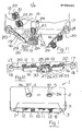
- Fig. 1 is a perspective view of a cleaning device according to the invention,
- Fig. 2 is a perspective view of the cleaning device of Fig. 1 with portion of the housing removed,
- Fig. 3 is a partly-cut away perspective view of the cleaning device of Fig. 1,
- Fig. 4 is a plan view of the cleaning device of Fig. 1,
- Fig. 5 is an underneath plan view of the cleaning device of Fig. 1,
- Fig. 6 is an exploded perspective view of the device of Fig. 1,
- Fig. 7 is a plan view of a detail of the device of Fig. 1,
- Fig. 8 is an underneath plan view of the detail of Fig. 6,
- Fig. 9 is a perspective view of another portion of the cleaning device of Fig. 1,
- Fig. 10 is a perspective view of a further portion of the device of Fig. 1. and
- Fig. 11 is a perspective view of the portion of Fig. 10 in a different position.
- Referring to the drawings, there is provided a cleaning device according to the invention indicated generally by the
reference numeral 1 for cleaning the sound head, capstan and pinch roller assembly, and other elements, (none of which are shown) in the tape path of a cassette player recorder (also not shown). Thedevice 1 comprises acassette housing 2 of injection moulded plastics material for engaging a cassette receiving area of the cassette player recorder. Thehousing 2 is formed in twohalves 3 and is substantially similar to a conventional tape cassette housing.Openings 4 and 5 are provided in eachralf 3 of thehousing 2 to accommodate the feed and take-up spindles respectively which are provided in the cassette receiving area of the cassette player recorder. An opening 7 is provided in thefront portion 8 of thedevice 1 which, in use, abuts the sound head, capstan pinch rollers assembly and other elements of the player. A main cleaning means, in this case abrush member 10 for cleaning the sound head is provided in the opening 7. Secondary cleaning means, namely,brush members housing 2 for driving thebrush members - The secondary cleaning means comprises a pair of
elongated carrier members 16 which are pivotal onshafts 17 extending between thehalves 3 of thehousing 2 and moulded integrally with each half. Eachcarrier member 16 is of injection moulded plastics material, and comprises a bearingmember 18 which pivotally engages theshafts 17. A pair of rebatedrecesses 19 are provided to slidably and releasably support thebrush members flexible portion 20 joins the bearingmember 18 with the recessedportion 19. Eachbrush member base member 21 withsoft bristles 22 extending therefrom. Some of thebristles 22 are of electrically conductive material. Eachbase member 21 slidably engages arecess 19. - A
support member 23 of injection moulded plastics material for supporting the soundhead brush member 10 is mounted on apivot shaft 24 for oscillating motion of themember 23. The shaft is formed in two halves, one being formed integrally on eachhalf 3 of thehousing 2. Thebrush member 10 is similar to thebrush members related recess 19 is provided in thesupport member 23 to slidably, releasably receive thebase member 21 of thebrush member 10. Thesupport member 23 comprises a central partlycircular bearing member 25 which engages theshaft 24 with a snap-on action. Theportions 26 of the bearingmember 25 each terminate in a thickenedportion 27 to ensure a snap-on fit on theshaft 24. A pair ofslots 28 are provided on each side of thesupport member 23 to engagecorresponding pivot members 29 on the free ends of eachcarrier member 16 to facilitate slidable and pivotal movement of thesupport member 23 with thepivot members 29, so that as thesupport member 23 oscillates, thecarrier members 16 are pivoted alternatively inwardly and outwardly, so that thebrush members members 30 extending from thesupport member 23 engage the drive means for oscillating thesupport 23 as will now be described. - The drive transmission means 14 comprises a drive member which in this case is provided by a
drive gear 33 rotatably mounted in the housing. A pair of projectingrings 34 extending inwardly of eachopening 5 in thehousing 2 rotatably engages correspondingrecesses 35 in abore 36 of thegear 33. Inwardly directed pins 37 act as splines to engage corresponding splines on the take-up spindle (not shown) of the cassette player recorder. On one side of adisc 38 extending around one end of thegear 33 is provided aneccentric ring 51 which will be described below. On the other side,gear teeth 39 are provided to engagecorresponding gear teeth 40 on anintermediate gear 41. Asmaller gear 42 integrally moulded with thegear 41 engages aninternal ring gear 43 of one of a pair ofmeshing gear members gear members halves 3 of thehousing 2 rotatably support theintermediate gear 41. A pair ofring portions 48 extending from eachhalf 3 of thehousing 2 rotatably engages correspondingrims 50 on the meshing gears 44 and 45. As can be seen in Fig. 8 the meshing gears 46 extend over only portion of the width of the outer periphery of therims 50 of eachmeshing gear Intermittent teeth 52 extend the full width of therims 50. Theseintermittent teeth 52 are provided to engage therearwardly extending members 30 of thesupport member 23, so that on rotation of the meshing gears 44 and 45 themembers 30 are alternatively struck by theintermittent teeth 52, thereby causing thesupport member 23 to oscillate. This in turn causes thecarrier members 16 to pivot. Theteeth 52 are positioned so that between each stroke of the support member there is a pause. In other words, the strokes are intermittent. Where a solvent is used on the brush members, this pause permits the solvent to soak into the dirt, thus making it easier to remove on the next stroke of the cleaning member. For ease of assembly, one tooth is omitted in theexternal gear ring 46 and a correspondingdouble tooth 53 is provided. The meshing gears 44 and 45 are identical, and accordingly, during assembly, they are assembled with thedouble tooth 53 engaging the portion with the missing tooth. This ensures that theintermittent teeth 52 are synchronised so that themembers 30 are alternatively struck. - Returning now to the
eccentric ring 51, this drives a reciprocatingmember 55 of injection moulded plastics material which at one end has abearing ring 56 in rotatable engagement with theeccentric ring 51. Aring memebr 57 is provided at the other end of the reciprocatingmember 55 which, in use, encircles the feed spindle (not shown) of the cassette player recorder. A plurality offlexible members 58 with inwardly directedtongues 59 extend inwardly fromposts 60 arranged around thering member 57. Thetongues 59 as the reciprocatingmember 55 reciprocates wipe across the splines of the feed spindle, thereby causing it to rotate intermittently. Aslot 61 in themember 55 engages aspud 63 integrally moulded with onehalf 3 of thehousing 2 to constrain themember 55 to move with reciprocating action. - In use, the
device 1 is mounted in the cassette receiving area of a cassette player recorder, so that thedrive gear 33 engages the take-up spindle of the cassette player recorder. The play button of the cassette player recorder is activated. As the take-up-spindle rotates thedrive gear 33 rotates with it, thus rotating the meshing gears 44 and 45 through theintermediate gears gears intermittent teeth 52 to alternatively strike the rearwardly directedmembers 30 thereby oscillating thesupport member 23 and in turn thesound head brush 10. The oscillating motion of thesupport member 23 causes thecarrier member 16 to pivot, thus wiping the capstan and pinch roller assembly with thebrush members drive gear 33 also causes the reciprocatingmember 55 to reciprocate, thereby intermittently driving the feed spindle by means of theflexible members 58. Thus, once the feed spindle is at least intermittently driven, the cassette player recorder continues to operate, thereby continuing the cleaning action. In general, a cleaning fluid would normally be applied to the brush members, prior to inserting the device in the cassette player recorder. - Should it be necessary to replace any of the brush members, this can readily easily be achieved by pulling out the
support member 23 through the opening 7. Thus, the bearingmember 25 of thesupport member 23 is disengaged from theshaft 24. This in turn, moves thecarrier members 16 out through the opening 4 as can be seen in Fig. 11. Thebrush members support member 23 in through the opening 7, thebearing.member 25 snaps on to theshaft 24 and the device is ready again for operation. - It has been found that by using relatively soft long bristles in the brush members a superior cleaning action is achieved. This is particularly noticeable in the case of cassette player recorders where the sound head is protected by guides to guide the tape across the sound head. The relatively long bristles are capable of penetrating into the recesses, corners and crevices formed between the edges of the sound head and the guide means.
- Furthermore, the use of relatively long bristles causes the bristles to fan out when abutting either the sound head, the capstan and pinch roller assembly, and other elements of the device, which in turn causes a considerably greater surface area of these elements to be cleaned than has been possible in devices known heretofore. Thus, dirt which builds up on the elements on both sides of the tape path is removed. Further, where the bristles are relatively soft, they fan out better.
- Furthermore, by virtue of the fact that an intermediate gear is disposed between the meshing gears and the drive gear, a considerable gear ratio reduction is achieved. This thereby causes the brushes to rotate relatively slowly, and accordingly with considerably greater cleaning force.
- Further, by virtue of the fact that a reciprocating member is used to only intermittently drive the feed spindle, considerably more energy is available for cleaning than in devices known heretofore, where a considerable amount of energy is utilised in merely rotating the feed spindle.
- It will be appreciated that while particular arrangements of reciprocating member have been used to intermittently drive the feed spindle, any other suitable intermittent drive means could be used without departing from the scope of the invention. For example, the ring member supporting the flexible members could be dispensed with, and in certain cases, only one flexible member may be provided to wipe past the splines of the feed spindle. Indeed, it will be appreciated that flexible members could be dispensed with if desired.
- It will also of course be appreciated that the reciprocating member could be driven from any other suitable gear.
- Additionally, it will be appreciated that other drive tranmission means besides those described could be used. For example, it is envisaged in certain cases that the oscillating motion of the support member could be achieved by a single gear member, which could drive, for example, a linear gear rack backwards and forwards.
- Further, it will be appreciated that a support member of any other construction could be used for supporting the brush member for the sound head. Indeed, it will, of course, be appreciated that any suitable cleaning means besides a brush member could be used for cleaning the sound head, and similarly, other suitable cleaning means for cleaning the capstan and pinch roller assembly and other elements could be used without departing from the scope of the invention. It will, of course, be appreciated that where brush members are used, it is not necessary that they be releasably mounted. Neither, is it necessary that the support member should be releasably mounted. Furthermore, it is not necessary that the main cleaning means be movable, although this is preferable.
- It will also of course be appreciated that while a particular type of housing has been described which is substantially similar to a cassette tape housing, any other suitable shape or construction of housing could be provided. In fact, in certain cases, it is envisaged that the housing could be provided merely by a base member or a framework on which the various members would be mounted and supported. Further, it is envisaged that other constructions of carrier members could be provided for supporting the brush members for cleaning the capstan and pinch roller assembly. Indeed, it will be appreciated that it is not necessary that these members should be pivoted, once they are movable at all, that is εufficient to provide active cleaning of the elements in the tape path. For example, the carrier members could be slidably moveable with a type of reciprocating action backwards and forwards across the front opening of the cassette housing or in and out if desired. It will also of course be appreciated that it is not necessary to provide two brushes on each carrier member, and in certain cases, it is envisaged that the support member and brush member for the sound head may be dispensed with altogether, and in other cases it is envisaged that it may be mounted on a single carrier member, which would reciprocate backwards and forwards across the opening. In which case, brush members for cleaning the other elements could also be provided on such a carrier member. Needless to say, it will be appreciated that while the housing and components of the cleaning device have been described as being of injection moulded plastics material, they could be of any other suitable material, and indeed, where of plastics material, they could be formed by other means besides injection moulding, for example, fabrication or the like.
- It is also envisaged that where meshing gears with intermediate teeth are used, these could be driven directly from the drive gear without the need for an intermediate gear. In fact, in certain cases, it will be appreciated that a single gear would be adequate for oscillating the support member, if the support member were biased towards the gear. In fact, it will of course be appreciated that all that is necessary is one single member to strike the support member, and in which case the support member would oscillate once for each revolution of the gear.
- While the brush members have been described as having electrically conductive bristles this is not necessary. They may be dispensed with altogether or in certain cases other electrically conductive means for removing the static electric charges could be used.
Claims (12)
Priority Applications (1)
| Application Number | Priority Date | Filing Date | Title |
|---|---|---|---|
| AT86301288T ATE60685T1 (en) | 1985-02-25 | 1986-02-24 | CLEANING DEVICE FOR A CASSETTE RECORDER. |
Applications Claiming Priority (2)
| Application Number | Priority Date | Filing Date | Title |
|---|---|---|---|
| IE46185 | 1985-02-25 | ||
| IE461/85A IE57610B1 (en) | 1985-02-25 | 1985-02-25 | A cleaning device |
Publications (3)
| Publication Number | Publication Date |
|---|---|
| EP0193367A2 true EP0193367A2 (en) | 1986-09-03 |
| EP0193367A3 EP0193367A3 (en) | 1988-01-27 |
| EP0193367B1 EP0193367B1 (en) | 1991-01-30 |
Family
ID=11012975
Family Applications (1)
| Application Number | Title | Priority Date | Filing Date |
|---|---|---|---|
| EP86301288A Expired - Lifetime EP0193367B1 (en) | 1985-02-25 | 1986-02-24 | A cleaning device for a cassette recorder |
Country Status (5)
| Country | Link |
|---|---|
| US (1) | US4698712A (en) |
| EP (1) | EP0193367B1 (en) |
| AT (1) | ATE60685T1 (en) |
| DE (1) | DE3677234D1 (en) |
| IE (1) | IE57610B1 (en) |
Cited By (7)
| Publication number | Priority date | Publication date | Assignee | Title |
|---|---|---|---|---|
| EP0287689A1 (en) * | 1987-04-19 | 1988-10-26 | Hans Müller | Cleaning cassette |
| EP0309398A1 (en) * | 1987-09-21 | 1989-03-29 | Manfred Baumann | Cleaning cassette for a cassette tape apparatus |
| US4851945A (en) * | 1986-10-10 | 1989-07-25 | Joseph F. Fritsch | Demagnetizing device having an oscillating permanent magnet |
| GB2232000A (en) * | 1989-02-18 | 1990-11-28 | Flintlock Limited | Cleaner for cassette player recorder machines |
| US5021911A (en) * | 1987-06-23 | 1991-06-04 | Automation Facilities Limited | Cleaning cassette |
| GB2239731A (en) * | 1989-12-06 | 1991-07-10 | Joseph Frederick Fritsch | A cleaning device |
| EP0439375A2 (en) * | 1990-01-26 | 1991-07-31 | Joseph Frederick Fritsch | A treatment device |
Families Citing this family (12)
| Publication number | Priority date | Publication date | Assignee | Title |
|---|---|---|---|---|
| US4843508A (en) * | 1987-06-10 | 1989-06-27 | Perfectdata Corporation | Cleaning cartridge for cleaning the drive head/drive wheel of a cartridge tape drive system |
| US4918557A (en) * | 1988-07-18 | 1990-04-17 | Benjamin Lee | Cleaner for magnetic head of tape recorder |
| US5047887A (en) * | 1989-12-28 | 1991-09-10 | Tandy Corporation | Method and apparatus for cleaning the tape head and tape path of a video cassette recorder using a wetted cleaning tape |
| US5113301A (en) * | 1990-12-04 | 1992-05-12 | Huang Ku Di | Structure of tape player/recorder magnetic head cleaner |
| US5355269A (en) * | 1992-11-16 | 1994-10-11 | Allsop, Inc. | Cleaning apparatus for a cassette player |
| US5461529A (en) * | 1994-01-04 | 1995-10-24 | Allsop, Inc. | Video player/recorder head drum cleaning device |
| US5671108A (en) * | 1995-08-29 | 1997-09-23 | Allsop, Inc. | Tape drive cleaner |
| US6097572A (en) * | 1998-01-29 | 2000-08-01 | Geneva Group Of Companies, Inc. | Tape drive head cleaning cartridge having a cleaning element with cleaning segments extending above and below a cleaning tape |
| US6292330B1 (en) | 1998-01-29 | 2001-09-18 | Geneva Group Of Companies, Inc. | Magnetic head cleaning cartridge with displaceable head receiver |
| US6038111A (en) * | 1998-01-29 | 2000-03-14 | Geneva Group Of Companies, Inc. | Cartridge having brushes above and below a cleaning tape for cleaning the reciprocating read/write head of a magnetic tape player and/or recorder |
| US6021026A (en) * | 1998-04-08 | 2000-02-01 | Storage Technology Corporation | Cleaning cartridge |
| JP2006053898A (en) * | 2004-07-15 | 2006-02-23 | Rohm Co Ltd | Overcurrent protection circuit and voltage generation circuit and electronic equipment using it |
Citations (5)
| Publication number | Priority date | Publication date | Assignee | Title |
|---|---|---|---|---|
| US4272796A (en) * | 1979-06-29 | 1981-06-09 | Kraco Enterprises, Inc. | Automatic cassette cleaner |
| GB2072920A (en) * | 1980-03-27 | 1981-10-07 | Cambrasound Ltd | Cleaner for a tape cassette player |
| FR2519457A1 (en) * | 1982-01-07 | 1983-07-08 | Allsop Inc | CLEANING ASSEMBLY FOR CABESTAN AND PRESS ROLL OF A READING AND / OR RECORDING APPARATUS |
| US4442468A (en) * | 1980-10-24 | 1984-04-10 | Allsop, Inc. | Cassette cleaning device |
| EP0114115A2 (en) * | 1983-01-17 | 1984-07-25 | Peter Robert Stanton | Tape recorder cleaner |
Family Cites Families (1)
| Publication number | Priority date | Publication date | Assignee | Title |
|---|---|---|---|---|
| JPS586519A (en) * | 1981-07-01 | 1983-01-14 | Nagaoka:Kk | Cleaner for cassette tape player |
-
1985
- 1985-02-25 IE IE461/85A patent/IE57610B1/en not_active IP Right Cessation
-
1986
- 1986-02-24 US US06/832,202 patent/US4698712A/en not_active Expired - Lifetime
- 1986-02-24 AT AT86301288T patent/ATE60685T1/en not_active IP Right Cessation
- 1986-02-24 EP EP86301288A patent/EP0193367B1/en not_active Expired - Lifetime
- 1986-02-24 DE DE8686301288T patent/DE3677234D1/en not_active Expired - Lifetime
Patent Citations (5)
| Publication number | Priority date | Publication date | Assignee | Title |
|---|---|---|---|---|
| US4272796A (en) * | 1979-06-29 | 1981-06-09 | Kraco Enterprises, Inc. | Automatic cassette cleaner |
| GB2072920A (en) * | 1980-03-27 | 1981-10-07 | Cambrasound Ltd | Cleaner for a tape cassette player |
| US4442468A (en) * | 1980-10-24 | 1984-04-10 | Allsop, Inc. | Cassette cleaning device |
| FR2519457A1 (en) * | 1982-01-07 | 1983-07-08 | Allsop Inc | CLEANING ASSEMBLY FOR CABESTAN AND PRESS ROLL OF A READING AND / OR RECORDING APPARATUS |
| EP0114115A2 (en) * | 1983-01-17 | 1984-07-25 | Peter Robert Stanton | Tape recorder cleaner |
Cited By (13)
| Publication number | Priority date | Publication date | Assignee | Title |
|---|---|---|---|---|
| US4851945A (en) * | 1986-10-10 | 1989-07-25 | Joseph F. Fritsch | Demagnetizing device having an oscillating permanent magnet |
| EP0287689A1 (en) * | 1987-04-19 | 1988-10-26 | Hans Müller | Cleaning cassette |
| US5021911A (en) * | 1987-06-23 | 1991-06-04 | Automation Facilities Limited | Cleaning cassette |
| EP0309398A1 (en) * | 1987-09-21 | 1989-03-29 | Manfred Baumann | Cleaning cassette for a cassette tape apparatus |
| GB2232000B (en) * | 1989-02-18 | 1993-07-07 | Flintlock Limited | Cleaner for cassette player recorder machines |
| GB2232811A (en) * | 1989-02-18 | 1990-12-19 | Flintlock Limited | Cleaner for cassette player recorder machines |
| GB2232000A (en) * | 1989-02-18 | 1990-11-28 | Flintlock Limited | Cleaner for cassette player recorder machines |
| GB2232811B (en) * | 1989-02-18 | 1993-07-07 | Flintlock Limited | Cleaner for cassette player recorder machines |
| GB2239731A (en) * | 1989-12-06 | 1991-07-10 | Joseph Frederick Fritsch | A cleaning device |
| GB2239731B (en) * | 1989-12-06 | 1994-03-23 | Joseph Frederick Fritsch | A cleaning device |
| EP0439375A2 (en) * | 1990-01-26 | 1991-07-31 | Joseph Frederick Fritsch | A treatment device |
| EP0439375A3 (en) * | 1990-01-26 | 1992-08-05 | Joseph Frederick Fritsch | A treatment device |
| US5309307A (en) * | 1990-01-26 | 1994-05-03 | Fritsch Joseph F | Timer controlled device for cleaning a moving head and/or a drum of a playback and/or recording unit |
Also Published As
| Publication number | Publication date |
|---|---|
| ATE60685T1 (en) | 1991-02-15 |
| US4698712A (en) | 1987-10-06 |
| IE57610B1 (en) | 1993-01-27 |
| EP0193367A3 (en) | 1988-01-27 |
| DE3677234D1 (en) | 1991-03-07 |
| IE850461L (en) | 1986-08-25 |
| EP0193367B1 (en) | 1991-01-30 |
Similar Documents
| Publication | Publication Date | Title |
|---|---|---|
| EP0193367B1 (en) | A cleaning device for a cassette recorder | |
| US4594629A (en) | Cassette cleaning device | |
| US4272796A (en) | Automatic cassette cleaner | |
| CA1094680A (en) | Cleaner for a playing head of a cassette player | |
| RU2318472C2 (en) | Toothbrush with arbitrary circular motion of head | |
| EP0210787B1 (en) | A video cleaning device | |
| EP0114115A2 (en) | Tape recorder cleaner | |
| GB2173033A (en) | Cleaning device for cassette recorder/player units | |
| US5021912A (en) | Apparatus for cleaning the recording/playing head, capstan and pinch roller of a cassette type audio recorder/player | |
| US6028751A (en) | Cleaning device for cleaning components of a video unit and for cleaning outside a tape path area | |
| US4855855A (en) | Tape recorder head cleaner | |
| US4894743A (en) | Replaceable cleaner/drive members for a tape drive machine | |
| US5355269A (en) | Cleaning apparatus for a cassette player | |
| US5671108A (en) | Tape drive cleaner | |
| US5353184A (en) | Cassette cleaner having both capstan and pinch roller elements | |
| US7389557B2 (en) | Toothbrush | |
| IE80870B1 (en) | A demagnetizing device | |
| US5420737A (en) | Cleaning apparatus for a tape drive machine with a mechanism to select between a capstan cleaning configuration and a head cleaning configuration | |
| JPS62155812A (en) | Rotary brush | |
| CN114916862B (en) | Device with scraping bar capable of reciprocating motion and floor sweeping machine | |
| JPH09327424A (en) | Rotary sweeping member of vacuum cleaner | |
| US5113301A (en) | Structure of tape player/recorder magnetic head cleaner | |
| CN218419716U (en) | Movable scraping strip mechanism and floor washing machine | |
| JPH0445127Y2 (en) | ||
| RU1771828C (en) | Device for long-dimension articles clearing |
Legal Events
| Date | Code | Title | Description |
|---|---|---|---|
| PUAI | Public reference made under article 153(3) epc to a published international application that has entered the european phase |
Free format text: ORIGINAL CODE: 0009012 |
|
| AK | Designated contracting states |
Kind code of ref document: A2 Designated state(s): AT BE CH DE FR GB IT LI LU NL SE |
|
| PUAL | Search report despatched |
Free format text: ORIGINAL CODE: 0009013 |
|
| AK | Designated contracting states |
Kind code of ref document: A3 Designated state(s): AT BE CH DE FR GB IT LI LU NL SE |
|
| 17P | Request for examination filed |
Effective date: 19880630 |
|
| 17Q | First examination report despatched |
Effective date: 19881229 |
|
| GRAA | (expected) grant |
Free format text: ORIGINAL CODE: 0009210 |
|
| AK | Designated contracting states |
Kind code of ref document: B1 Designated state(s): AT BE CH DE FR GB IT LI LU NL SE |
|
| PG25 | Lapsed in a contracting state [announced via postgrant information from national office to epo] |
Ref country code: IT Free format text: LAPSE BECAUSE OF FAILURE TO SUBMIT A TRANSLATION OF THE DESCRIPTION OR TO PAY THE FEE WITHIN THE PRE;WARNING: LAPSES OF ITALIAN PATENTS WITH EFFECTIVE DATE BEFORE 2007 MAY HAVE OCCURRED AT ANY TIME BEFORE 2007. THE CORRECT EFFECTIVE DATE MAY BE DIFFERENT FROM THE ONE RECORDED.SCRIBED TIME-LIMIT Effective date: 19910130 Ref country code: AT Effective date: 19910130 |
|
| REF | Corresponds to: |
Ref document number: 60685 Country of ref document: AT Date of ref document: 19910215 Kind code of ref document: T |
|
| ET | Fr: translation filed | ||
| PG25 | Lapsed in a contracting state [announced via postgrant information from national office to epo] |
Ref country code: LU Free format text: LAPSE BECAUSE OF NON-PAYMENT OF DUE FEES Effective date: 19910228 |
|
| REF | Corresponds to: |
Ref document number: 3677234 Country of ref document: DE Date of ref document: 19910307 |
|
| PLBE | No opposition filed within time limit |
Free format text: ORIGINAL CODE: 0009261 |
|
| STAA | Information on the status of an ep patent application or granted ep patent |
Free format text: STATUS: NO OPPOSITION FILED WITHIN TIME LIMIT |
|
| 26N | No opposition filed | ||
| PGFP | Annual fee paid to national office [announced via postgrant information from national office to epo] |
Ref country code: CH Payment date: 19920217 Year of fee payment: 7 |
|
| PGFP | Annual fee paid to national office [announced via postgrant information from national office to epo] |
Ref country code: BE Payment date: 19920302 Year of fee payment: 7 |
|
| PG25 | Lapsed in a contracting state [announced via postgrant information from national office to epo] |
Ref country code: BE Effective date: 19930228 Ref country code: CH Effective date: 19930228 Ref country code: LI Effective date: 19930228 |
|
| BERE | Be: lapsed |
Owner name: FRITSCH JOSEPH FREDERICK Effective date: 19930228 Owner name: FRITSCH ROXANNE YVONNE Effective date: 19930228 |
|
| REG | Reference to a national code |
Ref country code: CH Ref legal event code: PL |
|
| EAL | Se: european patent in force in sweden |
Ref document number: 86301288.6 |
|
| PGFP | Annual fee paid to national office [announced via postgrant information from national office to epo] |
Ref country code: SE Payment date: 20010205 Year of fee payment: 16 |
|
| PGFP | Annual fee paid to national office [announced via postgrant information from national office to epo] |
Ref country code: DE Payment date: 20010221 Year of fee payment: 16 |
|
| PGFP | Annual fee paid to national office [announced via postgrant information from national office to epo] |
Ref country code: NL Payment date: 20010227 Year of fee payment: 16 |
|
| REG | Reference to a national code |
Ref country code: GB Ref legal event code: IF02 |
|
| PG25 | Lapsed in a contracting state [announced via postgrant information from national office to epo] |
Ref country code: SE Free format text: LAPSE BECAUSE OF NON-PAYMENT OF DUE FEES Effective date: 20020225 |
|
| PGFP | Annual fee paid to national office [announced via postgrant information from national office to epo] |
Ref country code: FR Payment date: 20020227 Year of fee payment: 17 |
|
| PG25 | Lapsed in a contracting state [announced via postgrant information from national office to epo] |
Ref country code: NL Free format text: LAPSE BECAUSE OF NON-PAYMENT OF DUE FEES Effective date: 20020901 |
|
| PG25 | Lapsed in a contracting state [announced via postgrant information from national office to epo] |
Ref country code: DE Free format text: LAPSE BECAUSE OF NON-PAYMENT OF DUE FEES Effective date: 20020903 |
|
| EUG | Se: european patent has lapsed |
Ref document number: 86301288.6 |
|
| NLV4 | Nl: lapsed or anulled due to non-payment of the annual fee |
Effective date: 20020901 |
|
| PG25 | Lapsed in a contracting state [announced via postgrant information from national office to epo] |
Ref country code: FR Free format text: LAPSE BECAUSE OF NON-PAYMENT OF DUE FEES Effective date: 20031031 |
|
| REG | Reference to a national code |
Ref country code: FR Ref legal event code: ST |
|
| PGFP | Annual fee paid to national office [announced via postgrant information from national office to epo] |
Ref country code: GB Payment date: 20040213 Year of fee payment: 19 |
|
| PG25 | Lapsed in a contracting state [announced via postgrant information from national office to epo] |
Ref country code: GB Free format text: LAPSE BECAUSE OF NON-PAYMENT OF DUE FEES Effective date: 20050224 |
|
| GBPC | Gb: european patent ceased through non-payment of renewal fee |
Effective date: 20050224 |