EP0192573B1 - System for plasma cutting or welding incorporating a timer - Google Patents
System for plasma cutting or welding incorporating a timer Download PDFInfo
- Publication number
- EP0192573B1 EP0192573B1 EP86400343A EP86400343A EP0192573B1 EP 0192573 B1 EP0192573 B1 EP 0192573B1 EP 86400343 A EP86400343 A EP 86400343A EP 86400343 A EP86400343 A EP 86400343A EP 0192573 B1 EP0192573 B1 EP 0192573B1
- Authority
- EP
- European Patent Office
- Prior art keywords
- torch
- cutting
- flow
- gas
- duration
- Prior art date
- Legal status (The legal status is an assumption and is not a legal conclusion. Google has not performed a legal analysis and makes no representation as to the accuracy of the status listed.)
- Expired
Links
- 238000005520 cutting process Methods 0.000 title claims description 53
- 238000003466 welding Methods 0.000 title claims description 15
- 238000010891 electric arc Methods 0.000 claims description 15
- 238000001816 cooling Methods 0.000 claims description 7
- 230000000694 effects Effects 0.000 claims description 6
- 238000006073 displacement reaction Methods 0.000 claims 1
- 235000010599 Verbascum thapsus Nutrition 0.000 description 64
- 239000007789 gas Substances 0.000 description 47
- 238000004804 winding Methods 0.000 description 46
- 239000003990 capacitor Substances 0.000 description 9
- 239000004020 conductor Substances 0.000 description 6
- 230000005284 excitation Effects 0.000 description 6
- 244000178289 Verbascum thapsus Species 0.000 description 5
- 239000002826 coolant Substances 0.000 description 3
- 238000009434 installation Methods 0.000 description 3
- 238000000034 method Methods 0.000 description 3
- 230000001960 triggered effect Effects 0.000 description 3
- 238000010438 heat treatment Methods 0.000 description 2
- 239000007788 liquid Substances 0.000 description 2
- 239000000463 material Substances 0.000 description 2
- 230000037452 priming Effects 0.000 description 2
- 230000000284 resting effect Effects 0.000 description 2
- 230000002159 abnormal effect Effects 0.000 description 1
- 230000003416 augmentation Effects 0.000 description 1
- 230000008033 biological extinction Effects 0.000 description 1
- 230000015572 biosynthetic process Effects 0.000 description 1
- 230000006835 compression Effects 0.000 description 1
- 238000007906 compression Methods 0.000 description 1
- 230000002950 deficient Effects 0.000 description 1
- 230000003111 delayed effect Effects 0.000 description 1
- 230000006866 deterioration Effects 0.000 description 1
- 230000005611 electricity Effects 0.000 description 1
- 229940082150 encore Drugs 0.000 description 1
- 230000005281 excited state Effects 0.000 description 1
- 230000000977 initiatory effect Effects 0.000 description 1
- 238000002955 isolation Methods 0.000 description 1
- 238000012423 maintenance Methods 0.000 description 1
- 238000000926 separation method Methods 0.000 description 1
- 238000011144 upstream manufacturing Methods 0.000 description 1
- XLYOFNOQVPJJNP-UHFFFAOYSA-N water Substances O XLYOFNOQVPJJNP-UHFFFAOYSA-N 0.000 description 1
Images


Classifications
-
- H—ELECTRICITY
- H05—ELECTRIC TECHNIQUES NOT OTHERWISE PROVIDED FOR
- H05H—PLASMA TECHNIQUE; PRODUCTION OF ACCELERATED ELECTRICALLY-CHARGED PARTICLES OR OF NEUTRONS; PRODUCTION OR ACCELERATION OF NEUTRAL MOLECULAR OR ATOMIC BEAMS
- H05H1/00—Generating plasma; Handling plasma
- H05H1/24—Generating plasma
- H05H1/26—Plasma torches
- H05H1/32—Plasma torches using an arc
- H05H1/34—Details, e.g. electrodes, nozzles
- H05H1/36—Circuit arrangements
-
- H—ELECTRICITY
- H05—ELECTRIC TECHNIQUES NOT OTHERWISE PROVIDED FOR
- H05H—PLASMA TECHNIQUE; PRODUCTION OF ACCELERATED ELECTRICALLY-CHARGED PARTICLES OR OF NEUTRONS; PRODUCTION OR ACCELERATION OF NEUTRAL MOLECULAR OR ATOMIC BEAMS
- H05H1/00—Generating plasma; Handling plasma
- H05H1/24—Generating plasma
- H05H1/26—Plasma torches
- H05H1/28—Cooling arrangements
-
- H—ELECTRICITY
- H05—ELECTRIC TECHNIQUES NOT OTHERWISE PROVIDED FOR
- H05H—PLASMA TECHNIQUE; PRODUCTION OF ACCELERATED ELECTRICALLY-CHARGED PARTICLES OR OF NEUTRONS; PRODUCTION OR ACCELERATION OF NEUTRAL MOLECULAR OR ATOMIC BEAMS
- H05H1/00—Generating plasma; Handling plasma
- H05H1/24—Generating plasma
- H05H1/26—Plasma torches
- H05H1/32—Plasma torches using an arc
- H05H1/34—Details, e.g. electrodes, nozzles
- H05H1/3494—Means for controlling discharge parameters
Definitions
- the present invention relates to a plasma welding or cutting system, of the type comprising an ignition torch by cuort-circuit with fixed electrode and movable nozzle, means for supplying gas to the torch to provide it with a strong plasma gas flow rate, as well as electrical supply means for the torch to generate, maintain or cut an electric arc of plasma welding or cutting, the nozzle being mounted with axial movement until contact with the electrode against the action of an elastic return means towards a position of maximum mutual spacing corresponding to normal operation.
- the nozzle is thus mounted to slide freely in the body of the torch, so as to come into contact with the electrode when the torch is applied against a workpiece.
- an arc lights up between the electrode and the nozzle making it possible to initiate and maintain an electric arc between these parts, said arc being transferred to the part to be cut.
- the plasma gas continues to be injected into the torch as long as the system is kept energized. This makes it possible in particular to cool the torch after use.
- the system is not very economical, since plasma gas is also injected in the absence of an electric arc. In addition, it is particularly troublesome during ignition by short circuit, because it requires a large force to achieve it. If the workpiece is thin and cantilevered, ignition becomes very difficult.
- the system according to the invention makes it possible to avoid this drawback.
- it comprises timing means connected, on the one hand, to the electrical supply means of the torch, and on the other hand, to the gas supply means of the torch, said timing means being sensitive upon cutting off the electric arc of the torch and controlling the stopping or reduction of said gas flow after a predetermined time interval following the cutting off of the electric arc, so as to cool the torch during said interval of time.
- said time delay means comprise means for adjusting the predetermined time interval.
- the system according to the invention is characterized in that the gas supply means comprise in particular a first solenoid valve, the opening or closing of which controls the passage of the plasma gas, the electrical circuit for controlling said solenoid valve being connected to the power supply means via the timing means.
- the gas supply means comprise in particular a first solenoid valve, the opening or closing of which controls the passage of the plasma gas, the electrical circuit for controlling said solenoid valve being connected to the power supply means via the timing means.
- the nozzle which is movable in the torch body can, for example, under the effect of the weight of the torch, slide in its housing and come to inadvertently start the ignition process of the arc, without deliberate action of the operator.
- the gas supply means include in particular a second solenoid valve with two flow rates.
- the electrical control circuit of which is connected to the electrical supply means the first flow corresponding to the phases to generate and maintain the electric arc, the second flow, lower than the first, corresponding to the phase in which the electric arc is cut while the installation is still energized, this flow rate scond is of sufficient value to keep the nozzle and the electrode away from each other, regardless of the position of the torch.
- the cutting of the plasma electric arc causes the passage from the normal flow to the low flow of the second solenoid valve, this low flow making it possible both to cool the electrode and the nozzle on the one hand, and to maintain the nozzle on its seat at a distance from the electrode, on the other hand.
- this second embodiment of the invention particularly applicable in the case where the second (low) flow rate of the second solenoid valve is not sufficient to properly cool the electrode and the nozzle, it is provided that the means of time delay are inserted between the control circuit of the second solenoid valve and the electrical supply means, the gas supply means being always open when the system is energized, so as to cool the torch using of the first gas flow from the second solenoid valve, when the electric arc is cut off, then maintaining the gap between the electrode and the nozzle using the second flow of the second solenoid valve.
- the user may wish to reactivate the torch also for the duration of the time delay, during which the gas flow is identical to the gas flow of the torch during the welding or cutting phase.
- the force to be exerted on the torch to cause the short circuit is much greater than when starting without gas flow or at low gas level. It is then found that the lighting of the torch is very difficult, in particular on a thin plate, in overhang.
- the invention provides, according to a preferred embodiment, two alternatives:
- the first in which the timer has a double duration, one short (or zero) corresponding to a short use of the torch, the other long, corresponding to a longer use of the torch. These durations are determined according to the material and its use.
- the second in which the time delay varies continuously according to the duration of use of the torch, up to a maximum threshold, whatever this duration of use.
- this time delay will have a duration of zero when the duration of the previous cutting step is less than a predetermined value.
- the duration of this time delay will be a function of the preceding cutting duration, without being able to exceed a maximum value defined experimentally as a function of the structure and the materials used in this torch.
- This maximum duration is that which makes it possible to reduce the temperature of the nozzle to a value of the order of ambient temperature, for the gas flow rate used with this torch.
- the function which defines the duration of the temperature will preferably be a function of the exponential type;
- the corresponding electrical circuit will preferably use the charge and / or discharge of a capacitor, triggered by the start of the cutting operation, to determine the duration of the time delay.
- the means necessary for these two alternatives are part of the means for adjusting the predetermined time interval.
- a terminal 45 of the secondary 33 of the transformer 31 is also connected to the part 7 by a circuit incorporating in series a thermal contact 46, opening in the event of an abnormal rise in temperature, placed in the windings of the main transformer 10, a contact 47 closing under the effect of a gas pressure, placed in the gas supply pipe of the torch, an excitation winding 48, associated with an impedance 49 (capacitor 50 and resistor 51 in parallel), this winding 48 controlling, in the excited state, the closing of the contact 43, the whole being connected, by a diode 52, to the terminal 24 of the inductor 23, while the negative terminal 18 is connected, by a diode 53, to the another terminal of the secondary 33 of the transformer 31.
- the terminal 22 of the inductor 23 is connected by a conductor 55 with resistance 56 to the terminal 45 of the secondary 33 of the transformer 31.
- the solenoid valve V together with the gas supply pipe (and the general gas supply tap, not shown), the gas supply means G.M.
- the arc is formed by the coming into mutual contact of the electrode 2, the nozzle 3 and the part 7.
- the auxiliary circuit 30 supplies, from the transformer 31, the winding 48 which is excited, via safety contacts 46 and 47 and short-circuit 2-3-7, which causes contact 43 of relay 48 to close, thus energizing windings 42 and 142, causing contact 15 to close of the main transformer 10, as well as the closing of the contact 86, so that the plasma gas reaches and flows into the torch through the passages 500 and 501.
- the spacing of the electrode 2 of the nozzle 3 forms the arc welding or cutting between electrode 2 and part 7 and thus establishes the welding or cutting current.
- Maintaining the excitation of the winding 48 is ensured by the voltage at the terminals 22-24 of the inductor 23, which depends on the existence of the welding or cutting current, this voltage ensuring the supply of the winding 48 via the conductor 55, the resistor 56, the safety contacts 46, 47 and the unidirectional element 52.
- the contact 43 opens, the winding 42 is also de-energized opening the contact 15.
- the winding 142 is also de-energized causing the delayed resting of the relay 86 and the closing of the solenoid valve V 1 , the winding of which 44 is no longer powered.
- the duration of the delay on closing V 1 varies between 5 and 15 seconds. This interval is determined experimentally according to the characteristics of the torch and its use.
- a control circuit (lamp 60 and unidirectional element 61) optically signals the correct state of the gas supply and the non-heating of the transformer 10.
- a lamp 62 connected in series with a unidirectional element 63 optically signals the good condition of the winding 42 and of its contact 15.
- the lamp 62 is in series with a bimetal switch 64, so that in normal operation this lamp 62 lights up dimly and goes out during '' a stop of operation.
- the lamp 62 will start to flash in the event that the winding 42 or the contact 15 are defective, due to the existence of a high open-circuit voltage across the terminals of the secondary 16 of the transformer 10.
- a sound device 65 in parallel on the lamp 62.
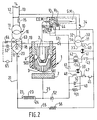
- FIG. 2 shows an alternative embodiment of the system of Figure 1, in which the same elements as those of Figure 1 have the same references.
- the winding 44 in this variant is part of the auxiliary control circuit 30.
- the CGM timing means are cons here constituted by a double flow solenoid valve V 2 controlled by the winding 84, connected in series with a timed switch 85.
- the ends of the winding 84 and the timed switch 85, not connected to each other, are connected in parallel on the winding 44 and across the secondary of the transformer 31.
- the first flow of the solenoid valve V 2 corresponds to the normal flow of the device, this flow being at least equal to the flow of the solenoid valve V 1 .
- the second flow rate of the solenoid valve V 2 is low, compared to the first and makes it possible to generate a calibrated gas leak.
- This calibrated gas leak has a sufficient value to allow the nozzle and the electrode to be kept at a distance, that is to say to keep the movable nozzle resting on its seat in the torch body 1.
- the value of this second flow is determined experimentally and the valve V 2 is chosen or adjusted so as to obtain said flow in its second position.
- the second flow (calibrated leak) will be such that it cannot allow both the creation and maintenance of a plasma arc as well as sufficient cooling of the torch.
- the start-up of the cutting circuit is identical to that described in FIG. 2.
- the contact 85 closes, which generates a “high flow rate” of gas during the cutting period.
- time t o the voltage on the negative input of the comparator amplifier A1 being greater than that on the positive input, the transistor T1 is blocked and the winding 242 is not energized.
- Switch 185 is open.
- the contact 85 also opens, which results in a de-excitation of the winding 84, the valve V2 immediately passing into the "low flow” position.
- a “high flow” of gas is thus maintained in the valve V 2 and in the nozzle after the end of the cutting step, the duration of this “high flow” being equal to the value of the timeout of the timed switch 385. As previously, this value does not generally exceed a few seconds.
- variable time delay is to provide a cooling time which is directly a function of the temperature of the torch after the previous cutting operation. For that. it is possible to record experimentally the heating curve of the torch (at a determined point thereof, for example near the electrode) as a function of the cutting time and to reproduce substantially the same curve for the variable time delay.
Landscapes
- Physics & Mathematics (AREA)
- Engineering & Computer Science (AREA)
- Plasma & Fusion (AREA)
- Spectroscopy & Molecular Physics (AREA)
- Plasma Technology (AREA)
- Arc Welding In General (AREA)
- Arc Welding Control (AREA)
- Acyclic And Carbocyclic Compounds In Medicinal Compositions (AREA)
Description
La presente invention concerne un système de soudage ou de coupage plasma, du type comprenant une torche à allumage part cuort-circuit à électrode fixe et à tuyère mobile, des moyens d'alimentation en gaz de la torche pour fournir à celle-ci un fort débit de gaz plasmagène, ainsi que des moyens d'alimentation électriques de la torche pour engendrer, maintenir ou couper un arc électrique de soudage ou de coupage plasma, la tuyère étant montée à débattement axial jusqu'au contact de l'électrode contre l'action d'un moyen élastique de rappel vers une position d'écartement mutuel maximal correspondant au fonctionnement normal.The present invention relates to a plasma welding or cutting system, of the type comprising an ignition torch by cuort-circuit with fixed electrode and movable nozzle, means for supplying gas to the torch to provide it with a strong plasma gas flow rate, as well as electrical supply means for the torch to generate, maintain or cut an electric arc of plasma welding or cutting, the nozzle being mounted with axial movement until contact with the electrode against the action of an elastic return means towards a position of maximum mutual spacing corresponding to normal operation.
Il est connu du brevet américain 3 242 305, un système comportant une torche plasma dans laquelle l'électrode et la tuyère sont refroidies par un courant de liquide tel que l'eau. Dans cette torche, l'électrode est mobile par rapport à la tuyère et au contact électrique de celle-ci lorsque la torche est au repos. Lors de la mise sous tension, ceci entraîne une mise sous pression du liquide de refroidissement par un mécanisme hydraulique qui entraîne la compression d'un ressort et la séparation de l'électrode et de la tuyère, créant ainsi un arc électrique et l'amorçage du gaz plasmagène injecté dans la torche lors de la mise en route de celle-ci. Dans cette torche, le fluide de refroidissement circule aussi longtemps que ledit système est sous tension, indépendamment de l'alimentation en gaz.It is known from American Patent 3,242,305, a system comprising a plasma torch in which the electrode and the nozzle are cooled by a stream of liquid such as water. In this torch, the electrode is movable relative to the nozzle and to the electrical contact thereof when the torch is at rest. When energized, this causes the coolant to be pressurized by a hydraulic mechanism which causes compression of a spring and separation of the electrode and the nozzle, thus creating an electric arc and initiation. plasma gas injected into the torch when it starts up. In this torch, the coolant circulates as long as said system is energized, regardless of the gas supply.
Il est connu du brevet français 2 385 483 de réaliser l'amorçage entre l'électrode et la tuyère par mise en court-circuit de celles-ci, ladite électrode étant vissée et mise au contact de la tuyère puis dévissée, l'écart entre l'électrode et la tuyère étant ensuite réglé à la valeur voulue. La torche décrite dans ce brevet comporte un système de refroidissement à l'aide d'un liquide circulant au niveau de l'électrode et de la tuyère. Cette circulation du fluide de refroidissement s'effectue lorsque le système est sous tension.It is known from French patent 2,385,483 to initiate priming between the electrode and the nozzle by short-circuiting the latter, said electrode being screwed and brought into contact with the nozzle then unscrewed, the difference between the electrode and the nozzle then being adjusted to the desired value. The torch described in this patent includes a cooling system using a liquid circulating at the level of the electrode and the nozzle. This circulation of the coolant takes place when the system is energized.
Il a été proposé dans le brevet français 2 562 748, une torche comportant une structure particulièrement bien adaptée à la mise en oeuvre de l'amorçage par court-circuit entre l'électrode et la tuyère. (On pourra se référer pour plus de détail concernant ce procédé d'allumage par court-circuit au brevet français 2 556 549.) Dans ce procédé, l'électrode et la tuyère sont montées à débattement axial jusqu'au contact mutuel, contre l'action d'un moyen élastique de rappel vers une position d'écartement mutuel maximal correspondant au fonctionnement normal.It has been proposed in French patent 2,562,748, a torch having a structure particularly well suited to the implementation of priming by short circuit between the electrode and the nozzle. (We can refer for more detail concerning this ignition process by short circuit to French patent 2,556,549.) In this process, the electrode and the nozzle are mounted with axial movement until mutual contact, against the action of an elastic return means towards a position of maximum mutual spacing corresponding to normal operation.
La tuyère est ainsi montée à coulissement libre dans le corps de la torche, de manière à venir en contact avec l'électrode lorsque la torche est appliquée contre une pièce. En dégageant la torche, un arc s'allume entre l'électrode et la tuyère, permettant d'amorcer et maintenir un arc électrique entre ces pièces, ledit arc étant transféré vers la pièce à découper.The nozzle is thus mounted to slide freely in the body of the torch, so as to come into contact with the electrode when the torch is applied against a workpiece. By releasing the torch, an arc lights up between the electrode and the nozzle, making it possible to initiate and maintain an electric arc between these parts, said arc being transferred to the part to be cut.
Lorsque l'arc électrique est coupé, le gaz plasmagène continue à être injecté dans la torche tant que le système est maintenu sous tension. Ceci permet d'assurer notamment le refroidissement de la torche après utilisation.When the electric arc is cut, the plasma gas continues to be injected into the torch as long as the system is kept energized. This makes it possible in particular to cool the torch after use.
Le système est peu économique, puisque l'on injecte également du gaz plasmagène en l'absence d'arc électrique. De plus, il se révèle particulièrement gênant lors de l'allumage par court-circuit, car il nécessite une force importante pour réaliser celui-ci. Si la pièce à couper est mince et en porte-à-faux, l'allumage devient très difficile.The system is not very economical, since plasma gas is also injected in the absence of an electric arc. In addition, it is particularly troublesome during ignition by short circuit, because it requires a large force to achieve it. If the workpiece is thin and cantilevered, ignition becomes very difficult.
Le système selon l'invention permet d'éviter cet inconvénient. Dans ce but, il comporte des moyens de temporisation reliés, d'une part, aux moyens d'alimentation électrique de la torche, et d'autre part, aux moyens d'alimentation en gaz de la torche, lesdits moyens de temporisation étant sensibles à la coupure de l'arc électrique de la torche et commandant l'arrêt ou la réduction dudit débit de gaz après un intervalle de temps prédéterminé suivant la coupure de l'arc électrique, de manière à assurer le refroidissement de la torche pendant ledit intervalle de temps.The system according to the invention makes it possible to avoid this drawback. To this end, it comprises timing means connected, on the one hand, to the electrical supply means of the torch, and on the other hand, to the gas supply means of the torch, said timing means being sensitive upon cutting off the electric arc of the torch and controlling the stopping or reduction of said gas flow after a predetermined time interval following the cutting off of the electric arc, so as to cool the torch during said interval of time.
Selon une variante de réalisation, lesdits moyens de temporisation comportent des moyens de réglage de l'intervalle de temps prédéterminé.According to an alternative embodiment, said time delay means comprise means for adjusting the predetermined time interval.
De préférence, le système selon l'invention est caractérisé en ce que les moyens d'alimentation en gaz comportent notamment une première électrovanne dont l'ouverture ou la fermeture commande le passage du gaz plasmagène, le circuit électrique de commande de ladite électrovanne étant connecté aux moyens d'alimentation électrique par l'intermédiaire des moyens de temporisation.Preferably, the system according to the invention is characterized in that the gas supply means comprise in particular a first solenoid valve, the opening or closing of which controls the passage of the plasma gas, the electrical circuit for controlling said solenoid valve being connected to the power supply means via the timing means.
Une telle solution est entièrement satisfaisante lorsque, en particulier, sont prévus des moyens du type ressort destinés à maintenir l'électrode et la tuyère à distance l'une de l'autre, de manière à éviter un contact intempestif entre-elles lorsque l'arrivée de gaz plasmagène est coupée après cette période de temporisation.Such a solution is entirely satisfactory when, in particular, means of the spring type are provided intended to keep the electrode and the nozzle at a distance from each other, so as to avoid inadvertent contact between them when the Plasma gas supply is cut off after this time-out period.
Toutefois, lorsque le maintien à distance de l'électrode et de la tuyère est assuré par le débit du gaz plasmagène lui-même, celui-ci plaque la tuyère sur son siège dans le corps de torche: la coupure du flux de gaz plasmagène fait apparaître un nouveau problème. La tuyère, qui est mobile dans le corps de torche peut, par exemple, sous l'effet du poids de la torche, coulisser dans son logement et venir démarrer intempestivement le processus d'allumage de l'arc, sans action délibérée de l'opérateur.However, when the distance between the electrode and the nozzle is ensured by the flow of the plasma gas itself, the latter presses the nozzle on its seat in the torch body: the plasma gas flow is cut off appear a new problem. The nozzle, which is movable in the torch body can, for example, under the effect of the weight of the torch, slide in its housing and come to inadvertently start the ignition process of the arc, without deliberate action of the operator.
Pour résoudre simultanément les deux problèmes ainsi posés, l'invention prévoit que les moyens d'alimentation en gaz comportent notamment une seconde électrovanne à deux débits. dont le circuit électrique de commande est connecté aux moyens d'alimentation électrique, le premier débit correspondant aux phases pour engendrer et maintenir l'arc électrique, le second débit, plus faible que le premier, correspondant à la phase dans laquelle l'arc électrique est coupé tandis que l'installation est toujours sous tension, ce scond débit ayant une valeur suffisante pour maintenir la tuyère et l'électrode à distance l'une de l'autre, quelle que soit la position de la torche.To simultaneously solve the two problems thus posed, the invention provides that the gas supply means include in particular a second solenoid valve with two flow rates. the electrical control circuit of which is connected to the electrical supply means, the first flow corresponding to the phases to generate and maintain the electric arc, the second flow, lower than the first, corresponding to the phase in which the electric arc is cut while the installation is still energized, this flow rate scond is of sufficient value to keep the nozzle and the electrode away from each other, regardless of the position of the torch.
Ainsi, dans cette seconde variante de réalisation de l'invention, la coupure de l'arc électrique plasma engendre le passage du débit normal au débit faible de la seconde électrovanne, ce faible débit permettant à la fois de refroidir l'électrode et la tuyère, d'une part, et de maintenir la tuyère sur son siège à distance de l'électrode, d'autre part.Thus, in this second variant embodiment of the invention, the cutting of the plasma electric arc causes the passage from the normal flow to the low flow of the second solenoid valve, this low flow making it possible both to cool the electrode and the nozzle on the one hand, and to maintain the nozzle on its seat at a distance from the electrode, on the other hand.
Selon une variante de cette seconde réalisation de l'invention, particulièrement applicable dans le cas où le second débit (faible) de la seconde électrovanne n'est pas suffisant pour refroidir correctement l'électrode et la tuyère, il est prévu que les moyens de temporisation sont insérés entre le circuit de commande de la seconde électrovanne et les moyens d'alimentation électrique, les moyens d'alimentation en gaz étant toujours ouverts lorsque le système est sous tension, de manière à assurer le reffroidissement de la torche à l'aide du premier débit de gaz de la seconde électrovanne, lorsque l'arc électrique est coupé, puis à maintenir ensuite l'écartement entre l'électrode et la tuyère à l'aide du second débit de la seconde électrovanne.According to a variant of this second embodiment of the invention, particularly applicable in the case where the second (low) flow rate of the second solenoid valve is not sufficient to properly cool the electrode and the nozzle, it is provided that the means of time delay are inserted between the control circuit of the second solenoid valve and the electrical supply means, the gas supply means being always open when the system is energized, so as to cool the torch using of the first gas flow from the second solenoid valve, when the electric arc is cut off, then maintaining the gap between the electrode and the nozzle using the second flow of the second solenoid valve.
Selon un mode préféré de réalisation de l'invention, on utilisera à la fois la première électrovanne sans temporisation, et la seconde électrovanne, à fuite calibrée, munie d'une temporisation, ces deux électrovannes étant connectées en série dans les circuits d'alimentation en gaz plasmagène, entre la source de gaz et la torche plasma.According to a preferred embodiment of the invention, use will be made of both the first solenoid valve without time delay, and the second solenoid valve, with calibrated leak, provided with a time delay, these two solenoid valves being connected in series in the supply circuits. in plasma gas, between the gas source and the plasma torch.
Il est à noter que lors de l'utilisation d'une temporisation sur la première électrovanne, ou lors de l'utilisation de la seconde électrovanne, munie d'une temporisation, l'utilisateur peut souhaiter réactiver la torche également pendant la durée de la temporisation, au cours de laquelle le débit de gaz est identique au débit de gaz de la torche pendant la phase de soudage ou de coupage. Toutefois, la force à exercer sur la torche pour provoquer le court-circuit est nettement plus importante que lors d'un départ sans débit de gaz ou à faible niveau de gaz. On constate alors que l'allumage de la torche est très difficile, en particulier sur une plaque mince, en porte-à-faux.It should be noted that when using a time delay on the first solenoid valve, or when using the second solenoid valve, provided with a time delay, the user may wish to reactivate the torch also for the duration of the time delay, during which the gas flow is identical to the gas flow of the torch during the welding or cutting phase. However, the force to be exerted on the torch to cause the short circuit is much greater than when starting without gas flow or at low gas level. It is then found that the lighting of the torch is very difficult, in particular on a thin plate, in overhang.
D'une manière générale, deux problèmes se posent lors de l'utilisation d'une torche de ce type, après une opération précédente de coupe:
- - Lorsque la durée de l'opération de coupe précédente a été brève ou lorsque l'utilisateur a des difficultés pour réaliser correctement l'amorçage de la torche, il n'y a pas eu d'augmentation importante de la température de la torche. L'utilisateur doit donc pouvoir recommencer immédiatement un nouvel amorçage de la torche et une nouvelle opération de coupe s'il le désire.
- - Lorsque la durée de l'opération de coupe précédente a été, au contraire, beaucoup plus longue, il s'avère généralement nécessaire de refroidir la torche avant de recommencer une nouvelle opération de coupe, afin d'éviter la détériotation de celle-ci.
- - When the duration of the previous cutting operation was short or when the user has difficulties in correctly starting the torch, there has been no significant increase in the temperature of the torch. The user must therefore be able to immediately start a new ignition of the torch and a new cutting operation if desired.
- - When the duration of the previous cutting operation was, on the contrary, much longer, it generally turns out to be necessary to cool the torch before recommencing a new cutting operation, in order to avoid its deterioration .
Afin de résoudre simultanément ces deux problèmes, l'invention prévoit, selon un mode préférentiel de réalisation, deux alternatives:In order to simultaneously solve these two problems, the invention provides, according to a preferred embodiment, two alternatives:
La première, dans laquelle la temporisation a une double durée, l'une courte (ou nulle) correspondant à une courte utilisation de la torche, l'autre longue, correspondant à une utilisation plus longue de la torche. Ces durées sont déterminées en fonction du matériel et de son utilisation.The first, in which the timer has a double duration, one short (or zero) corresponding to a short use of the torch, the other long, corresponding to a longer use of the torch. These durations are determined according to the material and its use.
La seconde, dans laquelle la temporisation varie continûment en fonction de la durée d'utilisation de la torche, jusqu'à un seuil maximum, quelle que soit cette durée d'utilisation. De préférence, cette temporisation aura une durée nulle lorsque la durée de l'étape de coupe précédente est inférieure à une valeur prédéterminée. Au delà d'une certaine durée d'utilisation de la torche, la durée de cette temporisation sera une fonction de la durée de coupe précédente, sans pouvoir excéder une valeur maximale définie expérimentalement en fonction de la structure et des matériaux utilisés dans cette torche. Cette durée maximale est celle qui permet de ramener la température de la tuyère à une valeur de l'ordre de la température ambiante, pour le débit de gaz utilisé avec cette torche. La fonction qui définit la durée de la température sera de préférence une fonction du type exponentiel;The second, in which the time delay varies continuously according to the duration of use of the torch, up to a maximum threshold, whatever this duration of use. Preferably, this time delay will have a duration of zero when the duration of the previous cutting step is less than a predetermined value. Beyond a certain duration of use of the torch, the duration of this time delay will be a function of the preceding cutting duration, without being able to exceed a maximum value defined experimentally as a function of the structure and the materials used in this torch. This maximum duration is that which makes it possible to reduce the temperature of the nozzle to a value of the order of ambient temperature, for the gas flow rate used with this torch. The function which defines the duration of the temperature will preferably be a function of the exponential type;
Dans les deux alternatives précédentes, le circuit électrique correspondant utilisera de préférence la charge et/ou la décharge d'un condensateur, déclenchée par le début de l'opération de coupage, pour déterminer la durée de la temporisation. Les moyens nécessaires à ces deux alternatives font partie des moyens de réglage de l'intervalle de temps prédéterminé.In the two previous alternatives, the corresponding electrical circuit will preferably use the charge and / or discharge of a capacitor, triggered by the start of the cutting operation, to determine the duration of the time delay. The means necessary for these two alternatives are part of the means for adjusting the predetermined time interval.
L'invention sera mieux comprise à l'aide des exemples de réalisation suivants, donnés à titre non limitatif, conjointement avec les figures qui représentent:
- - la figure 1, une vue schématique d'un système suivant l'invention,
- - la figure 2, une variante de réalisation du système suivant l'invention,
- - la figure 3, une seconde variante de réalisation de l'invention avec une temporisation variant de manière continue en fonction de la durée de l'étape de coupe précédente,
- - la figure 4, une courbe illustrant le fonctionnement de la variante de la figure 3,
- - la figure 5, une troisième variante comportant une temporisation à double durée.
- FIG. 1, a schematic view of a system according to the invention,
- FIG. 2, an alternative embodiment of the system according to the invention,
- FIG. 3, a second variant embodiment of the invention with a time varying continuously as a function of the duration of the previous cutting step,
- FIG. 4, a curve illustrating the operation of the variant of FIG. 3,
- - Figure 5, a third variant comprising a double-time delay.
La figure 1 montre un système selon l'invention comportant une torche 1 constituée d'une électrode 2 et d'une tuyère 3 montée à coulissement dans le corps 4 de torche (avec isolement par rapport à l'électrode 1 ). Le système comporte également des moyens d'alimentation en gaz G.M. de la torche, des moyens d'alimentation électriques E.C.M. de la torche ainsi que des moyens de temporisation C.G.M., reliés d'une part aux moyens d'alimentation G.M. en gaz et d'autre part aux moyens d'alimentation électrique E.C.M. de la torche. La torche 1 est ici représentée à faible distance d'une pièce à souder ou à couper 7. La source électrique d'alimentation de la torche 1 est un transformateur 10 dont le primaire 11 est raccordé, par deux conducteurs 12 et 13, à un réseau d'alimentation 14 via un interrupteur à commande automatique 15, qui peut d'ailleurs être placé en aval du transformateur 10. Un secondaire 16 alimente un pont redresseur 17 dont une borne négative 18 est branchée à l'électrode 2 de la torche 1 via un conducteur 19, tandis qu'une borne positive 20 est raccordée, par un conducteur 21, à une borne 22 d'une inductance 23 dont l'autre borne 24 est raccordée par un conducteur 25 à la pièce à traiter 7. Un circuit auxiliaire de commande 30 incorpore un transformateur très basse tension de sécurité 31 dont le primaire 32 est branché, via un interrupteur manuel 34, au réseau 14, en amont de l'interrupteur 15. Aux bornes du secondaire 33 du transformateur 31 sont branchés, en parallèle:
- - une
lampe 40 d'indication de mise sous tension du circuit auxiliaire decommande 30, - - un circuit de
commande 41 comprenant un enroulement decommande 42 de l'interrupteur principal 15 en série avec un contact derelais 43, - -
un bobinage d'excitation 44 d'une électrovanne V" connectée en série avec un dispositif de temporisation 86 du type pneumatique électromécanique (bi-lame, etc...) ou électronique (bascule monostable déclenchée par la coupure de l'arc). Cet ensemble (44 et 86) forme ici les moyens de temporisation C.G.M. Le dispositif de temporisation 86 est un dispositif qui se ferme lorsque sa bobine de commande 142 est excitée. Lorsque la bobine 142 n'est plus excitée, le dispositif 86 s'ouvre après un intervalle de temps prédéterminé.
- a
lamp 40 for indicating that theauxiliary control circuit 30 is energized, - a
control circuit 41 comprising a control winding 42 of the main switch 15 in series with arelay contact 43, - - an excitation winding 44 of a solenoid valve V "connected in series with a
time delay device 86 of the electromechanical pneumatic type (bi-blade, etc.) or electronic (monostable rocker triggered by the arc cut-off) This assembly (44 and 86) here forms the timing means CGM Thetiming device 86 is a device which closes when itscontrol coil 142 is energized. When thecoil 142 is no longer energized, thedevice 86 opens after a predetermined time interval.
Une borne 45 du secondaire 33 du transformateur 31 est également raccordée à la pièce 7 par un circuit incorporant en série un contact thermique 46, à ouverture en cas d'élévation anormale de température, placé dans les bobinages du transformateur principal 10, un contact 47 à fermeture sous l'effet d'une pression gazeuse, placé dans le conduit d'alimentation en gaz de la torche, un enroulement d'excitation 48, associé à une impédance 49 (condensateur 50 et résistance 51 en parallèle), cet enroulement 48 commandant, à l'état excité, la fermeture du contact 43, le tout étant branché, par une diode 52, à la borne 24 de l'inductance 23, tandis que la borne négative 18 est branchée, par une diode 53, à l'autre borne du secondaire 33 du transformateur 31. D'autre part, la borne 22 de l'inductance 23 est raccordée par un conducteur 55 à résistance 56 à la borne 45 du secondaire 33 du transformateur 31.A terminal 45 of the secondary 33 of the
L'électrovanne V, constitue avec le conduit d'alimentation en gaz (et le robinet d'alimentation général en gaz, non représenté) les moyens d'alimentation en gaz G.M.The solenoid valve V, together with the gas supply pipe (and the general gas supply tap, not shown), the gas supply means G.M.
Le fonctionnement de l'installation est le suivant:
- l'opérateur ferme l'interrupteur 34 du circuit auxiliaire 30 et ouvre le robinet d'alimentation général en gaz plasmagène, ce qui a pour effet de metre sous tension le transformateur très basse
tension 31 et d'allumer la lampe témoin 40. L'interrupteur principal 15 est encore en position d'ouverture.
- the operator closes the
switch 34 of theauxiliary circuit 30 and opens the general supply valve for plasma gas, which has the effect of turning on the verylow voltage transformer 31 and lighting theindicator lamp 40. The main switch 15 is still in the open position.
La formation de l'arc est assurée par la venue en contact mutuel de l'électrode 2, de la tuyère 3 et de la pièce 7. Le circuit auxiliaire 30 alimente, à partir du transformateur 31, l'enroulement 48 qui est excité, via les contacts de sécurité 46 et 47 et le court-circuit 2-3-7, ce qui provoque la fermeture du contact 43 du relais 48, donc l'excitation des enroulements 42 et 142, provoquant la fermeture du contact 15 d'alimentation du transformateur principal 10, ainsi que la fermeture du contact 86, de sorte que le gaz plasmagène parvient et s'écoule dans la torche par les passages 500 et 501. L'écartement de l'électrode 2 de la tuyère 3 forme l'arc de soudage ou coupage entre électrode 2 et pièce 7 et établit ainsi le courant de soudage ou coupage.The arc is formed by the coming into mutual contact of the
Le maintien de l'excitation de l'enroulement 48 est assuré par la tension aux bornes 22-24 de l'inductance 23, qui dépend de l'existence du courant de soudage ou coupage, cette tension assurant l'alimentation de l'enroulement 48 via le conducteur 55, la résistance 56, les contacts de sécurité 46, 47 et l'élément unidirectionnel 52. Dès l'extinction de l'arc de soudage provoquée par l'opérateur, l'enroulement 48 n'est plus excité, le contact 43 s'ouvre, l'enroulement 42 est également désexcité ouvrant le contact 15. Simultanément, l'enroulement 142 est également désexcité provoquant la mise au repos temporisée du relais 86 et la fermeture de l'électrovanne V1 dont l'enroulement 44 n'est plus alimenté. Généralement. la durée de la temporisation à la fermeture de V1 varie entre 5 et 15 secondes. Cet intervalle se détermine expérimentalement en fonction des caractéristiques de la torche et de son utilisation.Maintaining the excitation of the winding 48 is ensured by the voltage at the terminals 22-24 of the
On note que l'arrêt de l'installation est obtenu, en outre, et indépendamment de l'opérateur, si la pression de gaz fait défaut (ouverture du contact 47) ou si le transformateur 10 s'échauffe anormalement (ouverture du contact 46). Un circuit de contrôle (lampe 60 et élément unidirectionnel 61 ) signale de façon optique l'état correct de l'alimentation gazeuse et le non-échauffement du transformateur 10. En outre, une lampe 62 branchée en série avec un élément unidirectionnel 63 signale optiquement le bon état de l'enroulement 42 et de son contact 15. De préférence, la lampe 62 est en série avec un interrupteur à bilame 64, de sorte qu'en fonctinnement normal cette lampe 62 s'éclaire faiblement et s'éteint lors d'un arrêt de fonctionnement. Au contraire, la lampe 62 se mettra à clignoter au cas où l'enroulement 42 ou le contact 15 sont défectueux, du fait de l'existence d'une tension à vide élevée aux bornes du secondaire 16 du transformateur 10. De préférence, on place un appareil sonore 65 en parallèle sur la lampe 62.It is noted that the stopping of the installation is obtained, moreover, and independently of the operator, if the gas pressure fails (opening of the contact 47) or if the
La figure 2 représente une variante de réalisation du système de la figure 1, variante dans laquelle les mêmes éléments que ceux de la figure 1 portent les mêmes références. L'enroulement 44 dans cette variante fait partie du circuit auxiliaire de commande 30.2 shows an alternative embodiment of the system of Figure 1, in which the same elements as those of Figure 1 have the same references. The winding 44 in this variant is part of the
Les moyens de temporisation C.G.M. sont constitués ici d'une électrovanne V2 à double débit commandée par l'enroulement 84, reliés en série avec un interrupteur temporisé 85. Les extrémités de l'enroulement 84 et de l'interrupteur temporisé 85, non reliées entre-elles, sont reliées en parallèles sur l'enroulement 44 et aux bornes du secondaire du transformateur 31.The CGM timing means are cons here constituted by a double flow solenoid valve V 2 controlled by the winding 84, connected in series with a timed switch 85. The ends of the winding 84 and the timed switch 85, not connected to each other, are connected in parallel on the winding 44 and across the secondary of the
Le premier débit de l'électrovanne V2 correspond au débit normal de l'appareil, ce débit étant au moins égal au débit de l'électrovanne V1. Le second débit de l'électrovanne V2 est faible, comparé au premier et permet d'engendrer une fuite calibrée de gaz. Cette fuite calibrée de gaz a une valeur suffisante pour permettre de maintenir à distance la tuyère et l'électrode, c'est-à-dire maintenir la tuyère mobile en appui sur son siège dans le corps de torche 1. Suivant la structure de la torche, on détermine expérimentalement la valeur de ce second débit et l'on choisit ou l'on règle la vanne V2 de manière à obtenir ledit débit dans sa seconde positon.The first flow of the solenoid valve V 2 corresponds to the normal flow of the device, this flow being at least equal to the flow of the solenoid valve V 1 . The second flow rate of the solenoid valve V 2 is low, compared to the first and makes it possible to generate a calibrated gas leak. This calibrated gas leak has a sufficient value to allow the nozzle and the electrode to be kept at a distance, that is to say to keep the movable nozzle resting on its seat in the
Le fonctionnement du système selon la figure 2 est en tout point identique à celui de la figure 1 si ne n'est au niveau des moyens de temporisation C.G.M.:
- Lorsque l'opérateur ferme l'interrupteur 34 du circuit auxiliaire 30, ceci a pour effet de mettre sous tension le transformateur très basse
tension 31, d'allumer la lampe témoin 40 et d'exciter l'enroulement 44 de l'électrovanne Vi, ce qui ouvre celle-ci. L'électrovanne V2 est fermée, en position de fuite calibrée, autorisant le second débit de gaz plasmagène dans la torche 1.
- When the operator closes the
switch 34 of theauxiliary circuit 30, this has the effect of energizing the verylow voltage transformer 31, lighting theindicator lamp 40 and exciting the winding 44 of the solenoid valve V i , which opens this one. The solenoid valve V 2 is closed, in the calibrated leak position, authorizing the second flow of plasma gas in thetorch 1.
La formation de l'arc de soudage ou de coupage s'effectue de la même manière que précédemment. L'amorçage de l'arc provoque l'ouverture de V2 dans sa position de premier débit. Dès l'extinction de l'arc provoquée par l'opérateur (annulation du courant d'arc), l'enroulement 48 est désexcité, le contact 43 s'ouvre, ce qui désexcite également les enroulements 42 et 142. Le contact 15 s'ouvre, tandis que l'interrupteur temporisé 85 s'ouvre également, après un intervalle de temps prédéterminé, provoquant le basculement de l'électrovanne V2, de sa position de premier débit dans sa position de second débit ou fuite calibrée. Pendant l'intervalle de temps prédéterminé le débit de gaz plasmagène est maintenu à sa valeur maximale, ce qui permet d'assurer le refroidissement rapide de la torche. La variante décrite sur cette figure 2 correspond donc à une temporisation fixe prédéterminée du relais 85.The formation of the welding or cutting arc is carried out in the same manner as above. The striking of the arc causes the opening of V 2 in its position of first flow. Upon extinction of the arc caused by the operator (cancellation of the arc current), the winding 48 is de-energized, the
Bien entendu, on peut dans cet exemple, supprimer l'électrovanne V1 et son enroulement 44, celle-ci n'ayant qu'une fonction de vanne électrique d'alimentation en gaz plasmagène.Of course, in this example, it is possible to omit the solenoid valve V 1 and its winding 44, the latter having only the function of an electric valve for supplying plasma gas.
Selon une variante de l'invention particulièrement applicable lorsque le flux de gaz nécessaire au refroidissement n'est pas très important, on peut également supprimer l'enroulement 142 et l'interrupteur temporisé 85 dans le circuit de temporisation C.G.M. de la figure 2. De cette manière, lorsque l'opérateur provoque l'extinction de l'arc de soudage, ceci engendre, par l'intermédiaire de l'enroulement 84, un basculement de l'électrovanne V2 dans sa position de faible débit, celui-ci étant alors suffisant d'une part pour maintenir la tuyère sur son siège, à distance de l'électrode, et d'autre part pour refroidir l'électrode et/ou la tuyère de la torche. Dans cette dernière variante, les moyens de temporisation C.G.M. se réduisent ainsi aux moyens de basculement de l'électrovanne V2 de la position de premier débit à la position de second débit.According to a variant of the invention particularly applicable when the gas flow required for cooling is not very large, it is also possible to eliminate the winding 142 and the timed switch 85 in the timing circuit CGM of FIG. 2. From in this way, when the operator causes the welding arc to extinguish, this generates, through the winding 84, a tilting of the solenoid valve V 2 in its low flow position, the latter being then sufficient on the one hand to maintain the nozzle on its seat, away from the electrode, and on the other hand to cool the electrode and / or the nozzle of the torch. In this latter variant, the timing means CGM are thus reduced to the means for switching the solenoid valve V 2 from the position of first flow to the position of second flow.
De préférence, le second débit (fuite calibrée) sera tel qu'il ne peut permettre, à la fois la création et le maintien d'un arc plasma ainsi que le refroidissement suffisant de la torche.Preferably, the second flow (calibrated leak) will be such that it cannot allow both the creation and maintenance of a plasma arc as well as sufficient cooling of the torch.
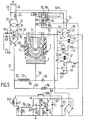
La figure 3 représente une seconde variante de réalisation du système selon l'invention comportant une temporisation variant de manière continue en fonction de la durée de l'étape de coupe précédente. Le circuit représenté sur cette figure 3 est semblable à celui de la figure 2, à l'exception d'une part, des contacts de l'enroulement 142, et d'autre part, du circuit 179 permettant la variation de la temporisation.FIG. 3 represents a second variant embodiment of the system according to the invention comprising a time delay varying continuously as a function of the duration of the preceding cutting step. The circuit represented in this FIG. 3 is similar to that of FIG. 2, except on the one hand, of the contacts of the winding 142, and on the other hand, of the
Le contact temporisé 85 de la figure 2 a été remplacé par un contact simple 85 ainsi qu'un second contact 185 en parallèle sur 85. Ce contact 185 est commandé, ainsi qu'on le verra par la suite, par l'enroulement 242.The timed contact 85 in FIG. 2 has been replaced by a single contact 85 and a
Aux bornes du secondaire 33 du transformateur 31, est connecté le circuit 179, sur les connexions d'entrée d'un pont redresseur P dont les sorties négative et positive sont reliées d'une part aux bornes d'un condensateur C1 et d'autre part à la résistance R1 en série avec la diode Zéner Z1. Aux bornes de la diode Z1, délivrant une tension stabilisée V de valeur égale à sa tension Zéner, est connectée la première extrémité du contact 143 dont l'autre extrémité est reliée à la résistance R2, connectée en série avec le condensateur C2 dont l'armature négative est reliée à la masse. Aux bornes de cette diode Z1 est également connecté un pont diviseur R4-R5 dont le point milieu (à la tention Vc) est relié à l'entrée négative d'un amplificateur comparateur A1, dont l'entrée positive est reliée au point commun à la résistance R2 et au condensateur C2 (à la tension VA), ce point commun étant également connecté à la masse par l'intermédiaire de la résistance R3 afin de permettre (lorsque cela est nécessaire) la décharge du condensateur C2. L'amplificateur comparateur A1 est alimenté à la tension V, tandis que la sortie de A1 (à la tension Vs) est reliée par l'intermédiaire d'une résistance R6 à la base d'un transistor T1 dont l'émetteur est relié à la masse (pole négatif du pont redresseur P). La base de T1 est également mise à la masse par l'intermédiaire de la résistance R7. Le collecteur de T1 est polarisé par l'intermédiaire de l'enroulement 242, qui commande l'ouverture ou la fermeture du contact 185, une diode D1 étant connectée en parallèle sur l'enroulement 242, dans le sens conducteur du collecteur vers l'alimentation positive choisie au point commun de R1 et C1.At the terminals of the secondary 33 of the
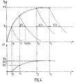
Le fonctionnement du dispositif illustré sur la figure 3 sera mieux compris à l'aide de la figure 4 qui représente, sur la courbe située dans la partie haute de la figure, la variation de la tension VA en fonction du temps t, et sur la courbe située dans la partie basse de la figure, la durée A t de la temporisation, en fonction de la durée t de la coupe.The operation of the device illustrated in Figure 3 will be better understood using Figure 4 which shows, on the curve located in the part top of the figure, the variation of the voltage VA as a function of time t, and on the curve located in the lower part of the figure, the duration A t of the time delay, as a function of the duration t of the cut.
La mise en route du circuit de coupe est identique à celle décrite sur la figure 2. Lorsque l'enroulement 142 est excité, le contact 85 se ferme ce qui engendre un «fort debit» de gaz pendant la période de coupe. Jusqu'à l'instant to, la tension sur l'entrée négative de l'amplificateur comparateur A1 étant supérieure à celle présente sur l'entrée positive, le transistor T1 est bloqué et l'enroulement 242 n'est pas excité. L'interrupteur 185 est ouvert. Lorsque l'on arrête l'opération de coupe, le contact 85 s'ouvre également ce qui se traduit par une désexcitation de l'enroulement 84, la vanne V2 passant immédiatement en position de «faible débit».The start-up of the cutting circuit is identical to that described in FIG. 2. When the winding 142 is energized, the contact 85 closes, which generates a “high flow rate” of gas during the cutting period. Until time t o , the voltage on the negative input of the comparator amplifier A1 being greater than that on the positive input, the transistor T1 is blocked and the winding 242 is not energized.
Lorsque la durée de l'opération de coupe est suffisament longue pour devenir supérieur à to, la tension VA sur l'entrée positive de l'amplificateur comparateur A1 devient supérieure à la tension fixée par le pont diviseur R4, R5 sur l'entrée négative de A1. Ceci entraine une tension positive sur la base du transistor T1 qui devient conducteur: l'enroulement 242 est excité ce qui entraine la fermeture du contact 185. Si l'opération de coupe est arrêtée à l'instant t1, l'enroulement 142 est désexcité et le contact 85 s'ouvre. Le contact 143, dont la fermeture a été commandée par l'excitation de l'enroulement 48 (voir description figure 2), s'ouvre ce qui entraine la décharge du condensateur C2 via la résistance R3. Après l'intervalle de temps A t1, la tension aux bornes du condensateur C2 redevient égale à Vc, et l'enroulement 242 est désexcité, ce qui engendre alors l'ouverture du contact 185 et la désexcitation de l'enroulement 84: la vanne V2, en position de «fort débit» lorsque l'enroulement 84 est excité, passe alors en position de «faible débit».When the duration of the cutting operation is long enough to become greater than t 0 , the voltage VA on the positive input of the comparator amplifier A1 becomes greater than the voltage fixed by the divider bridge R4, R5 on the input negative of A 1 . This causes a positive voltage on the base of the transistor T1 which becomes conductive: the winding 242 is excited which causes the closure of the
La figure 4 montre en outre que si l'on cesse l'opération de coupe aux instants t2 ou t3, ..., on obtiendra une temporisation A t de durée A t2, A t3, ... Lorsque la durée de l'opération de coupe est telle que le condensateur est complètement chargé (tension V entre les armatures), la durée A t de la temporisation devient sensiblement constante (A t2 sensiblement égal à A t3).FIG. 4 also shows that if one stops the cutting operation at times t 2 or t 3 , ..., one will obtain a time delay A t of duration A t 2 , A t 3 , ... When the duration of the cutting operation is such that the capacitor is fully charged (voltage V between the plates), the duration A t of the time delay becomes substantially constant (A t 2 substantially equal to A t 3 ).
La figure 5 représente une troisième variante de réalisation du système selon l'invention comportant une temporisation à double durée. Lorsque la durée de l'opération de coupe à été inférieure à une valeur prédéterminée, la temporisation à une faible durée de valeur prédéterminée, eventuellement réglable. Cette faible durée est généralement nulle. Lorsque la durée de l'étape coupe est supérieure à cette valeur prédéterminée (coupe de longue durée), la temporisation prend une seconde valeur prédéterminée, eventuellement réglable, plus longue que la précédente. En pratique, toutefois, la durée de la plus longue des temporisations n'excède pas généralement quelques secondes.FIG. 5 represents a third alternative embodiment of the system according to the invention comprising a double duration time delay. When the duration of the cutting operation has been less than a predetermined value, the time delay at a low duration of predetermined value, possibly adjustable. This short duration is generally zero. When the duration of the cutting step is greater than this predetermined value (long duration cutting), the time delay takes a second predetermined value, possibly adjustable, longer than the previous one. In practice, however, the duration of the longest time delay does not generally exceed a few seconds.
Le circuit représenté sur la figure 5 est sensiblement identique à celui représenté sur la figure 4 avec toutefois les différences suivantes: le contact 185 à été remplacé par un contact temporisé 385, en parallèle sur le contact 185, tandis que l'alimentation du collecteur T1 via l'enroulement 242 se fait par l'intermédiaire d'un contact 285 dont la fermeture et l'ouverture sont commandées par l'excitation et la désexcitation de l'enroulement 142, qui commande également la fermeture et l'ouverture du contact 85.The circuit represented in FIG. 5 is substantially identical to that represented in FIG. 4 with the following differences: the
Le fonctionnement du circuit représenté sur la figure 5 est le suivant: à l'instant to, lorsque débute l'opération de coupe, l'enroulement 142 est excité et le contact 85 se ferme, ce qui entraîne le passage du gaz à fort débit dans V2. Si l'on arrête la coupe avant l'instant t, (voir figure 4) l'enroulement 242 n'est pas excité et le contact 385 reste ouvert. Comme l'arrêt de la coupe entraîne l'ouverture du contact 85, le fort débit de gaz est également arrêté et la vanne V2 est traversée par le «faible débit» de gaz. Il n'y a donc pas de temporisation dans le cas présent.The operation of the circuit shown in Figure 5 is as follows: at time t o , when the cutting operation begins, the winding 142 is energized and the contact 85 closes, which causes the passage of gas at high flow in V 2 . If the cut is stopped before time t (see Figure 4) the winding 242 is not energized and the contact 385 remains open. As the cutting stop opens the contact 85, the high gas flow is also stopped and the valve V 2 is crossed by the "low flow" of gas. There is therefore no time delay in the present case.
Par contre, si l'opération de coupe est arrêtée au delà de l'instant t1, il en est tout différemment. A partir de l'instant ti, le comparateur A1 bascule et l'enroulement 242 est excité, puisque le contact 285 s'est fermé à l'instant to lorsque l'enroulement 142 a été excité. Si l'on arrête la coupe à l'instant t3, par exemple (figure 4) l'enroulement 142 est désexcité, ce qui entraîne d'une part, l'ouverture du contact 85 et d'autre part l'ouverture du contact 285. L'ouverture de ce dernier entraîne la désexcitation de l'enroulement 242 qui engendre l'ouverture temporisée du contact 385. On maintient ainsi un «fort débit» de gaz dans la vanne V2 et dans la tuyère après la fin de l'étape de coupe, la durée de ce «fort débit» étant égale à la valeur de la temporisation de l'interupteur temporisé 385. Comme précédemment, cette valeur n'excède pas, généralement, quelques secondes.On the other hand, if the cutting operation is stopped beyond time t 1 , it is quite different. From the instant t i , the comparator A1 switches and the winding 242 is energized, since the
Bien entendu, l'homme de métier peut, sans sortir du cadre de l'invention, réaliser les variantes des figures 3 et 5, de diverses manières en utilisant par exemple des circuits logiques (portes logiques, compteurs, etc...) travaillant avec des signaux numériques déclenchés par le début et la fin des opérations de coupe, ou des relais temporisés (en particulier pour la variante de la figure 5). On peut en particulier, en utilisant des circuits logiques numériques, modifier la courbe A t = f (t) (exemple: fig. 4) de manière à lui donner la forme voulue, selon une fonction linéaire, polynômiale. etc... Le but de la temporisation variable est de fournir une durée de refroidissement qui soit directement fonction de la température de la torche après l'opération de coupe précédente. Pour cela. on peut relever expérimentalement la courbe d'échauffement de la torche (en un point déterminé de celle-ci, par exemple à proximité de l'électrode) en fonction de la durée de coupe et reproduire sensiblement la même courbe pour la temporisation variable.Of course, the skilled person can, without departing from the scope of the invention, produce the variants of Figures 3 and 5, in various ways using for example logic circuits (logic gates, counters, etc.) working with digital signals triggered by the start and end of cutting operations, or timed relays (in particular for the variant in Figure 5). One can in particular, using digital logic circuits, modify the curve A t = f (t) (example: fig. 4) so as to give it the desired shape, according to a linear, polynomial function. etc ... The purpose of the variable time delay is to provide a cooling time which is directly a function of the temperature of the torch after the previous cutting operation. For that. it is possible to record experimentally the heating curve of the torch (at a determined point thereof, for example near the electrode) as a function of the cutting time and to reproduce substantially the same curve for the variable time delay.
Bien qu'il soit possible d'utiliser deux gaz différents pour engendrer les deux débits différents. avec deux circuits d'alimentation séparés, arrivant sur l'électrovanne V2, chaque circuit étant commandé en synchronisation avec la commutation de la vanne du premier au second débit et vice-versa, il sera généralement plus simple d'utiliser le même gaz pour les deux débits.Although it is possible to use two different gases to generate two different flow rates. with two separate supply circuits, arriving at the solenoid valve V 2 , each circuit being com ordered in synchronization with the switching of the valve from the first to the second flow and vice versa, it will generally be easier to use the same gas for the two flows.
Claims (9)
Priority Applications (1)
| Application Number | Priority Date | Filing Date | Title |
|---|---|---|---|
| AT86400343T ATE46804T1 (en) | 1985-02-22 | 1986-02-19 | PLASMA CUTTING OR PLASMA WELDING SYSTEM WITH TIMER. |
Applications Claiming Priority (2)
| Application Number | Priority Date | Filing Date | Title |
|---|---|---|---|
| FR8502554 | 1985-02-22 | ||
| FR8502554A FR2578138B1 (en) | 1985-02-22 | 1985-02-22 | PLASMA WELDING OR CUTTING SYSTEM WITH TIMING |
Publications (2)
| Publication Number | Publication Date |
|---|---|
| EP0192573A1 EP0192573A1 (en) | 1986-08-27 |
| EP0192573B1 true EP0192573B1 (en) | 1989-09-27 |
Family
ID=9316525
Family Applications (1)
| Application Number | Title | Priority Date | Filing Date |
|---|---|---|---|
| EP86400343A Expired EP0192573B1 (en) | 1985-02-22 | 1986-02-19 | System for plasma cutting or welding incorporating a timer |
Country Status (14)
| Country | Link |
|---|---|
| US (1) | US4692582A (en) |
| EP (1) | EP0192573B1 (en) |
| JP (1) | JPS61222678A (en) |
| AR (1) | AR240119A1 (en) |
| AT (1) | ATE46804T1 (en) |
| AU (1) | AU577673B2 (en) |
| BR (1) | BR8600731A (en) |
| CA (1) | CA1253578A (en) |
| DE (1) | DE3665970D1 (en) |
| DK (1) | DK169455B1 (en) |
| ES (1) | ES8705181A1 (en) |
| FR (1) | FR2578138B1 (en) |
| PT (1) | PT82065B (en) |
| ZA (1) | ZA861214B (en) |
Families Citing this family (25)
| Publication number | Priority date | Publication date | Assignee | Title |
|---|---|---|---|---|
| CA1310706C (en) * | 1988-04-26 | 1992-11-24 | Toshihiko Okada | Water cooled plasma arc apparatus |
| US5166494A (en) * | 1990-04-24 | 1992-11-24 | Hypertherm, Inc. | Process and apparatus for reducing electrode wear in a plasma arc torch |
| US5396043A (en) * | 1988-06-07 | 1995-03-07 | Hypertherm, Inc. | Plasma arc cutting process and apparatus using an oxygen-rich gas shield |
| US5695662A (en) * | 1988-06-07 | 1997-12-09 | Hypertherm, Inc. | Plasma arc cutting process and apparatus using an oxygen-rich gas shield |
| US5070227A (en) * | 1990-04-24 | 1991-12-03 | Hypertherm, Inc. | Proceses and apparatus for reducing electrode wear in a plasma arc torch |
| DE3840459A1 (en) * | 1988-11-14 | 1990-05-17 | Merkle Wilhelm Schweissmasch | Cutting torch |
| IT1225341B (en) * | 1988-11-15 | 1990-11-13 | Cebora Spa | PROTECTION CIRCUIT FOR A PLASMA WELDING OR CUTTING EQUIPMENT WITH NON-TRANSFERRED OR TRANSFERRED ARC |
| US4973816A (en) * | 1989-03-28 | 1990-11-27 | Delaware Capital Formation, Inc. | Plasma torch with safety switch |
| US4996407A (en) * | 1989-04-03 | 1991-02-26 | Hyperpower, Inc. | Plasma arc transfer controller |
| US5216221A (en) * | 1992-01-17 | 1993-06-01 | Esab Welding Products, Inc. | Plasma arc torch power disabling mechanism |
| US5416297A (en) * | 1993-03-30 | 1995-05-16 | Hypertherm, Inc. | Plasma arc torch ignition circuit and method |
| US5620617A (en) * | 1995-10-30 | 1997-04-15 | Hypertherm, Inc. | Circuitry and method for maintaining a plasma arc during operation of a plasma arc torch system |
| US5961855A (en) * | 1998-01-28 | 1999-10-05 | Thermal Dynamics Corporation | Low voltage electrical based parts-in-place (PIP) system for contact start torch |
| US6677551B2 (en) * | 1998-10-23 | 2004-01-13 | Innerlogic, Inc. | Process for operating a plasma arc torch |
| US6326583B1 (en) | 2000-03-31 | 2001-12-04 | Innerlogic, Inc. | Gas control system for a plasma arc torch |
| US6498317B2 (en) | 1998-10-23 | 2002-12-24 | Innerlogic, Inc. | Process for operating a plasma arc torch |
| US6163009A (en) * | 1998-10-23 | 2000-12-19 | Innerlogic, Inc. | Process for operating a plasma arc torch |
| DE29911974U1 (en) * | 1999-07-09 | 2000-11-23 | Agrodyn Hochspannungstechnik GmbH, 33803 Steinhagen | Plasma nozzle |
| US6350960B1 (en) | 2000-11-28 | 2002-02-26 | Thermal Dynamics Corporation | Parts-in-place safety reset circuit and method for contact start plasma-arc torch |
| US7807937B2 (en) * | 2005-01-03 | 2010-10-05 | Illinois Tool Works Inc. | Method and system of conserving plasma torch consumable |
| US20080055795A1 (en) * | 2006-08-25 | 2008-03-06 | Miller Theodore J | Power supply start-up circuit for a trip unit and circuit interrupter including the same |
| US8258423B2 (en) * | 2009-08-10 | 2012-09-04 | The Esab Group, Inc. | Retract start plasma torch with reversible coolant flow |
| US9949356B2 (en) | 2012-07-11 | 2018-04-17 | Lincoln Global, Inc. | Electrode for a plasma arc cutting torch |
| EP3490749B1 (en) * | 2016-07-29 | 2020-10-21 | Illinois Tool Works Inc. | Automated plasma cutting apparatus with a housing comprising a movable plasma nozzle, and plasma cutting system |
| CN112655280B (en) * | 2018-08-28 | 2023-10-20 | 株式会社富士 | Plasma generating device and plasma head cooling method |
Family Cites Families (7)
| Publication number | Priority date | Publication date | Assignee | Title |
|---|---|---|---|---|
| US3242305A (en) * | 1963-07-03 | 1966-03-22 | Union Carbide Corp | Pressure retract arc torch |
| US3433927A (en) * | 1964-05-21 | 1969-03-18 | Union Carbide Corp | Method for establishing and closing an arc weld |
| US4122327A (en) * | 1975-07-17 | 1978-10-24 | Metco Inc. | Automatic plasma flame spraying process and apparatus |
| GB1572847A (en) * | 1977-03-18 | 1980-08-06 | Rolls Royce | Plasma arc welding |
| JPS5768270A (en) * | 1980-10-17 | 1982-04-26 | Hitachi Ltd | Control method for plasma cutting |
| FR2562453B1 (en) * | 1984-04-04 | 1988-02-26 | Soudure Autogene Francaise | VERY LOW POWER PLASMA CUTTING EQUIPMENT |
| US4580032A (en) * | 1984-12-27 | 1986-04-01 | Union Carbide Corporation | Plasma torch safety device |
-
1985
- 1985-02-22 FR FR8502554A patent/FR2578138B1/en not_active Expired
-
1986
- 1986-02-17 ES ES552069A patent/ES8705181A1/en not_active Expired
- 1986-02-18 ZA ZA861214A patent/ZA861214B/en unknown
- 1986-02-18 US US06/830,112 patent/US4692582A/en not_active Expired - Fee Related
- 1986-02-19 EP EP86400343A patent/EP0192573B1/en not_active Expired
- 1986-02-19 DE DE8686400343T patent/DE3665970D1/en not_active Expired
- 1986-02-19 AT AT86400343T patent/ATE46804T1/en not_active IP Right Cessation
- 1986-02-20 DK DK078386A patent/DK169455B1/en not_active IP Right Cessation
- 1986-02-20 AU AU53783/86A patent/AU577673B2/en not_active Ceased
- 1986-02-21 BR BR8600731A patent/BR8600731A/en not_active IP Right Cessation
- 1986-02-21 AR AR303203A patent/AR240119A1/en active
- 1986-02-21 PT PT82065A patent/PT82065B/en not_active IP Right Cessation
- 1986-02-22 JP JP61038139A patent/JPS61222678A/en active Granted
- 1986-02-24 CA CA000502508A patent/CA1253578A/en not_active Expired
Also Published As
| Publication number | Publication date |
|---|---|
| JPS61222678A (en) | 1986-10-03 |
| CA1253578A (en) | 1989-05-02 |
| US4692582A (en) | 1987-09-08 |
| AR240119A1 (en) | 1990-01-31 |
| ATE46804T1 (en) | 1989-10-15 |
| FR2578138B1 (en) | 1987-03-27 |
| DE3665970D1 (en) | 1989-11-02 |
| DK169455B1 (en) | 1994-10-31 |
| JPH029917B2 (en) | 1990-03-05 |
| PT82065B (en) | 1992-05-29 |
| FR2578138A1 (en) | 1986-08-29 |
| ZA861214B (en) | 1986-10-29 |
| DK78386A (en) | 1986-08-23 |
| BR8600731A (en) | 1986-11-04 |
| AU5378386A (en) | 1986-08-28 |
| ES552069A0 (en) | 1987-04-16 |
| ES8705181A1 (en) | 1987-04-16 |
| DK78386D0 (en) | 1986-02-20 |
| PT82065A (en) | 1986-03-01 |
| EP0192573A1 (en) | 1986-08-27 |
| AU577673B2 (en) | 1988-09-29 |
Similar Documents
| Publication | Publication Date | Title |
|---|---|---|
| EP0192573B1 (en) | System for plasma cutting or welding incorporating a timer | |
| EP3459100B1 (en) | Breaker device intended to be linked to an electrical circuit | |
| EP0159256B1 (en) | Very low power plasma-cutting equipment | |
| FR2666261A1 (en) | SYSTEM AND METHOD FOR SHORT-CIRCUIT ARC WELDING. | |
| EP0066481A1 (en) | Electronic supply apparatus for discharge lamps | |
| FR2496384A1 (en) | STARTER FOR PRIMING A DISCHARGE TUBE IN A GAS AND / OR A STEAM, AND AN ELECTRIC DEVICE AND LAMP HAVING A STARTER OF THIS TYPE | |
| FR2636169A1 (en) | STARTING MEANS, WITH PIEZOELECTRICALLY PLACED CAPACITIVE CAPACITIVE ELECTRODES FOR HIGH INTENSITY DISCHARGE LAMPS | |
| EP3288059B1 (en) | Commandable trip unit for an electrical circuit breaker | |
| FR2538942A1 (en) | Device for control of electromagnetic unit(s) with rapid action, such as electrovalve(s) or injector(s) | |
| FR2480909A1 (en) | FLAME IGNITION AND DETECTION DEVICE | |
| FR2648001A1 (en) | Direct current supply for plasma electrodes and process for regenerating a plasma | |
| FR2646538A1 (en) | Motor vehicle lighting device including means of protection against short-circuits | |
| FR2470467A1 (en) | APPARATUS FOR RECHARGING BATTERIES OR BATTERIES BY A PULSE CURRENT | |
| EP0439417B1 (en) | Safety device for the operating of a burner | |
| FR2583856A1 (en) | TEMPORIZED CUTTING CIRCUIT OF A GAS BURNER | |
| FR3099289A1 (en) | Contactor and method of controlling a contactor | |
| FR2751730A1 (en) | POSITIVE SECURING DEVICE FOR ADMISSION OF GAS INTO A BURNER | |
| FR2490129A1 (en) | METHOD AND INSTALLATION FOR CONTROLLING THE CONTACT BETWEEN RESISTANCE WELDING ELECTRODES AND A WORKPIECE TO BE WELDED, AND THE TIGHTENING OF SAID ELECTRODES ON THE WORKPIECE | |
| EP1066910A1 (en) | Arc welding power supply with alternating arc and short circuit periods | |
| FR2495823A1 (en) | Automatic AC supply switch with random delay - has relay controlling two inverter contacts in supply lines of which solenoid has diode exciter circuit and series resistor across lines and | |
| FR2653276A1 (en) | Electronic switch with series DC power supply | |
| BE447794A (en) | ||
| BE542313A (en) | ||
| BE502285A (en) | ||
| FR2478931A1 (en) | DEVICE PROVIDED WITH A CONTACT-FREE AND HIGH-FREQUENCY ELECTRIC ARC FORMING MECHANISM |
Legal Events
| Date | Code | Title | Description |
|---|---|---|---|
| PUAI | Public reference made under article 153(3) epc to a published international application that has entered the european phase |
Free format text: ORIGINAL CODE: 0009012 |
|
| 17P | Request for examination filed |
Effective date: 19860224 |
|
| AK | Designated contracting states |
Kind code of ref document: A1 Designated state(s): AT BE CH DE FR GB IT LI LU NL SE |
|
| 17Q | First examination report despatched |
Effective date: 19880321 |
|
| GRAA | (expected) grant |
Free format text: ORIGINAL CODE: 0009210 |
|
| AK | Designated contracting states |
Kind code of ref document: B1 Designated state(s): AT BE CH DE FR GB IT LI LU NL SE |
|
| REF | Corresponds to: |
Ref document number: 46804 Country of ref document: AT Date of ref document: 19891015 Kind code of ref document: T |
|
| ITF | It: translation for a ep patent filed | ||
| GBT | Gb: translation of ep patent filed (gb section 77(6)(a)/1977) | ||
| REF | Corresponds to: |
Ref document number: 3665970 Country of ref document: DE Date of ref document: 19891102 |
|
| PLBE | No opposition filed within time limit |
Free format text: ORIGINAL CODE: 0009261 |
|
| STAA | Information on the status of an ep patent application or granted ep patent |
Free format text: STATUS: NO OPPOSITION FILED WITHIN TIME LIMIT |
|
| 26N | No opposition filed | ||
| ITTA | It: last paid annual fee | ||
| EPTA | Lu: last paid annual fee | ||
| EAL | Se: european patent in force in sweden |
Ref document number: 86400343.9 |
|
| PGFP | Annual fee paid to national office [announced via postgrant information from national office to epo] |
Ref country code: FR Payment date: 19980112 Year of fee payment: 13 |
|
| PGFP | Annual fee paid to national office [announced via postgrant information from national office to epo] |
Ref country code: AT Payment date: 19980115 Year of fee payment: 13 |
|
| PGFP | Annual fee paid to national office [announced via postgrant information from national office to epo] |
Ref country code: SE Payment date: 19980116 Year of fee payment: 13 |
|
| PGFP | Annual fee paid to national office [announced via postgrant information from national office to epo] |
Ref country code: GB Payment date: 19980121 Year of fee payment: 13 |
|
| PGFP | Annual fee paid to national office [announced via postgrant information from national office to epo] |
Ref country code: DE Payment date: 19980126 Year of fee payment: 13 |
|
| PGFP | Annual fee paid to national office [announced via postgrant information from national office to epo] |
Ref country code: NL Payment date: 19980127 Year of fee payment: 13 Ref country code: CH Payment date: 19980127 Year of fee payment: 13 |
|
| PGFP | Annual fee paid to national office [announced via postgrant information from national office to epo] |
Ref country code: LU Payment date: 19980203 Year of fee payment: 13 |
|
| PGFP | Annual fee paid to national office [announced via postgrant information from national office to epo] |
Ref country code: BE Payment date: 19980205 Year of fee payment: 13 |
|
| PG25 | Lapsed in a contracting state [announced via postgrant information from national office to epo] |
Ref country code: LU Free format text: LAPSE BECAUSE OF NON-PAYMENT OF DUE FEES Effective date: 19990219 Ref country code: GB Free format text: LAPSE BECAUSE OF NON-PAYMENT OF DUE FEES Effective date: 19990219 Ref country code: AT Free format text: LAPSE BECAUSE OF NON-PAYMENT OF DUE FEES Effective date: 19990219 |
|
| PG25 | Lapsed in a contracting state [announced via postgrant information from national office to epo] |
Ref country code: SE Free format text: LAPSE BECAUSE OF NON-PAYMENT OF DUE FEES Effective date: 19990220 |
|
| PG25 | Lapsed in a contracting state [announced via postgrant information from national office to epo] |
Ref country code: LI Free format text: LAPSE BECAUSE OF NON-PAYMENT OF DUE FEES Effective date: 19990228 Ref country code: CH Free format text: LAPSE BECAUSE OF NON-PAYMENT OF DUE FEES Effective date: 19990228 Ref country code: BE Free format text: LAPSE BECAUSE OF NON-PAYMENT OF DUE FEES Effective date: 19990228 |
|
| BERE | Be: lapsed |
Owner name: L' AIR LIQUIDE S.A. POUR L'ETUDE ET L'EXPLOITATION Effective date: 19990228 Owner name: LA SOUDURE AUTOGENE FRANCAISE Effective date: 19990228 |
|
| PG25 | Lapsed in a contracting state [announced via postgrant information from national office to epo] |
Ref country code: NL Free format text: LAPSE BECAUSE OF NON-PAYMENT OF DUE FEES Effective date: 19990901 |
|
| GBPC | Gb: european patent ceased through non-payment of renewal fee |
Effective date: 19990219 |
|
| REG | Reference to a national code |
Ref country code: CH Ref legal event code: PL |
|
| PG25 | Lapsed in a contracting state [announced via postgrant information from national office to epo] |
Ref country code: FR Free format text: LAPSE BECAUSE OF NON-PAYMENT OF DUE FEES Effective date: 19991029 |
|
| EUG | Se: european patent has lapsed |
Ref document number: 86400343.9 |
|
| PG25 | Lapsed in a contracting state [announced via postgrant information from national office to epo] |
Ref country code: DE Free format text: LAPSE BECAUSE OF NON-PAYMENT OF DUE FEES Effective date: 19991201 |
|
| REG | Reference to a national code |
Ref country code: FR Ref legal event code: ST |
|
| PG25 | Lapsed in a contracting state [announced via postgrant information from national office to epo] |
Ref country code: IT Free format text: LAPSE BECAUSE OF NON-PAYMENT OF DUE FEES Effective date: 20050219 |