EP0192497B1 - Apparatus to compress the dynamic range of the three colour signals constituting a picture - Google Patents
Apparatus to compress the dynamic range of the three colour signals constituting a picture Download PDFInfo
- Publication number
- EP0192497B1 EP0192497B1 EP86400008A EP86400008A EP0192497B1 EP 0192497 B1 EP0192497 B1 EP 0192497B1 EP 86400008 A EP86400008 A EP 86400008A EP 86400008 A EP86400008 A EP 86400008A EP 0192497 B1 EP0192497 B1 EP 0192497B1
- Authority
- EP
- European Patent Office
- Prior art keywords
- value
- signal
- signals
- dynamic range
- colour
- Prior art date
- Legal status (The legal status is an assumption and is not a legal conclusion. Google has not performed a legal analysis and makes no representation as to the accuracy of the status listed.)
- Expired - Lifetime
Links
Images


Classifications
-
- H—ELECTRICITY
- H04—ELECTRIC COMMUNICATION TECHNIQUE
- H04N—PICTORIAL COMMUNICATION, e.g. TELEVISION
- H04N9/00—Details of colour television systems
- H04N9/64—Circuits for processing colour signals
- H04N9/68—Circuits for processing colour signals for controlling the amplitude of colour signals, e.g. automatic chroma control circuits
- H04N9/69—Circuits for processing colour signals for controlling the amplitude of colour signals, e.g. automatic chroma control circuits for modifying the colour signals by gamma correction
-
- H—ELECTRICITY
- H04—ELECTRIC COMMUNICATION TECHNIQUE
- H04N—PICTORIAL COMMUNICATION, e.g. TELEVISION
- H04N9/00—Details of colour television systems
- H04N9/64—Circuits for processing colour signals
- H04N9/68—Circuits for processing colour signals for controlling the amplitude of colour signals, e.g. automatic chroma control circuits
Definitions
- the invention relates to a device for reducing the dynamic range of three color signals representing an image, these three signals being supplied by any source: camera, telecine, etc. These signals have a dynamic range greater than that which is acceptable by the means of transmission or recording commonly used. To restore a correct image it is necessary to reduce the dynamics of these signals before their transmission or recording so that their values never exceed a fixed maximum value. Since the values of very high amplitude are statistically few in number, they are sacrificed in favor of the average values and the low values which make it possible to reconstruct the essential information of the image. In order not to completely lose the information corresponding to the peaks of these signals, these are not clipped but only compressed.
- the three color signals represent picture elements that are achromatic
- the three color signals have the same value. Consequently, the signals reproduced by the three quadrupoles have the same value and the elements of the reconstructed image remain colorless.
- the color signals corresponding to colored elements do not have the same value and their differences in value are reduced when these values are sufficiently high for the quadrupoles to achieve compression.
- the values of these three signals then tend to become equal at the output of the quadrupoles, and the restored picture elements therefore tend to become achromatic. This phenomenon is all the more sensitive as the colors are less saturated: skin tone, blue sky, pastel shade, etc.
- the invention relates to a device for reducing the dynamics of the three color signals representing an image, which does not have this drawback.
- the diagram shown in Figure 1 corresponds to a device of the prior art; it includes three identical non-linear quadrupoles, 4 to 6, receiving three color signals respectively on three input terminals 1 to 3, and respectively rendering three color signals whose dynamics are reduced, on three output terminals 7 to 9
- the three color signals whose dynamics are to be reduced have the instantaneous value Ve l , Ve 2 and Ve 3 respectively .
- the three color signals whose dynamics have been reduced respectively have the values, at the same instant, V S1 , Vs 2 , Vs o .
- the values of the restored signals are linked to the values of the signals applied to the input terminals by the relations:
- the ratio k between the value of the input signal and the value of the signal at the output of each quadrupole depends on the value of the signal at the input. k is equal to 1 when the value of the input signal is less than a fixed value which is identical for the three quadrupoles, and is less than 1 for the values of the input signal which are greater than the value of this threshold . Since the values of the three input signals are not identical, the values of k at a given time are generally different. When all the input signals have a value lower than the threshold value, the value of k is equal to 1 for all the signals, the ratios between the values of the signals at the input are preserved, consequently the colors of the elements corresponding images are retained.
- FIG. 2 represents the block diagram of a more improved device according to the prior art.
- This example includes three analog multipliers, 14 to 16; and a device 20 for determining a correction coefficient c (Vm).
- Three color signals whose dynamics are to be reduced are applied respectively to three input terminals, 11 to 13, and have the value respectively: Ve l , Ve 2 and Ve 3 . They are transmitted respectively to the first inputs of the multipliers 14 to 16 and to three inputs of the device 20.
- the device 20 provides a signal of value c (Vm) on an output terminal 10 which is connected to second inputs of the multipliers 14 to 16.
- the multipliers 14 to 16 have outputs connected respectively to three output terminals, 17 to 19, of the device according to the invention. These output terminals respectively provide three color signals whose dynamics are reduced and whose values are:
- This device therefore achieves the multiplication of each of the three color signals by the same correction coefficient value c (Vm).
- This coefficient is a function of the value Vm which is the largest value, at an instant considered, among the three values of the color signals.
- Vm is less than a fixed threshold
- the value c (Vm) is equal to 1
- the value c (Vm) is less than 1 to obtain compression.
- the values of the three color signals being multiplied by the same value, their ratios are therefore preserved and the colors of the corresponding picture elements are not altered.
- FIG. 3 represents a more detailed block diagram of the device 20 for determining a correction coefficient c (Vm). It comprises: a device 45 for determining the highest value; a non-linear quadrupole 46; and an analog divider 47.
- the three inputs of the device 20 are connected to three inputs of the device 45 and the latter has an output connected to an input of the quadrupole 46 and to a first input of the divider 47.
- a second input of the divider 47 is connected to an output of the quadrupole 46 and an output of the divider 47 constitutes the output of the device 20 and is connected to the output terminal 10.
- the output of the device 45 for determining the largest value provides a signal of value Vm at the input of the quadrupole 46.
- the latter performs a unity gain transmission, or compression, and restores a signal of value f (Vm) .
- Divider 47 provides a value signal which makes it possible to control the compression operation of all three color signals, as a function of the compression to be obtained on the color signal which, at the instant considered, most needs to be compressed.
- the device 45 can be constituted by a combination of three diodes coupled by their cathodes.
- the three color signals are applied to the three anodes respectively.
- the diode with the most positive anode is the only one that leads.
- the non-linear quadrupole 46 has a transfer function, the graph of which consists of two straight segments: a first segment having a unit slope and corresponding to the low and medium values, and a second segment with a slope less than 1 and corresponding to the values high.
- FIG. 4 represents the block diagram of another known device which comprises the same elements as the previous device but the device 20 ′ for determining a correction coefficient has its three inputs connected not to the input terminals, 11 ′ at 13 ', but at the output terminals, 17' at 19 '.
- the determination of the color signal having the largest instantaneous value is unchanged and the value c '(Vm) of the correction signal converges to a value little different from c (Vm).
- the effect of compression is therefore very similar. It is an embodiment of this type which is described in the aforementioned US patent.
- FIG. 5 represents the block diagram of the device according to the invention.
- the three color signals are processed not by multipliers but by subtractors and the value of each of the restored color signals is calculated by a linear function of the value of the color signal considered and of the value h (Vm ) a correction signal.
- These subtractors receive three correction signals which are distinct and which are different from the correction signal f (Vm) generated by the devices 20 and 20 ′ of the previous devices; the values Vs i , Vs 2 , Vs 3 of the output signals are still linked to the values of the input signals by relations of the form:
- this device comprises: three analog subtractors 34 to 36; three analog multipliers 37 to 39; and a device 40 for determining a correction coefficient.
- the subtractors 34 to 36 have: first inputs connected respectively to three input terminals 31 to 33 of the device according to the invention; second inputs connected respectively to outputs of multipliers 37 to 39; and outputs connected respectively to three output terminals 42 to 44 of the device according to the invention.
- the multipliers 37 to 39 have first inputs connected respectively to the three input terminals 31 to 33 and have second inputs connected to an output terminal 41 of the device 40.
- the device 40 has three inputs connected respectively to the three input terminals 31 to 33.
- the device 40 generates a signal of value h (Vm) which is transmitted by its output terminal 41 to the second inputs of the multipliers 37 to 39. These latter then provide three correction signals respectively having the value:
- Subtractors 34 to 36 therefore provide color signals whose dynamics are reduced, which have respectively the value:
- the values Vc i , Vc 2 , and Vc 3 , of the correction signals are generally lower than the original values Ve l , Ve 2 , and Ve 3 of the color signals.
- the correction signals have a zero value. Therefore, when there is no compression, the correction signals cannot add distortion to the color signals.
- the color signals passing through the subtractors 34 to 36 are less distorted than the color signals passing through multipliers such as those used in the two variants described above, because the analog subtractors are generally more linear than analog multipliers. This device therefore has the advantage of transmitting color signals with less distortion.
- FIG. 6 represents the block diagram of an exemplary embodiment of the device 40 for determining a correction coefficient h (Vm).
- the device 40 comprises: a device 48 for determining the highest value; a non-linear quadrupole 49; and an analog divider 50.
- the device 48 has three inputs respectively connected to the three inputs of the device 40 and an output connected to an input of the quadrupole 49 and to a first input of the divider 50.
- a second input of the divider 50 is connected to an output of the quadrupole 49.
- An output of the divider 50 constitutes the output of the device 40 and is connected to the output terminal 41.
- the device 48 selects the value Vm which is the largest among the values of the three input color signals, and transmits it to the non-linear quadrupole 49.
- the latter restores a value g (Vm) which is a function of the value Vm according to a non-linear law, the graph of which comprises a first segment of zero slope and corresponding to the low and average values of Vm, and a second segment having a negative slope of value a and corresponding to the high values of Vm.
- the value S of the threshold separating the two segments and the slope a of the second segment are adjustable by the user of the device respectively over a range S o , S 2 and over a range a o , a 2 .
- the divider 50 provides a value correction signal
- FIG. 7 represents the graph of the transfer function of the quadrupole 49, in bold lines for a threshold value S and a slope value a, and in dotted lines for threshold values S o with a slope a o and for a threshold value S 2 with a slope value a 2 .
- the threshold value and the associated slope value are chosen such that for a color signal value equal to the maximum possible, Vd, the value of the signal supplied by the quadrupole 49 is equal to a fixed value R and identical in all cases.
- This value R corresponds to the reduction in dynamics which is necessary and which is independent of the adjustments of a and S made by the user.
- the R value of the dynamic reduction is imposed by the characteristics of the source of the color signals and by the characteristics of the system receiving the signals after the dynamic reduction.
- the choice of the threshold and the slope is left to the user of the device according to the invention and it is made according to the visual result obtained.
- FIG. 8 represents the graph of Vm-g (Vm) as a function of Vm, that is to say represents the transmission curve of the device according to the invention for the color signal having the greatest amplitude at the moment considered.
- the bold line graph corresponds to a threshold value S and to the slope of value a for the quadrupole 49.
- the dashed graphs correspond to a threshold value S o and to a slope of value a o , on the one hand, and, on the other hand, at a threshold value S 2 and at a slope value a 2 . In the latter case, the graph comprises a segment of almost zero slope in the area of the high values close to the maximum value Vd.
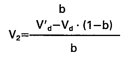
- Vd ' Vd-R which is determined by the characteristics of the transmission or recording systems located downstream of the device according to the invention. There is then practically a clipping of the three color signals.
- non-linear quadrupole 49 the graph of which comprises a segment of zero slope and a segment of non-zero slope is easier than the realization of the non-linear quadrupole 46 of the preceding variants, in particular if it is desired to be able to set the threshold and slope value.
- FIG. 9 represents the more detailed block diagram of the device 40 for determining a correction coefficient represented in FIG. 6. This exemplary embodiment is represented in a more detailed manner than in FIG. 6 and it allows the adjustment of the threshold S and slope a by a single command.
- FIG. 9 represents the block diagram of an exemplary embodiment of the divider 50.
- the device 40 comprises a device 48 for determining the largest value Vm among the values of the color signals whose dynamics are to be reduced, an analog divider 50, and a non-linear quadrupole 49.
- the latter consists of: three subtractors analogs 51, 52, and 54; an analog multiplier 53; two generators 57 and 56 of fixed voltage V, and V 2 ; a generator 58 of adjustable voltage K; and in non-linear quadrupole with fixed characteristic 55.
- the input of the quadrupole 49 is connected to first inputs of the subtractors 51 and 52.
- a second input of the subtractor 51 is connected to the generator 56 of voltage V 2 .
- a second input of the subtractor 52 is connected to the generator 57 of voltage V i .
- An output of the subtractor 51 is connected to a first input of the subtractor 54.
- An output of the subtractor 52 is connected to a first input of the multiplier 53.
- a second input of the multiplier 53 is connected to the generator 58 of voltage K and an output of the multiplier 53 is connected to a second input of the subtractor 54.
- An output of the subtractor 54 is connected to an input of the quadrupole 55 and an output of the latter constitutes the output of the quadrupole 49 and is connected to an input of the divider 50.
- the transfer function of the quadrupole 55 comprises a first segment, of zero slope, for the negative values of its input signal, and a second segment of positive and fixed slope b, for the positive values of its input signal.
- the divider 50 consists of an operational amplifier 66 and an analog multiplier 67.
- the second input of the divider 50 is connected to a first input of the multiplier 57.
- a second input of the multiplier 57 is connected to an output of the amplifier operational 56 and an output of the multiplier 57 is connected, on the one hand, to an input with inversion of the amplifier 56 and, on the other hand, to the output terminal 41 of the device 40 for determining a correction coefficient .
- An input without inversion of the operational amplifier 56 constitutes the first input of the divider 50, which is connected to the output of the quadrupole 49.
- the threshold S and the slope a are adjustable jointly by acting on the generator 58 of variable voltage K.
- the output of the subtractor 54 provides a signal with a value Vm-V z -K - (Vm-V,). When this value is negative, the quadrupole 55 provides a signal of zero value g (Vm). When it is positive the quadrupole 55 provides a value:
- the graph of the transfer function g (Vm) of the quadrupole 49 therefore consists of a first segment whose ordinate is zero for the values Vm such as: Vm-V2-K. (Vm-V i ) is less than or equal to zero, that is to say for the values Vm less than or equal to a threshold value:
- the graph of the transfer function g (Vm) includes a second segment with a non-zero slope equal to:
- the quadrupole 49 thus formed therefore has the transfer function g (Vm) represented in FIG. 7.
- K By varying K over a range K o , K 2 and it is possible to simultaneously modify the value of S over a range S o , S 2 and the value of a over a range a o , a 2 .
- the graph of the function Vm-g (Vm) therefore comprises a first segment, of unit slope for the values Vm less than S, and a second segment, of slope equal to: 1-b ⁇ (1-K).
- This second segment belongs to a line whose equation is:
- Vm-g (Vm) is equal to a value V 3 independent of K because the terms in K are eliminated.
- V 3 V 1 -g (V 1 ) is independent of K, it corresponds to a fixed point on the graph of Vm-g (Vm). This fixed point (V i , V 2 ) of the graph corresponds to the point of coordinates V d , V d through which one wishes to pass the graph. Knowing the values V d and V d , which are fixed by the characteristics of the television system, it is easy to know V 1 and V 3 ;
- the slope of b is chosen between 0 and 1, depending on the maximum efficiency that we want to allow for compression.
- the value 1-b fixes the slope of the upper graph in the range of high values.
- V 2 is equal to V 3 and the segment of the graph connecting the ordinate points S 2 and V d is a segment of zero slope.
- FIG. 10 represents the same graph as FIG. 8, in the case where the color signal having the greatest value is that having the value Ve i , by showing the values of parameters V 1 , V 2 , and b to set highlight the effect of each of these parameters.
- the solid line graph represents the transfer function Vs 1 (Ve 1 ) of the device according to the invention, for a fixed value of K between 0 and V 2 / V 1 .
- the lower threshold value, S o is zero in this case, in other words the transfer function no longer has a bend.
- the slope is then worth 1-b + b ⁇ V 2 / V 1 .
- FIG. 11 represents the block diagram of a variant of the device according to the invention, comprising the same elements as the device described above, but where a device 40 ′ for determining a correction coefficient has its inputs connected respectively to the three outputs of the device according to the invention instead of being connected to the three inputs thereof.
- the signal with the highest input value is also the signal with the highest output value, but its value is changed by the dynamic reduction processing.
- the process of reduction of the dynamics converges and finally the reduction obtained is completely analogous to that obtained with the preceding variant.
- the invention is not limited to the embodiments described above, by name other variants are within the reach of ordinary skill in the art, it is in particular possible to process the three color signals by means of entirely digital devices.
- the invention applies to the processing of color television signals in particular in television production studios.
Description
L'invention concerne un dispositif pour réduire la dynamique de trois signaux de couleur représentant une image, ces trois signaux étant fournis par une source quelconque: caméra, télécinéma, etc. Ces signaux ont une dynamique supérieure à celle qui est acceptable par les moyens de transmission ou d'enregistrement utilisés couramment. Pour restituer une image correcte il est nécessaire de réduire la dynamique de ces signaux avant leur transmission ou leur enregistrement afin que leurs valeurs ne dépassent jamais une valeur maximale fixée. Les valeurs de très forte amplitude étant peu nombreuses statistiquement, elles sont sacrifiées au profit des valeurs moyennes et des valeurs faibles qui permettent de reconstituer les informations essentielles de l'image. Pour ne pas perdre totalement les informations correspondant aux crêtes de ces signaux, celles-ci ne sont pas écrêtées mais seulement comprimées.The invention relates to a device for reducing the dynamic range of three color signals representing an image, these three signals being supplied by any source: camera, telecine, etc. These signals have a dynamic range greater than that which is acceptable by the means of transmission or recording commonly used. To restore a correct image it is necessary to reduce the dynamics of these signals before their transmission or recording so that their values never exceed a fixed maximum value. Since the values of very high amplitude are statistically few in number, they are sacrificed in favor of the average values and the low values which make it possible to reconstruct the essential information of the image. In order not to completely lose the information corresponding to the peaks of these signals, these are not clipped but only compressed.
Pour réaliser une réduction de la dynamique par une compression des valeurs les plus élevées, il est connu d'utiliser trois quadripôles non-linéaires et identiques, traitant respectivement les trois signaux de couleur. Leur fonction de transfert a un graphe constitué de deux segments de droite. Un premier segment, correspondant aux valeurs faibles et moyennes, a une pente unitaire. Un second segment, correspondant aux valeurs élevées, a une pente inférieure à l'unité. La valeur à laquelle commence la compression et la valeur de la pente du second segment sont réglables.To achieve a reduction of the dynamics by compression of the highest values, it is known to use three non-linear and identical quadrupoles, respectively processing the three color signals. Their transfer function has a graph made up of two line segments. A first segment, corresponding to the low and medium values, has a unit slope. A second segment, corresponding to the high values, has a slope less than one. The value at which compression begins and the value of the slope of the second segment are adjustable.
Lorsque les trois signaux de couleur représentent des éléments d'image qui sont achromes, les trois signaux de couleur ont la même valeur. Par conséquent, les signaux restitués par les trois quadripôles ont la même valeur et les éléments de l'image reconstituée restent achromes. Par contre, les signaux de couleur correspondant à des éléments colorés n'ont pas la même valeur et leurs différences de valeur sont réduites lorsque ces valeurs sont suffisamment élevées pour que les quadripôles réalisent une compression. Les valeurs de ces trois signaux tendent alors à devenir égales à la sortie des quadripôles, et les éléments d'image restitués tendent donc à devenir achromes. Ce phénomène est d'autant plus sensible que les couleurs sont moins saturées: teinte chair, ciel bleu, teinte pastel, etc....When the three color signals represent picture elements that are achromatic, the three color signals have the same value. Consequently, the signals reproduced by the three quadrupoles have the same value and the elements of the reconstructed image remain colorless. On the other hand, the color signals corresponding to colored elements do not have the same value and their differences in value are reduced when these values are sufficiently high for the quadrupoles to achieve compression. The values of these three signals then tend to become equal at the output of the quadrupoles, and the restored picture elements therefore tend to become achromatic. This phenomenon is all the more sensitive as the colors are less saturated: skin tone, blue sky, pastel shade, etc.
Un dispositif qui ne présente pas cet inconvénient car il restitue trois signaux de couleur dont la valeur est multipliée par un même coefficient afin de conserver les rapports existant entre les valeurs des trois signaux de couleur avant leur compression est décrit dans le brevet US―A―3684825.A device which does not have this drawback because it restores three color signals whose value is multiplied by the same coefficient in order to preserve the relationships existing between the values of the three color signals before their compression is described in US patent ― A― 3684825.
Mais dans ce dispositif, les trois signaux de couleur transitent par un multiplieur ce qui introduit de la distorsion, même en l'absence de correction.But in this device, the three color signals pass through a multiplier which introduces distortion, even in the absence of correction.
L'invention a pour objet un dispositif pour réduire la dynamique des trois signaux de couleur représentant une image, qui ne présente pas cet inconvénient.The invention relates to a device for reducing the dynamics of the three color signals representing an image, which does not have this drawback.
Selon l'invention un dispositif pour réduire la dynamique de trois signaux de couleur représentant une image, comportant des moyens pour fournir à chaque instant un signal de correction dont la valeur est une fonction non-linéaire prédéterminée de la valeur Vm du signal de couleur ayant la plus grande valeur à l'instant considéré, et des moyens de calcul recevant le signal de correction et les trois signaux de couleur pour fournir trois signaux de couleur ayant une dynamique réduite est caractérisé en ce que les moyens de calcul comportent:
- - trois multiplicateurs recevant respectivement trois signaux sur des premières entrées, recevant le signal de correction sur des secondes entrées, et fournissant respectivement trois signaux de correction de couleurs sur trois sorties;
- - trois soustracteurs recevant respectivement sur trois premières entrées les signaux de couleur dont la dynamique est à réduire, recevant respectivement sur trois secondes entrées les trois signaux de correction de couleurs fournis par les multiplicateurs, et fournissant respectivement trois signaux de couleur dont la dynamique est réduite, sur trois sorties constituant des sorties du dispositif.
- - three multipliers respectively receiving three signals on first inputs, receiving the correction signal on second inputs, and respectively providing three color correction signals on three outputs;
- - three subtractors receiving respectively on three first inputs the color signals whose dynamics are to be reduced, receiving respectively on three seconds inputs the three color correction signals provided by the multipliers, and respectively providing three color signals whose dynamics are reduced , on three outputs constituting outputs of the device.
L'invention sera mieux comprise et d'autres détails apparaîtront à l'aide de la description ci-dessous et des figures l'accompagnant:
- -la figure 1, 2 et 4 représentent le schéma synoptique d'un exemple de réalisation de trois variantes de dispositifs connus;
- - le figure 3 représente le schéma synoptique plus détaillé d'une partie de l'une de ces trois variantes;
- - les figures 5 et 11 représentent le schéma synoptique d'un exemple de réalisation de deux variantes du dispositif selon l'invention;
- - les figures 6 et 9 représentent le schéma synoptique plus détaillé de certaines parties de ces deux variantes;
- - les figures 7, et 10 représentent des graphes illustrant le fonctionnement de l'une de ces deux variantes.
- FIG. 1, 2 and 4 represent the block diagram of an exemplary embodiment of three variants of known devices;
- - Figure 3 shows the more detailed block diagram of part of one of these three variants;
- - Figures 5 and 11 show the block diagram of an embodiment of two variants of the device according to the invention;
- - Figures 6 and 9 show the more detailed block diagram of certain parts of these two variants;
- - Figures 7, and 10 show graphs illustrating the operation of one of these two variants.
Le schéma représenté sur la figure 1 correspond à un dispositif de l'art antérieur; il comprend trois quadripôles non-linéaires identiques, 4 à 6, recevant trois signaux de couleur respectivement sur trois bornes d'entrée 1 à 3, et restituant respectivement trois signaux de couleur dont la dynamique est réduite, sur trois bornes de sortie 7 à 9. Les trois signaux de couleur dont la dynamique est à réduire ont respectivement pour valeur instantanée Vel, Ve2 et Ve3. Les trois signaux de couleur dont la dynamique a été réduite ont respectivement pour valeurs, au même instant, VS1, Vs2, Vso. Les valeurs des signaux restitués sont liées aux valeurs des signaux appliqués sur les bornes d'entrée par les relations:![]()
![]()
![]()
![]()
![]()
![]()
Le rapport k entre la valeur du signal à l'entrée et la valeur du signal à la sortie de chaque quadripôle dépend de la valeur du signal à l'entrée. k est égal à 1 lorsque la valeur du signal à l'entrée est inférieure à une valeur fixée qui est identique pour les trois quadripôles, et est inférieure à 1 pour les valeurs du signal d'entrée qui sont supérieures à la valeur de ce seuil. Les valeurs des trois signaux d'entrée n'étant pas identiques, les valeurs de k à un instant donné sont en général différentes. Lorsque tous les signaux d'entrée ont une valeur inférieure à la valeur du seuil, la valeur de k est égale à 1 pour tous les signaux, les rapports entre les valeurs des signaux à l'entrée sont conservées, par conséquent les couleurs des éléments d'image correspondants sont conservées. Par contre, lorsqu'un ou deux des signaux d'entrée a une valeur supérieure au seuil, les valeurs de k ne sont plus identiques pour les trois signaux, par conséquent les rapports entre les valeurs des signaux de sortie ne sont pas identiques aux rapports entre les valeurs des signaux d'entrée. Les couleurs des éléments d'image correspondants sont altérées.The ratio k between the value of the input signal and the value of the signal at the output of each quadrupole depends on the value of the signal at the input. k is equal to 1 when the value of the input signal is less than a fixed value which is identical for the three quadrupoles, and is less than 1 for the values of the input signal which are greater than the value of this threshold . Since the values of the three input signals are not identical, the values of k at a given time are generally different. When all the input signals have a value lower than the threshold value, the value of k is equal to 1 for all the signals, the ratios between the values of the signals at the input are preserved, consequently the colors of the elements corresponding images are retained. On the other hand, when one or two of the input signals has a value greater than the threshold, the values of k are no longer identical for the three signals, therefore the ratios between the values of the output signals are not identical to the ratios between the values of the input signals. The colors of the corresponding picture elements are altered.
La figure 2 représente le schéma synoptique d'un dispositif plus perfectionné selon l'art antérieur. Cet exemple comporte trois multiplicateurs analogiques, 14 à 16; et un dispositif 20 de détermination d'un coefficient de correction c(Vm). Trois signaux de couleur dont la dynamique est à réduire sont appliqués respectivement à trois bornes d'entrée, 11 à 13, et ont pour valeur respectivement: Vel, Ve2 et Ve3. Ils sont transmis respectivement à des premières entrées des multiplicateurs 14 à 16 et à trois entrées du dispositif 20. Le dispositif 20 fournit un signal de valeur c(Vm) sur une borne de sortie 10 qui est reliée à des secondes entrées des multiplicateurs 14 à 16. Les multiplicateurs 14 à 16 ont des sorties reliées respectivement à trois bornes de sortie, 17 à 19, du dispositif selon l'invention. Ces bornes de sortie fournissent respectivement trois signaux de couleur dont la dynamique est réduite et qui ont pour valeurs:![]()
![]()
![]()
![]()
![]()
![]()
Ce dispositif réalise donc la multiplication de chacun des trois signaux de couleur par une même valeur de coefficient de correction c(Vm). Ce coefficient est fonction de la valeur Vm qui est la valeur la plus grande, à un instant considéré, parmi les trois valeurs des signaux de couleur. Lorsque cette valeur Vm est inférieure à un seuil fixé, la valeur c(Vm) est égale à 1, et lorsque la valeur Vm est supérieure au seuil fixé, la valeur c(Vm) est inférieure à 1 pour obtenir une compression. Les valeurs des trois signaux de couleur étant multipliées par une même valeur, leurs rapports sont donc conservés et les couleurs des éléments d'image correspondants ne sont pas altérées.This device therefore achieves the multiplication of each of the three color signals by the same correction coefficient value c (Vm). This coefficient is a function of the value Vm which is the largest value, at an instant considered, among the three values of the color signals. When this value Vm is less than a fixed threshold, the value c (Vm) is equal to 1, and when the value Vm is greater than the fixed threshold, the value c (Vm) is less than 1 to obtain compression. The values of the three color signals being multiplied by the same value, their ratios are therefore preserved and the colors of the corresponding picture elements are not altered.
La figure 3 représente un schéma synoptique plus détaillé du dispositif 20 de détermination d'un coefficient de correction c(Vm). Il comporte: un dispositif 45 de détermination de la plus grande valeur; un quadripôle non-linéaire 46; et un diviseur analogique 47. Les trois entrées du dispositif 20 sont reliées à trois entrées du dispositif 45 et celui-ci possède une sortie reliée à une entrée du quadripôle 46 et à une première entrée du diviseur 47. Une seconde entrée du diviseur 47 est reliée à une sortie du quadripôle 46 et une sortie du diviseur 47 constitue la sortie du dispositif 20 et est reliée à la borne de sortie 10.FIG. 3 represents a more detailed block diagram of the
La sortie du dispositif 45 de détermination de la plus grande valeur fournit un signal de valeur Vm à l'entrée du quadripôle 46. Celui-ci réalise une transmission de gain unité, ou une compression, et restitue un signal de valeur f(Vm). Le diviseur 47 fournit un signal de valeur
Le dispositif 45 peut être constitué par une combinaison de trois diodes couplées par leurs cathodes. Les trois signaux de couleurs sont appliquées respectivement aux trois anodes. La diode dont l'anode est la plus positive, est la seule qui conduit. Le quadripôle non-linéaire 46 a une fonction de transfert dont le graphe est constitué de deux segments de droite: un premier segment ayant une pente unitaire et correspondant aux valeurs faibles et moyennes, et un second segment de pente inférieure à 1 et correspondant aux valeurs élevées.The
La figure 4 représente le schéma synoptique d'un autre dispositif connu qui comporte les mêmes éléments que le dispositif précédent mais le dispositif 20' de détermination d'un coefficient de correction a ses trois entrées reliées non pas aux bornes d'entrée, 11' à 13', mais aux bornes de sortie, 17' à 19'. La détermination du signal de couleur ayant la valeur instantanée la plus grande est inchangée et la valeur c'(Vm) du signal de correction converge vers une valeur peu différente de c(Vm). L'effet de la compression est donc très semblable. C'est une réalisation de ce type qui est décrite dans le brevet US précité.FIG. 4 represents the block diagram of another known device which comprises the same elements as the previous device but the
La figure 5 représente le schéma synoptique du dispositif selon l'invention. Dans ce dispositif les troi signaux de couleur sont traités non pas par des multiplicateurs mais par des soustracteurs et la valeur de chacun des signaux de couleur restitués est calculée par une fonction linéaire de la valeur du signal de couleur considéré et de la valeur h(Vm) d'un signal de correction. Ces soustracteurs reçoivent trois signaux de correction qui sont distincts et qui sont différents du signal de correction f(Vm) généré par les dispositifs 20 et 20' des dispositifs précédents; les valeurs Vsi, Vs2, Vs3 des signaux de sortie sont encore reliées aux valeurs des signaux d'entrée par des relations de la forme:FIG. 5 represents the block diagram of the device according to the invention. In this device the three color signals are processed not by multipliers but by subtractors and the value of each of the restored color signals is calculated by a linear function of the value of the color signal considered and of the value h (Vm ) a correction signal. These subtractors receive three correction signals which are distinct and which are different from the correction signal f (Vm) generated by the
![]()
![]()
![]()
![]()
![]()
![]()
Mais ce dispositif comporte: trois soustracteurs analogiques 34 à 36; trois multiplicateurs analogiques 37 à 39; et un dispositif 40 de détermination d'un coefficient de correction. Les soustracteurs 34 à 36 ont: des premières entrées reliées respectivement à trois bornes d'entrée 31 à 33 du dispositif selon l'invention; des secondes entrées reliées respectivement à des sorties des multiplicateurs 37 à 39; et des sorties reliées respectivement à trois bornes de sortie 42 à 44 du dispositif selon l'invention. Les multiplicateurs 37 à 39 ont des premières entrées reliées respectivement aux trois bornes d'entrée 31 à 33 et ont des secondes entrées reliées à une borne de sortie 41 du dispositif 40.However, this device comprises: three
Le dispositif 40 possède trois entrées reliées respectivement aux trois bornes d'entrée 31 à 33. Le dispositif 40 génère un signal de valeur h(Vm) qui est transmis par sa borne de sortie 41 aux secondes entrées des multiplicateurs 37 à 39. Ces derniers fournissent alors trois signaux de correction ayant respectivement pour valeur:![]()
![]()
![]()
![]()
![]()
![]()
Les soustracteurs 34 à 36 fournissent donc des signaux de couleur dont la dynamique est réduite, qui ont respectivement pour valeur:![]()
![]()
![]()
![]()
![]()
![]()
Il apparaît que la valeur de chacun des signaux de couleur est multipliée par le coefficient 1-h(Vm), les rapports entre les valeurs de ces signaux sont donc conservés bien que l'opération principale réalisée sur ces signaux soit une soustraction et non pas une multiplication.It appears that the value of each of the color signals is multiplied by the coefficient 1-h (Vm), the relationships between the values of these signals are therefore preserved although the main operation performed on these signals is a subtraction and not a multiplication.
Les valeurs Vci, Vc2, et Vc3, des signaux de correction, sont en général plus faibles que les valeurs d'origine Vel, Ve2, et Ve3 des signaux de couleur. En particulier lorsqu'il n'y a pas de compression, les signaux de correction ont une valeur nulle. Par conséquent, lorsqu'il n'y a pas de compression les signaux de correction ne peuvent pas ajouter de distorsion aux signaux de couleur. D'autre part, les signaux de couleur transitant à travers les soustracteurs 34 à 36 sont moins distordus que les signaux de couleur transitant à travers des multiplicateurs tels que ceux utilisés dans les deux variantes décrites précédemment, car les soustracteurs analogiques sont en général plus linéaires que les multiplicateurs analogiques. Ce dispositif présente donc l'avantage de transmettre les signaux de couleur avec moins de distorsion.The values Vc i , Vc 2 , and Vc 3 , of the correction signals, are generally lower than the original values Ve l , Ve 2 , and Ve 3 of the color signals. In particular when there is no compression, the correction signals have a zero value. Therefore, when there is no compression, the correction signals cannot add distortion to the color signals. On the other hand, the color signals passing through the
La figure 6 représente le schéma synoptique d'un exemple de réalisation du dispositif 40 de détermination d'un coefficient de correction h(Vm). Le dispositif 40 comporte: un dispositif 48 de détermination de la plus grande valeur; un quadripôle non-linéaire 49; et un diviseur analogique 50. Le dispositif 48 possède trois entrées respectivement reliées aux trois entrées du dispositif 40 et une sortie reliée à une entrée du quadripôle 49 et à une première entrée du diviseur 50. Une seconde entrée du diviseur 50 est reliée à une sortie du quadripôle 49. Une sortie du diviseur 50 constitue la sortie du dispositif 40 et est reliée à la borne de sortie 41.FIG. 6 represents the block diagram of an exemplary embodiment of the
Le dispositif 48 sélectionne la valeur Vm qui est la plus grande parmi les valeurs des trois signaux de couleur d'entrée, et la transmet au quadripôle non-linéaire 49. Celui-ci restitue une valeur g(Vm) qui est fonction de la valeur Vm selon une loi non-linéaire dont le graphe comporte un premier segment de pente nulle et correspondant aux valeurs faibles et moyennes de Vm, et un second segment ayant une pente négative de valeur a et correspondant aux valeurs élevées de Vm. La valeur S du seuil séparant les deux segments et la pente a du second segment sont réglables par l'utilisateur du dispositif respectivement sur une plage So, S2 et sur une plage ao, a2. Le diviseur 50 fournit un signal de correction de valeurThe

Lorsque Vm est inférieure au seuil S, le quadripôle 49 fournit un signal de valeur g(Vm)=0. Le dispositif 40 fournit alors un signal de valeur h(Vm)=0.When Vm is less than the threshold S, the
Lorsque Vm est supérieure au seuil S, le quadripôle 49 fournit un signal de valeur g(Vm)=a - (Vm-S). Le dispositif 40 fournit alors un signal de valeur:
Le soustracteur 34, ou 35, ou 36, correspondant au signal de couleur ayant la plus grande valeur Vm à l'instant considéré, fournit alors un signal de valeur: Vm-Vm - h(Vm) qui est encore égale à: Vm-g(Vm).The
La figure 7 représente le graphe de la fonction de transfert du quadripôle 49, en traits gras pour une valeur de seuil S et une valeur de pente a, et en traits pointillés pour des valeurs de seuil So avec une pente ao et pour une valeur de seuil S2 avec une valeur de pente a2. La valeur de seuil et la valeur de pente associée sont choisies telles que pour une valeur de signal de couleur égale au maximum possible, Vd, la valeur du signal fourni par le quadripôle 49 est égale à une valeur R fixée et identique dans tous les cas. Cette valeur R correspond à la réduction de dynamique qui est nécessaire et qui est indépendante des réglages de a et de S réalisés par l'utilisateur. La valeur R de la réduction de la dynamique est imposée par les caractéristiques de la source des signaux de couleur et par les caractéristiques du système recevant les signaux après la réduction de dynamique. Par contre, le choix du seuil et de la pente est laissé à l'utilisateur du dispositif selon l'invention et il est effectué en fonction du résultat visuel obtenu.FIG. 7 represents the graph of the transfer function of the
La figure 8 représente le graphe de Vm-g(Vm) en fonction de Vm, c'est-à-dire représente la courbe de transmission du dispositif selon l'invention pour le signal de couleur ayant la plus grande amplitude à l'instant considéré. Le graphe en trait gras correspond à une valeur de seuil S et à la pente de valeur a pour la quadripôle 49. Les graphes en pointillés correspondent à une valeur de seuil So et à une pente de valeur ao, d'une part, et, d'autre part, à une valeur de seuil S2 et à une valeur de pente a2. Dans ce dernier cas, le graphe comporte un segment de pente pratiquement nul dans la zone des valeurs élevées proches de la valeur maximale Vd. La valeur du signal restitué est alors sensiblement égale à Vd'=Vd-R qui est déterminée par les caractéristiques des systèmes de transmission ou d'enregistrement situés en aval du dispositif selon l'invention. Il y a alors pratiquement un écrêtage des trois signaux de couleur. En réglant les valeurs S et a, l'utilisateur peut déplacer la graphe dans toute la zone délimitée par les pointillés.FIG. 8 represents the graph of Vm-g (Vm) as a function of Vm, that is to say represents the transmission curve of the device according to the invention for the color signal having the greatest amplitude at the moment considered. The bold line graph corresponds to a threshold value S and to the slope of value a for the
La réalisation d'un quadripôle non-linéaire 49 dont le graphe comporte un segment de pente nulle et un segment de pente non nulle est plus facile que la réalisation du quadripôle non-linéaire 46 des variantes précédentes, en particulier si l'on souhaite pouvoir régler la valeur du seuil et de la pente. Pour permettre une utilisation facile du dispositif selon l'invention, il est souhaitable qu'une commande unique règle simultanément la valeur du seuil et la valeur de la pente tout en conservant la convergence des graphes au point d'abscisse Vd.The realization of a
La figure 9 représente la schéma synoptique plus détaillé du dispositif 40 de détermination d'un coefficient de correction représenté sur la figure 6. Cet exemple de réalisation est représenté d'une manière plus détaillée que sur la figure 6 et il permet le réglage du seuil S et de la pente a par une commande unique. En outre, la figure 9 représente le schéma synoptique d'un exemple de réalisation du diviseur 50.FIG. 9 represents the more detailed block diagram of the
Le dispositif 40 comporte un dispositif 48 de détermination de la plus grande valeur Vm parmi les valeurs des signaux de couleur dont la dynamique est à réduire, un diviseur analogique 50, et un quadripôle non-linéaire 49. Ce dernier est constitué de: trois soustracteurs analogiques 51, 52, et 54; un multiplicateur analogique 53; deux générateurs 57 et 56 de tension fixe V, et V2; un générateur 58 de tension réglable K; et en quadripôle non-linéaire à caractéristique fixe 55.The
L'entrée du quadripôle 49 est reliée à des premières entrées des soustracteurs 51 et 52. Une seconde entrée du soustracteur 51 est reliée au générateur 56 de tension V2. Une seconde entrée du soustracteur 52 est reliée au générateur 57 de tension Vi. Une sortie du soustracteur 51 est reliée à une première entrée du soustracteur 54. Une sortie du soustracteur 52 est reliée à une première entrée du multiplicateur 53. Une seconde entrée du multiplicateur 53 est reliée au générateur 58 de tension K et une sortie du multiplicateur 53 est reliée à une seconde entrée du soustracteur 54. Une sortie du soustracteur 54 est reliée à une entrée du quadripôle 55 et une sortie de ce dernier constitue la sortie du quadripôle 49 et est reliée à une entrée du diviseur 50.The input of the
La fonction de transfert du quadripôle 55 comporte un premier segment, de pente nulle, pour les valeurs négatives de son signal d'entrée, et un second segment de pente b positive et fixe, pour les valeurs positives de son signal d'entrée.The transfer function of the
Le diviseur 50 est constitué d'un amplificateur opérationnel 66 et d'un multiplicateur analogique 67. La seconde entrée du diviseur 50 est reliée à une première entrée du multiplicateur 57. Une seconde entrée du multiplicateur 57 est reliée à une sortie de l'amplificateur opérationnel 56 et une sortie du multiplicateur 57 est reliée, d'une part, à une entrée avec inversion de l'amplificateur 56 et, d'autre part, à la borne de sortie 41 du dispositif 40 de détermination d'un coefficient de correction. Une entrée sans inversion de l'amplificateur opérationnel 56 constitue la première entrée du diviseur 50, qui est reliée à la sortie du quadripôle 49.The
Dans cette variante, le seuil S et la pente a sont réglables solidairement en agissant sur le générateur 58 de tension variable K. La sortie du soustracteur 54 fournit un signal de valeur Vm-Vz-K - (Vm-V,). Lorsque cette valeur est négative, le quadripôle 55 fournit un signal de valeur g(Vm) nulle. Lorsqu'elle est positive le quadripôle 55 fournit une valeur:![]()
![]()
![]()
![]()
Le graphe de la fonction de transfert g(Vm) du quadripôle 49 est donc constitué d'un premier segment dont l'ordonnée est nulle pour les valeurs Vm telles que: Vm-V2-K. (Vm-Vi) est inférieure ou égale à zéro, c'est-à-dire pour les valeurs Vm inférieures ou égales à une valeur de seuil:
Le graphe de la fonction de transfert g(Vm) comporte un second segment de pente non nulle et égale à:![]()
![]()
Le quadripôle 49 ainsi constitué a donc bien la fonction de transfert g(Vm) représentée sur la figure 7. En faisant varier K sur une plage Ko, K2 et il est possible de modifier simultanément la valeur de S sur une plage So, S2 et la valeur de a sur une plage ao, a2.The
Le graphe de la fonction Vm-g(Vm) comporte donc un premier segment, de pente unitaire pour les valeurs Vm inférieures à S, et un second segment, de pente égale à: 1-b·(1-K). Ce second segment appartient à une droite dont l'équation est:![]()
![]()
![]()
![]()
Il est aisé de vérifier que pour Vm égale à V, la valeur Vm-g(Vm) est égale à une valeur V3 indépendante de K car les termes en K s'éliminent.![]()
![]()
Puisque la valeur V3=V1-g(V1) est indépendante de K, elle correspond à un point fixe du graphe de Vm-g(Vm). Ce point fixe (Vi, V2) du graphe correspond au point de coordonnées Vd, Vd' par lequel on souhaite faire passer le graphe. Connaissant les valeurs Vd et Vd, qui sont fixées par les caractéristiques du système de télévision, il est aisé de connaître V1 et V3;![]()
![]()
![]()
![]()
Puis la valeur V2 est déduite de la valeur V3 après avoir fixé la valeur b de la pente du quadripôle non-linéaire 55.
La pente de b est choisie entre 0 et 1, en fonction de l'efficacité maximale que l'on veut permettre à la compression. La valeur 1-b fixe la pente du graphe supérieur dans la plage des valeurs élevées.The slope of b is chosen between 0 and 1, depending on the maximum efficiency that we want to allow for compression. The value 1-b fixes the slope of the upper graph in the range of high values.
Par exemple, si b est égal à l'unité: V2 est égale à V3 et le segment du graphe reliant les points d'ordonnées S2 et Vd est un segment de pente nulle.For example, if b is equal to unity: V 2 is equal to V 3 and the segment of the graph connecting the ordinate points S 2 and V d is a segment of zero slope.
La figure 10 représente le même graphe que la figure 8, dans le cas où le signal de couleur ayant la plus grande valeur est celui ayant pour valeur Vei, en faisant apparaître les valeurs de paramètres V1, V2, et b pour mettre en évidence l'effet de chacun de ces paramètres. Le graphe en trait plein représente la fonction de transfert Vs1(Ve1) du dispositif selon l'invention, pour une valeur de K fixée et comprise entre 0 et V2/V1.FIG. 10 represents the same graph as FIG. 8, in the case where the color signal having the greatest value is that having the value Ve i , by showing the values of parameters V 1 , V 2 , and b to set highlight the effect of each of these parameters. The solid line graph represents the transfer function Vs 1 (Ve 1 ) of the device according to the invention, for a fixed value of K between 0 and V 2 / V 1 .
Le graphe supérieur, en pointillés, correspond à la fonction de transfert obtenue pour K=0 et le graphe inférieur, en pointillés, correspond à la fonction de transfert obtenue pour K=V2/V1. Il est à remarquer que la valeur de seuil inférieure, So, est nulle dans ce cas, autrement dit la fonction de transfert ne présente plus de coude. La pente vaut alors 1-b+b · V2/V1. En réglant la valeur de K il est possible de déplacer le graphe de la fonction de transfert à l'intérieur de la zone définie par les deux graphes en pointillés.The upper graph, in dotted lines, corresponds to the transfer function obtained for K = 0 and the lower graph, in dotted lines, corresponds to the transfer function obtained for K = V 2 / V 1 . It should be noted that the lower threshold value, S o , is zero in this case, in other words the transfer function no longer has a bend. The slope is then worth 1-b + b · V 2 / V 1 . By adjusting the value of K it is possible to move the graph of the transfer function within the area defined by the two dashed graphs.
Par exemple si la dynamique des signaux d'entrée est égale à 8 dB et doit être réduite en sortie à 2 dB, et si on souhaite que la compression maximale comprime une plage de 7,2 dB sur une plage de 1,2 dB, on choisit alors une valeur V2 correspondant à 0,8 dB au-dessous de la valeur V3. Si V est la valeur nominale de chacun des signaux de couleur, la valeur V, qui est la valeur maximale des signaux à l'entrée, est égale à 2,5 - V. La valeur V3, qui est la valeur maximale admissible à la sortie, est égale à 1,25 · V. La valeur V2, qui détermine le seuil S à partir duquel une compression est toujours réalisée, est égale à 1,1 · V. La relation:![]()

![]()
En faisant varier K entre 0 et V2N,=0,44, il est possible de régler la compression obtenue entre la compression maximale et la compression minimale correspondant au graphe en pointillés inférieur.By varying K between 0 and V 2 N, = 0.44, it is possible to adjust the compression obtained between the maximum compression and the minimum compression corresponding to the lower dashed graph.
La réalisation d'un quadripôle analogique 55 ne transmettant pas un signal lorsqu'il a une valeur négative et le transmettant avec un gain de 0,89 lorsqu'il a une valeur positive, est du domaine de la technique courante, et ne présente donc pas de difficultés particulières.The realization of an
La figure 11 représente le schéma synoptique d'une variante du dispositif selon l'invention, comportant les mêmes éléments que le dispositif décrit précédemment, mais où un dispositif 40' de détermination d'un coefficient de correction a ses entrées reliées respectivement aux trois sorties du dispositif selon l'invention au lieu d'être reliées aux trois entrées de celui-ci. Le signal ayant la plus grande valeur à l'entrée est aussi le signal ayant la plus grande valeur à la sortie mais sa valeur est modifiée par le traitement de réduction de la dynamique. Le processus de réduction de la dynamique converge et finalement la réduction obtenue est tout à fait analogue à celle obtenue avec la variante précédente.FIG. 11 represents the block diagram of a variant of the device according to the invention, comprising the same elements as the device described above, but where a
L'invention ne se limite pas aux exemples de réalisation décrits précédemment, de nombreuses autres variantes sont à la portée de l'homme de l'art, il est notamment possible de traiter les trois signaux de couleur au moyen de dispositifs entièrement numériques. L'invention s'applique aux traitements des signaux de télévision couleur notamment dans les studios de production de télévision.The invention is not limited to the embodiments described above, by name other variants are within the reach of ordinary skill in the art, it is in particular possible to process the three color signals by means of entirely digital devices. The invention applies to the processing of color television signals in particular in television production studios.
Claims (5)
Applications Claiming Priority (2)
| Application Number | Priority Date | Filing Date | Title |
|---|---|---|---|
| FR8500182A FR2575884B1 (en) | 1985-01-08 | 1985-01-08 | DEVICE FOR REDUCING THE DYNAMICS OF THREE COLOR SIGNALS REPRESENTING AN IMAGE |
| FR8500182 | 1985-01-08 |
Publications (2)
| Publication Number | Publication Date |
|---|---|
| EP0192497A1 EP0192497A1 (en) | 1986-08-27 |
| EP0192497B1 true EP0192497B1 (en) | 1990-07-11 |
Family
ID=9315070
Family Applications (1)
| Application Number | Title | Priority Date | Filing Date |
|---|---|---|---|
| EP86400008A Expired - Lifetime EP0192497B1 (en) | 1985-01-08 | 1986-01-03 | Apparatus to compress the dynamic range of the three colour signals constituting a picture |
Country Status (6)
| Country | Link |
|---|---|
| US (1) | US4712132A (en) |
| EP (1) | EP0192497B1 (en) |
| JP (1) | JPH0834597B2 (en) |
| CA (1) | CA1247231A (en) |
| DE (1) | DE3672506D1 (en) |
| FR (1) | FR2575884B1 (en) |
Families Citing this family (27)
| Publication number | Priority date | Publication date | Assignee | Title |
|---|---|---|---|---|
| US4794932A (en) * | 1986-03-31 | 1989-01-03 | Kabushiki Kaisha Toshiba | Conversion control circuit for image display apparatus |
| DE3629396C2 (en) * | 1986-08-29 | 1993-12-23 | Agfa Gevaert Ag | Electronic image processing method |
| DE3629403C2 (en) * | 1986-08-29 | 1994-09-29 | Agfa Gevaert Ag | Method of correcting color saturation in electronic image processing |
| US4975773A (en) * | 1989-03-31 | 1990-12-04 | Zenith Electronics Corporation | Dynamic range video black level expander |
| US5023490A (en) * | 1989-06-21 | 1991-06-11 | General Electric Company | Analog signal compression circuit |
| JP3057255B2 (en) * | 1989-08-15 | 2000-06-26 | ソニー株式会社 | Image processing apparatus and image processing method |
| US5099154A (en) * | 1989-08-25 | 1992-03-24 | Thomson Consumer Electronics, Inc. | Amplifier arrangement for producing a controllable non-linear transfer characteristic useful for improving the contrast of an image |
| JP2971552B2 (en) * | 1990-10-15 | 1999-11-08 | 日本電気ホームエレクトロニクス株式会社 | Display device |
| JP2699711B2 (en) * | 1991-09-17 | 1998-01-19 | 松下電器産業株式会社 | Tone correction method and apparatus |
| JPH0583740A (en) * | 1991-09-20 | 1993-04-02 | Pioneer Electron Corp | Component video signal transmitter |
| US5274439A (en) * | 1992-03-31 | 1993-12-28 | Panasonic Technologies, Inc. | Apparatus for clipping or limiting color signals to maintain color balance |
| JPH0795856B2 (en) * | 1992-04-16 | 1995-10-11 | 三洋電機株式会社 | Digital video camera |
| US5398077A (en) * | 1992-05-19 | 1995-03-14 | Eastman Kodak Company | Method for adjusting the luminance of a color signal |
| US5349390A (en) * | 1992-09-22 | 1994-09-20 | U.S. Philips Corporation | Picture signal processor for performing both large area and small area contrast reduction, and picture display apparatus incorporating such a picture signal processor |
| BE1007590A3 (en) * | 1993-10-01 | 1995-08-16 | Philips Electronics Nv | Video signal processing circuit. |
| JP3134660B2 (en) * | 1994-04-14 | 2001-02-13 | 松下電器産業株式会社 | Color conversion method and color conversion device |
| JP3366431B2 (en) * | 1994-04-18 | 2003-01-14 | 日本フィリップス株式会社 | High luminance color suppression circuit |
| JP3408316B2 (en) * | 1994-04-18 | 2003-05-19 | 日本フィリップス株式会社 | Knee circuit |
| DE19549658B4 (en) * | 1994-06-09 | 2006-02-23 | Mitsubishi Denki K.K. | Prim. colour signal display device using video data compression - performs subtraction of threshold from each prim. signal for adaptation of contrast level using complements of resulting differential values |
| US5638138A (en) * | 1994-06-09 | 1997-06-10 | Hickman; Charles B. | Method for electronic image dynamic range and contrast modification |
| US5659313A (en) * | 1995-03-31 | 1997-08-19 | Panasonic Technologies, Inc. | System and method for reducing noise during analog to digital conversion |
| FR2734116B1 (en) * | 1995-05-12 | 1997-06-13 | France Telecom | METHOD FOR TRANSMITTING COLOR TELEVISION SIGNALS AND CODING AND DECODING SYSTEM FOR CARRYING OUT SAID METHOD |
| EP0801509B1 (en) * | 1996-04-12 | 2006-07-19 | Sony Corporation | Video camera, video signal processing, video signal compression and video signal conversion |
| WO1998046015A1 (en) * | 1997-04-04 | 1998-10-15 | Haplotech, Inc. | System for signal processing the dynamic range and contrast of electronic image brightness with related color modifications |
| EP1326433B1 (en) | 2001-12-29 | 2012-04-11 | Samsung Electronics Co., Ltd. | Apparatus and method of controlling brightness of image |
| WO2006006094A2 (en) * | 2004-07-05 | 2006-01-19 | Koninklijke Philips Electronics N.V. | Camera color noise reduction method and circuit |
| US20090091660A1 (en) * | 2007-10-08 | 2009-04-09 | Yu-Wei Wang | Method and apparatus for processing color components of pixel through adding white light adaptively |
Family Cites Families (4)
| Publication number | Priority date | Publication date | Assignee | Title |
|---|---|---|---|---|
| US3684825A (en) * | 1971-02-19 | 1972-08-15 | Rca Corp | Contrast compression circuits |
| JPS5134256A (en) * | 1974-09-17 | 1976-03-23 | Mitsubishi Chem Ind | HORIAMIDOSOSEIBUTSU |
| FR2506549A1 (en) * | 1981-05-22 | 1982-11-26 | Thomson Csf | DEVICE FOR CORRECTING COLOR INFORMATION PROVIDED BY ANALYZER TUBES OF A CAMERA WITH A VIEW TO IMPROVING IMAGE PERCEPTION |
| FR2538983B1 (en) * | 1982-12-30 | 1986-02-07 | Guichard Jacques | COLOR CORRECTION METHOD APPLICABLE TO VIDEO SHOOTING AND SYSTEM USING THE SAME |
-
1985
- 1985-01-08 FR FR8500182A patent/FR2575884B1/en not_active Expired
-
1986
- 1986-01-03 DE DE8686400008T patent/DE3672506D1/en not_active Expired - Fee Related
- 1986-01-03 EP EP86400008A patent/EP0192497B1/en not_active Expired - Lifetime
- 1986-01-07 CA CA000499083A patent/CA1247231A/en not_active Expired
- 1986-01-07 JP JP61001226A patent/JPH0834597B2/en not_active Expired - Lifetime
- 1986-01-08 US US06/817,260 patent/US4712132A/en not_active Expired - Lifetime
Also Published As
| Publication number | Publication date |
|---|---|
| EP0192497A1 (en) | 1986-08-27 |
| CA1247231A (en) | 1988-12-20 |
| JPH0834597B2 (en) | 1996-03-29 |
| US4712132A (en) | 1987-12-08 |
| JPS61203790A (en) | 1986-09-09 |
| DE3672506D1 (en) | 1990-08-16 |
| FR2575884A1 (en) | 1986-07-11 |
| FR2575884B1 (en) | 1988-07-08 |
Similar Documents
| Publication | Publication Date | Title |
|---|---|---|
| EP0192497B1 (en) | Apparatus to compress the dynamic range of the three colour signals constituting a picture | |
| EP0941588B1 (en) | Method and device for mixed analog and digital broadcast of a radio programme broadcast by the same transmitter | |
| CA1263154A (en) | Class ab amplifier, and its distortion corrector | |
| EP0067083B1 (en) | Television camera colour correction circuit for improved image perception | |
| FR2470479A1 (en) | STEREOPHONIC SIGNAL MODULATOR BY AMPLITUDE MODULATION | |
| FR2503968A1 (en) | CUTTING SIGNAL GENERATOR FOR REALIZING COLOR TELEVISION INPUTS | |
| EP0150880B1 (en) | Demodulator using phase-locked loop | |
| EP0375038B1 (en) | Video picture reproducing apparatus comprising a contrast control, and method for the contrast adjustment of such a reproducing apparatus | |
| FR2628589A1 (en) | DIFFERENTIAL ENCODER WITH SELF-ADAPTIVE PREDICTOR FILTER AND DECODER FOR USE IN CONNECTION WITH SUCH AN ENCODER | |
| EP0066511B1 (en) | Correction device for a television video signal with dynamic attenuation of the noise level, and television picture generator comprising such a device | |
| EP0010023A1 (en) | High performance amplitude modulation transmission system and television transmitter and retransmitter comprising such a system | |
| EP0123610B1 (en) | Apparatus for projecting video pictures on a large screen | |
| FR2517141A1 (en) | METHOD AND APPARATUS FOR AUTOMATIC GAIN CONTROL FOR FREQUENCY MODULATION TRANSMISSION | |
| EP0064431B1 (en) | Non-linearity video frequency correction device with selective efficiency | |
| EP0240395B1 (en) | Method and device for the gamma-correction of a multi-colour cathode ray tube | |
| EP0711034B1 (en) | Generating means for transfer functions defined by intervals | |
| EP0511698A1 (en) | Semi-recursive adaptive equalizer | |
| EP0809397B1 (en) | Digital video camera with constant bitrate and transmission system using this camera | |
| EP1271473B1 (en) | System and method for PRE-AND POST-PROCESSING of an audio signal for transmission over a strongly distorted channel | |
| EP0241339B1 (en) | Multiplexing circuit for charge transfer devices | |
| FR2513467A1 (en) | ARRANGEMENT FOR BLOCKING A VIDEO SIGNAL ENHANCE SYSTEM | |
| BE662533A (en) | ||
| FR2608342A1 (en) | Method and system for automatic control of the saturation level of at least one of the R, G and B colour video signals | |
| EP0782272A1 (en) | Digital processing circuit with gain control | |
| EP0298874A1 (en) | Impulse modulation method and device therefor |
Legal Events
| Date | Code | Title | Description |
|---|---|---|---|
| PUAI | Public reference made under article 153(3) epc to a published international application that has entered the european phase |
Free format text: ORIGINAL CODE: 0009012 |
|
| AK | Designated contracting states |
Kind code of ref document: A1 Designated state(s): DE GB NL |
|
| 17P | Request for examination filed |
Effective date: 19870116 |
|
| 17Q | First examination report despatched |
Effective date: 19890424 |
|
| GRAA | (expected) grant |
Free format text: ORIGINAL CODE: 0009210 |
|
| AK | Designated contracting states |
Kind code of ref document: B1 Designated state(s): DE GB NL |
|
| REF | Corresponds to: |
Ref document number: 3672506 Country of ref document: DE Date of ref document: 19900816 |
|
| GBT | Gb: translation of ep patent filed (gb section 77(6)(a)/1977) | ||
| PLBE | No opposition filed within time limit |
Free format text: ORIGINAL CODE: 0009261 |
|
| STAA | Information on the status of an ep patent application or granted ep patent |
Free format text: STATUS: NO OPPOSITION FILED WITHIN TIME LIMIT |
|
| 26N | No opposition filed | ||
| PGFP | Annual fee paid to national office [announced via postgrant information from national office to epo] |
Ref country code: NL Payment date: 19990128 Year of fee payment: 14 |
|
| PG25 | Lapsed in a contracting state [announced via postgrant information from national office to epo] |
Ref country code: NL Free format text: LAPSE BECAUSE OF NON-PAYMENT OF DUE FEES Effective date: 20000801 |
|
| NLV4 | Nl: lapsed or anulled due to non-payment of the annual fee |
Effective date: 20000801 |
|
| PGFP | Annual fee paid to national office [announced via postgrant information from national office to epo] |
Ref country code: GB Payment date: 20011207 Year of fee payment: 17 |
|
| REG | Reference to a national code |
Ref country code: GB Ref legal event code: IF02 |
|
| PGFP | Annual fee paid to national office [announced via postgrant information from national office to epo] |
Ref country code: DE Payment date: 20020221 Year of fee payment: 17 |
|
| PG25 | Lapsed in a contracting state [announced via postgrant information from national office to epo] |
Ref country code: GB Free format text: LAPSE BECAUSE OF NON-PAYMENT OF DUE FEES Effective date: 20030103 |
|
| PG25 | Lapsed in a contracting state [announced via postgrant information from national office to epo] |
Ref country code: DE Free format text: LAPSE BECAUSE OF NON-PAYMENT OF DUE FEES Effective date: 20030801 |
|
| GBPC | Gb: european patent ceased through non-payment of renewal fee |
Effective date: 20030103 |