EP0192483B1 - Closure arrangement - Google Patents
Closure arrangement Download PDFInfo
- Publication number
- EP0192483B1 EP0192483B1 EP86301216A EP86301216A EP0192483B1 EP 0192483 B1 EP0192483 B1 EP 0192483B1 EP 86301216 A EP86301216 A EP 86301216A EP 86301216 A EP86301216 A EP 86301216A EP 0192483 B1 EP0192483 B1 EP 0192483B1
- Authority
- EP
- European Patent Office
- Prior art keywords
- arm portion
- locking member
- closure
- pivotally connected
- closure arrangement
- Prior art date
- Legal status (The legal status is an assumption and is not a legal conclusion. Google has not performed a legal analysis and makes no representation as to the accuracy of the status listed.)
- Expired - Lifetime
Links
- 230000015572 biosynthetic process Effects 0.000 description 6
- 241001465754 Metazoa Species 0.000 description 5
- 239000000463 material Substances 0.000 description 3
- 239000002420 orchard Substances 0.000 description 3
- 241000283690 Bos taurus Species 0.000 description 2
- 229910000831 Steel Inorganic materials 0.000 description 1
- 210000003128 head Anatomy 0.000 description 1
- 239000007769 metal material Substances 0.000 description 1
- 210000001331 nose Anatomy 0.000 description 1
- 229920003023 plastic Polymers 0.000 description 1
- 239000004033 plastic Substances 0.000 description 1
- 239000010959 steel Substances 0.000 description 1
- 230000009182 swimming Effects 0.000 description 1
Images
Classifications
-
- F—MECHANICAL ENGINEERING; LIGHTING; HEATING; WEAPONS; BLASTING
- F16—ENGINEERING ELEMENTS AND UNITS; GENERAL MEASURES FOR PRODUCING AND MAINTAINING EFFECTIVE FUNCTIONING OF MACHINES OR INSTALLATIONS; THERMAL INSULATION IN GENERAL
- F16B—DEVICES FOR FASTENING OR SECURING CONSTRUCTIONAL ELEMENTS OR MACHINE PARTS TOGETHER, e.g. NAILS, BOLTS, CIRCLIPS, CLAMPS, CLIPS OR WEDGES; JOINTS OR JOINTING
- F16B45/00—Hooks; Eyes
- F16B45/02—Hooks with pivoting or elastically bending closing member
- F16B45/036—Hooks with pivoting or elastically bending closing member with an elastically bending closing member
-
- F—MECHANICAL ENGINEERING; LIGHTING; HEATING; WEAPONS; BLASTING
- F16—ENGINEERING ELEMENTS AND UNITS; GENERAL MEASURES FOR PRODUCING AND MAINTAINING EFFECTIVE FUNCTIONING OF MACHINES OR INSTALLATIONS; THERMAL INSULATION IN GENERAL
- F16B—DEVICES FOR FASTENING OR SECURING CONSTRUCTIONAL ELEMENTS OR MACHINE PARTS TOGETHER, e.g. NAILS, BOLTS, CIRCLIPS, CLAMPS, CLIPS OR WEDGES; JOINTS OR JOINTING
- F16B45/00—Hooks; Eyes
- F16B45/02—Hooks with pivoting or elastically bending closing member
Definitions
- the present invention relates to a closure arrangement and in particular to a closure arrangement for use with gates, doors and the like.
- gates, doors and the like used on farms, orchards and the like.
- closure arrangements used up until this time have been used in association with a staple or substantially "U" shaped connector, to allow for releaseable engagement therebetween, such as to permit the releaseable closing of doors, gates and the like.
- a staple or substantially "U" shaped connector is hammered or inserted into a gate post or upright.
- a known closure arrangement is then attached to a door or gate, such as by an elongate length of strip, wire or chain. The closure member is then able to be engaged over and with the connector, to close the gate, and to be disengaged therefrom to open the gate.
- closure arrangements used up until this time have essentially been of a substantially "hook" type formation being integrally formed with at least first and second arm portions.
- the arm portions are spaced apart so as to define a closure space therebetween.
- At least one of the arm portions has a locking clip pivotally attached thereto.
- the locking clip is preferably substantially semi-circular or "U” shaped in formation and free ends thereof are pivotally connected to substantially opposing and aligned sides of at least one arm portion of the hook. This then allows the locking clip to pivot freely relative to the arm portion and to freely move into a position in which it is in abutment with an inner surface of an adjacent and spaced apart second arm portion.
- the hook is placed over a connector, so that the connector moves into the closure space between the arm portions.
- the locking clip In being so located, the locking clip is pivoted out of its position in which it abuts against an adjacent surface of the second arm portion, so as to allow entry of the connector into the closure space. Following such entry, the locking clip is released and pivoted back into a position in which it abuts against said spaced apart inner surface of the second arm portion, in which position it locates and serves to hold the closure arrangement in position, relative to the connector.
- the connector and closure arrangement are then engaged one with the other in a releaseable locking engagement.
- a closure arrangement including a substantially hook shaped member comprising a shorter first arm portion and a longer, at least partially curved second arm portion, said first and second arm portions being spaced apart one from the other, so as to define a closure space therebetween; one of said arm portions having a locking member pivotally connected thereto, said locking member being formed and mounted to said one arm portion so as to be resiliently biased into releasable abutment with an adjacent surface of the other arm portion so as to extend into said closure space to substantially close said space; said locking member being capable of moving out of abutment with said other arm portion to provide an opening to said closure space.
- the locking member is pivotally connected to the longer arm portion and can be unlocked by a pushing movement away from its abutment with the shorter arm portion.
- a closure arrangement as discussed above in connection with DE-B 2 448 809, characterised in that said locking member is pivotally connected to the shorter first arm portion and the adjacent surface releasably abutted by the locking member is provided on the longer second arm portion at a location remote from the free end thereof, said free end being inclined towards and remote from the free end of the shorter first arm portion so as to prevent unintentional release of the closure arrangement.
- a closure arrangement including a shorter first arm portion and a longer second arm portion, said first and second arm portions being integrally formed but spaced apart one from the other, so as to define a closure space therebetween, one of said arm portions having a locking member pivotally connected thereto, ends of said locking member being pivotally connected to said one arm portion and being offset relative to each other, so as to resiliently bias said locking member into releasable abutment with an adjacent and spaced apart surface of the other arm portion, said locking member thereby being capable of substantially closing said space; said locking member being capable of being moved away from abutment with said adjacent surface to provide an opening to said closure space, characterised in that said locking member is pivotally connected to the shorter first arm portion and the adjacent surface releasably abutted by the locking member is provided on the longer second arm portion at a location remote from the free end thereof, said free end being inclined towards and remote from the free end of the shorter first arm portion so as to prevent unintentional release
- the closure arrangement of the present invention is preferably formed of an appropriate steel material, although this is by way of example only. If desired, the closure arrangement can be formed of any other appropriate material, such as for example plastics and the like.
- the closure arrangement is of an essentially "hook" shaped formation, including at least two spaced apart arm portions, being a first arm portion 2 and a second arm portion 3.
- the first arm portion 2 is essentially elongate in formation and is curved at its upper end and leads into a second, curved elongate arm portion 3.
- the arm portions 2 and 3 are integrally formed one with the other, and, the arm portion 3 is longer than the arm portion 2, and curves inwardly towards and under a lower end of the arm portion 2.
- the arm portions 2 and 3 define between them, a closure space 4.
- the first arm portion 2 is connected to a chain 2a, which in turn can be attached to a gate or door, or the like.
- a connector such as a staple or substantially "U" shaped connector
- a gate post or upright In order to secure such a gate to a gate post or upright, a connector, such as a staple or substantially "U" shaped connector, is hammered or placed into, or engaged with, a gate post or upright (not shown).
- the elongate arm portion 3 In order to secure a gate to a gate post or upright, such as in a closed position, the elongate arm portion 3 is slipped over the connector, so that the connector is passed up into and housed within the closure space 4. This then serves to secure the gate in a closed position.
- an upward movement is applied to the arm portion 3, which will disengage the connector from within the closure space 4, and disengage the closure arrangement from the connector. This will then allow the gate or door to open.
- closure arrangement being attached to a gate or door, and the connector to a post or upright, it should be appreciated that this is by way of example only. If desired, the closure arrangement can be mounted to a post or upright, and the connector to a gate or door.
- the arrangement of the preferred embodiment of the present invention allows for a locking member in the form of a clip or ring, shown as 5 in the accompanying drawings.
- the locking member 5 is preferably of a substantially "U” formation, and is pivotally attached at its free ends, within locating holes 7 provided adjacent a bottom end of the first arm portion 2.
- the free ends 5a of the locking member 5 are preferably bent or turned inwardly, so as to allow for pivotal engagement with such holes 7, the holes 7 being preferably off set relative to each other, both longitudinally relative to the longitudinal axis of the first arm portion 2 and laterally relative to each other. While it is preferred that the free ends 5a be pivotally engaged with the first arm portion 2, so as to be both longitudinally and laterally off set, this is by way of example only. If desired, the ends 5a of the locking member 5 and the holes or bores 7 can be longitudinally off set relative to each other, and/or laterally or horizontally off set relative to each other.
- the locking member 5 is formed of a sprung or biased material, such as for example a sprung metal material. This is however by way of example only.
- the locking member 5 is therefore resiliently held in this position, and a positive upward movement against the spring bias, (such as in the direction of arrow "B" in Figure 1 of the drawings), is required to move the locking member out of its position with the inner adjacent surface of the second arm portion 3, to allow for both location and removal of for example a connector within the closure space 4.
- ends of the closure member 5 are turned inwardly as at 5a, which ends 5a engage with offset holes or slots 7, provided in the first arm portion 2 and preferably in a lower portion of the first arm portion 2. This then causes the locking member 5 to be resiliently biased against the inner surface 3a of the second arm portion 3.
- This resilient location which requires a positive and upward movement against the bias, to move the locking member out of position, makes it very difficult for animals, people, children and the like to move the locking member 5 out of position, although a positive movement does allow for such removal, and thus predetermined use and normal operation is not hindered.
- the preferred embodiment of the invention does however overcome the problems as associated with animals and children, up until this time.
Landscapes
- Engineering & Computer Science (AREA)
- General Engineering & Computer Science (AREA)
- Mechanical Engineering (AREA)
- Hooks, Suction Cups, And Attachment By Adhesive Means (AREA)
- Semiconductor Lasers (AREA)
- Making Paper Articles (AREA)
- Data Exchanges In Wide-Area Networks (AREA)
- Gates (AREA)
- Medicines Containing Plant Substances (AREA)
- Non-Silver Salt Photosensitive Materials And Non-Silver Salt Photography (AREA)
- Liquid Crystal Substances (AREA)
Abstract
Description
- The present invention relates to a closure arrangement and in particular to a closure arrangement for use with gates, doors and the like. In particular gates, doors and the like used on farms, orchards and the like.
- Up until this time closure arrangements or members of a generally "hook" type formation have been known.
- The closure arrangements used up until this time have been used in association with a staple or substantially "U" shaped connector, to allow for releaseable engagement therebetween, such as to permit the releaseable closing of doors, gates and the like.
- In arrangements used up until this time, such as for example on farms, orchards and the like, a staple or substantially "U" shaped connector is hammered or inserted into a gate post or upright. A known closure arrangement is then attached to a door or gate, such as by an elongate length of strip, wire or chain. The closure member is then able to be engaged over and with the connector, to close the gate, and to be disengaged therefrom to open the gate.
- The closure arrangements used up until this time have essentially been of a substantially "hook" type formation being integrally formed with at least first and second arm portions.
- The arm portions are spaced apart so as to define a closure space therebetween. At least one of the arm portions has a locking clip pivotally attached thereto. The locking clip is preferably substantially semi-circular or "U" shaped in formation and free ends thereof are pivotally connected to substantially opposing and aligned sides of at least one arm portion of the hook. This then allows the locking clip to pivot freely relative to the arm portion and to freely move into a position in which it is in abutment with an inner surface of an adjacent and spaced apart second arm portion. In use, the hook is placed over a connector, so that the connector moves into the closure space between the arm portions. In being so located, the locking clip is pivoted out of its position in which it abuts against an adjacent surface of the second arm portion, so as to allow entry of the connector into the closure space. Following such entry, the locking clip is released and pivoted back into a position in which it abuts against said spaced apart inner surface of the second arm portion, in which position it locates and serves to hold the closure arrangement in position, relative to the connector.
- The connector and closure arrangement are then engaged one with the other in a releaseable locking engagement.
- This arrangement has however run across problems, in that only a slight movement of the closure arrangement relative to the connector is necessary to loosen and move the locking clip out of its abutment with the second arm portion, to thus open the closure space and allow for disengagement of the closure arrangement from the connector.
- In farms and orchards, some animals such as for example cattle, become relatively educated as to farm hardware and the like. Thus, in such situations, animals such as cattle can utilise their heads and noses to push or move the hook portion of closure members upwardly, knowing that the upward movement will in turn move the freely pivoted locking clip out of position and allow for disengagement of the closure arrangement from the connector. The problems associated with such closure arrangements used up until this time, also mean that such closure arrangements can be opened relatively easily by children, and this is of course a problem when such a closure arrangement is used for closing and securing doors or gates such as around prohibited areas, swimming pools, lakes, dangerous goods and the like.
- It is known from DE-B 2 448 809 to provide a closure arrangement including a substantially hook shaped member comprising a shorter first arm portion and a longer, at least partially curved second arm portion, said first and second arm portions being spaced apart one from the other, so as to define a closure space therebetween; one of said arm portions having a locking member pivotally connected thereto, said locking member being formed and mounted to said one arm portion so as to be resiliently biased into releasable abutment with an adjacent surface of the other arm portion so as to extend into said closure space to substantially close said space; said locking member being capable of moving out of abutment with said other arm portion to provide an opening to said closure space. In this arrangement the locking member is pivotally connected to the longer arm portion and can be unlocked by a pushing movement away from its abutment with the shorter arm portion.
- Essentially, it is a problem with the closure arrangements used up until this time, that such arrangements have been capable of being disengaged too easily, by both animals and people.
- It is an object of this invention to go some way towards overcoming or at least minimising the problems associated with closure arrangements used up until this time.
- It is a further object of this invention to provide a closure arrangement which is straight forward and efficient in use.
- According to one aspect of this invention there is provided a closure arrangement as discussed above in connection with DE-B 2 448 809, characterised in that said locking member is pivotally connected to the shorter first arm portion and the adjacent surface releasably abutted by the locking member is provided on the longer second arm portion at a location remote from the free end thereof, said free end being inclined towards and remote from the free end of the shorter first arm portion so as to prevent unintentional release of the closure arrangement.
- According to a further aspect of this invention, there is provided a closure arrangement including a shorter first arm portion and a longer second arm portion, said first and second arm portions being integrally formed but spaced apart one from the other, so as to define a closure space therebetween, one of said arm portions having a locking member pivotally connected thereto, ends of said locking member being pivotally connected to said one arm portion and being offset relative to each other, so as to resiliently bias said locking member into releasable abutment with an adjacent and spaced apart surface of the other arm portion, said locking member thereby being capable of substantially closing said space; said locking member being capable of being moved away from abutment with said adjacent surface to provide an opening to said closure space, characterised in that said locking member is pivotally connected to the shorter first arm portion and the adjacent surface releasably abutted by the locking member is provided on the longer second arm portion at a location remote from the free end thereof, said free end being inclined towards and remote from the free end of the shorter first arm portion so as to prevent unintentional release of the closure arrangement.
- A preferred embodiment of the invention will now be described by way of example and with reference to the accompanying drawings wherein:
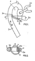
- Figure 1: is a side view of a closure arrangement according to one form of the present invention.
- Figure 2: is a plan view of a closure arrangement along the lines A-A of Figure 1 of the accompanying drawings.
- The closure arrangement of the present invention is preferably formed of an appropriate steel material, although this is by way of example only. If desired, the closure arrangement can be formed of any other appropriate material, such as for example plastics and the like.
- Referring to Figure 1 of the accompanying drawing, it will be seen that the closure arrangement is of an essentially "hook" shaped formation, including at least two spaced apart arm portions, being a first arm portion 2 and a second arm portion 3. The first arm portion 2 is essentially elongate in formation and is curved at its upper end and leads into a second, curved elongate arm portion 3. The arm portions 2 and 3 are integrally formed one with the other, and, the arm portion 3 is longer than the arm portion 2, and curves inwardly towards and under a lower end of the arm portion 2. The arm portions 2 and 3 define between them, a
closure space 4. - As shown in Figure 1 of the drawings, the first arm portion 2 is connected to a
chain 2a, which in turn can be attached to a gate or door, or the like. - In order to secure such a gate to a gate post or upright, a connector, such as a staple or substantially "U" shaped connector, is hammered or placed into, or engaged with, a gate post or upright (not shown). Thus, in order to secure a gate to a gate post or upright, such as in a closed position, the elongate arm portion 3 is slipped over the connector, so that the connector is passed up into and housed within the
closure space 4. This then serves to secure the gate in a closed position. In order to open the gate, an upward movement is applied to the arm portion 3, which will disengage the connector from within theclosure space 4, and disengage the closure arrangement from the connector. This will then allow the gate or door to open. - While this embodiment is described with reference to the closure arrangement being attached to a gate or door, and the connector to a post or upright, it should be appreciated that this is by way of example only. If desired, the closure arrangement can be mounted to a post or upright, and the connector to a gate or door.
- It will be appreciated that the prior arrangements referred to hereinbefore, which have brought about certain problems, have had a locking clip pivotally connected to a longer arm portion 2. This then means that such locking clips have up until this time, been able to pivot relative to longer arm portions 2. Thus in the engagement referred to hereinbefore, and on a connector being located within the
closure space 4, a locking clip has been pivoted out of the way to allow for location, whereafter it will move back into substantial abutment with an inner adjacent surface of a shorter arm portion, to close off the closure space and allow for some form of locking. To remove the connector 1 from within the closure space, the locking clip is pivoted out of position to allow for removal. As indicated hereinbefore, numerous problems have been associated with such arrangements. - The arrangement of the preferred embodiment of the present invention allows for a locking member in the form of a clip or ring, shown as 5 in the accompanying drawings. The locking member 5 is preferably of a substantially "U" formation, and is pivotally attached at its free ends, within locating holes 7 provided adjacent a bottom end of the first arm portion 2.
- The
free ends 5a of the locking member 5 are preferably bent or turned inwardly, so as to allow for pivotal engagement with such holes 7, the holes 7 being preferably off set relative to each other, both longitudinally relative to the longitudinal axis of the first arm portion 2 and laterally relative to each other. While it is preferred that thefree ends 5a be pivotally engaged with the first arm portion 2, so as to be both longitudinally and laterally off set, this is by way of example only. If desired, theends 5a of the locking member 5 and the holes or bores 7 can be longitudinally off set relative to each other, and/or laterally or horizontally off set relative to each other. - In the preferred form of the invention, the locking member 5 is formed of a sprung or biased material, such as for example a sprung metal material. This is however by way of example only.
- The location of the locking member 5, relative to the first arm portion 2, is shown with reference to Figures 1 and 2 of the accompanying drawings.
- The pivotal location of the locking member 5 relative to the first arm portion 2, such as in the manner referred to hereinbefore, resiliently biases the locking member 5 into a downward position in which it is resiliently biased against an inner and adjacent surface 3a of the second arm portion 3. The locking member 5 is therefore resiliently held in this position, and a positive upward movement against the spring bias, (such as in the direction of arrow "B" in Figure 1 of the drawings), is required to move the locking member out of its position with the inner adjacent surface of the second arm portion 3, to allow for both location and removal of for example a connector within the
closure space 4. It will be appreciated from Figure 2 of the drawings that ends of the closure member 5 are turned inwardly as at 5a, which ends 5a engage with offset holes or slots 7, provided in the first arm portion 2 and preferably in a lower portion of the first arm portion 2. This then causes the locking member 5 to be resiliently biased against the inner surface 3a of the second arm portion 3. - This resilient location, which requires a positive and upward movement against the bias, to move the locking member out of position, makes it very difficult for animals, people, children and the like to move the locking member 5 out of position, although a positive movement does allow for such removal, and thus predetermined use and normal operation is not hindered. The preferred embodiment of the invention does however overcome the problems as associated with animals and children, up until this time.
Claims (5)
Priority Applications (1)
| Application Number | Priority Date | Filing Date | Title |
|---|---|---|---|
| AT86301216T ATE52312T1 (en) | 1985-02-20 | 1986-02-20 | CLOSURE ARRANGEMENT. |
Applications Claiming Priority (2)
| Application Number | Priority Date | Filing Date | Title |
|---|---|---|---|
| NZ211170 | 1985-02-20 | ||
| NZ211170A NZ211170A (en) | 1985-02-20 | 1985-02-20 | Cow-proof hook-type latch for gate |
Publications (2)
| Publication Number | Publication Date |
|---|---|
| EP0192483A1 EP0192483A1 (en) | 1986-08-27 |
| EP0192483B1 true EP0192483B1 (en) | 1990-04-25 |
Family
ID=19921090
Family Applications (1)
| Application Number | Title | Priority Date | Filing Date |
|---|---|---|---|
| EP86301216A Expired - Lifetime EP0192483B1 (en) | 1985-02-20 | 1986-02-20 | Closure arrangement |
Country Status (6)
| Country | Link |
|---|---|
| EP (1) | EP0192483B1 (en) |
| AT (1) | ATE52312T1 (en) |
| AU (1) | AU584675B2 (en) |
| CA (1) | CA1275429C (en) |
| DE (1) | DE3670676D1 (en) |
| NZ (1) | NZ211170A (en) |
Families Citing this family (1)
| Publication number | Priority date | Publication date | Assignee | Title |
|---|---|---|---|---|
| AU666989B2 (en) * | 1993-12-17 | 1996-02-29 | Bulk At Wholesale Pty Ltd | Fastener for gates and the like |
Family Cites Families (5)
| Publication number | Priority date | Publication date | Assignee | Title |
|---|---|---|---|---|
| US2796279A (en) * | 1955-04-04 | 1957-06-18 | Henry C Schloer | Gate latch |
| US3827746A (en) * | 1973-01-05 | 1974-08-06 | L Byers | Safety latch for hoist hook |
| DE2448809C3 (en) | 1974-10-14 | 1982-09-09 | Hörmann, geb.Schimpfle, Kreszenz, 8938 Buchloe | Neck frame tying device for cattle |
| US4050730A (en) * | 1976-05-19 | 1977-09-27 | Akio Tada | Hook latching device |
| DE2653664C3 (en) * | 1976-11-23 | 1980-11-06 | Rud-Kettenfabrik Rieger & Dietz Gmbh U. Co, 7080 Aalen | Eye hook |
-
1985
- 1985-02-20 NZ NZ211170A patent/NZ211170A/en unknown
-
1986
- 1986-02-19 AU AU53773/86A patent/AU584675B2/en not_active Expired
- 1986-02-20 AT AT86301216T patent/ATE52312T1/en not_active IP Right Cessation
- 1986-02-20 CA CA000502349A patent/CA1275429C/en not_active Expired - Lifetime
- 1986-02-20 DE DE8686301216T patent/DE3670676D1/en not_active Expired - Fee Related
- 1986-02-20 EP EP86301216A patent/EP0192483B1/en not_active Expired - Lifetime
Also Published As
| Publication number | Publication date |
|---|---|
| AU584675B2 (en) | 1989-06-01 |
| ATE52312T1 (en) | 1990-05-15 |
| DE3670676D1 (en) | 1990-05-31 |
| AU5377386A (en) | 1986-08-28 |
| NZ211170A (en) | 1988-04-29 |
| CA1275429C (en) | 1990-10-23 |
| EP0192483A1 (en) | 1986-08-27 |
Similar Documents
| Publication | Publication Date | Title |
|---|---|---|
| US7726706B2 (en) | Latch mechanism for gates and the like | |
| US4469261A (en) | Article carrier with adjustably positionable bracket | |
| EP0786217A2 (en) | Latch | |
| US7118144B2 (en) | Padlock | |
| DE10159012A1 (en) | Suspension device for elongated objects | |
| US4445254A (en) | Hose band clip | |
| US4632201A (en) | Latch mechanism for a battery holder | |
| EP0192483B1 (en) | Closure arrangement | |
| US5785365A (en) | Anti-snagging striker | |
| US4843845A (en) | Padlock shackle and hasp staple protector | |
| US4082331A (en) | Door for a mine stopping | |
| US7000292B2 (en) | Chain keeper and method of retaining a chain | |
| GB9815994D0 (en) | Improved catch mechanism | |
| US5960519A (en) | Vehicle rear lift gate hinge and counterbalance assembly | |
| US5409276A (en) | Readily releasable hasp and staple | |
| US3893724A (en) | Gate locking device | |
| US4762346A (en) | Peripherally arrayed closure fastener system | |
| US4772053A (en) | Storage chamber cross bar assembly | |
| JPH07505196A (en) | Rod locks especially for switchgear doors | |
| US5076624A (en) | Door chain device | |
| GB2197376A (en) | Safety barrier with openable gate | |
| US2792247A (en) | Door edge lock clip | |
| SE9900491D0 (en) | Device for fencing systems | |
| US4548433A (en) | Latch mechanism | |
| US4399635A (en) | Removable gate |
Legal Events
| Date | Code | Title | Description |
|---|---|---|---|
| PUAI | Public reference made under article 153(3) epc to a published international application that has entered the european phase |
Free format text: ORIGINAL CODE: 0009012 |
|
| AK | Designated contracting states |
Kind code of ref document: A1 Designated state(s): AT BE CH DE FR GB IT LI LU NL SE |
|
| 17P | Request for examination filed |
Effective date: 19870216 |
|
| 17Q | First examination report despatched |
Effective date: 19880314 |
|
| RAP1 | Party data changed (applicant data changed or rights of an application transferred) |
Owner name: FRANKLIN MACHINERY LIMITED |
|
| GRAA | (expected) grant |
Free format text: ORIGINAL CODE: 0009210 |
|
| ITF | It: translation for a ep patent filed |
Owner name: SOCIETA' ITALIANA BREVETTI S.P.A. |
|
| AK | Designated contracting states |
Kind code of ref document: B1 Designated state(s): AT BE CH DE FR GB IT LI LU NL SE |
|
| REF | Corresponds to: |
Ref document number: 52312 Country of ref document: AT Date of ref document: 19900515 Kind code of ref document: T |
|
| REF | Corresponds to: |
Ref document number: 3670676 Country of ref document: DE Date of ref document: 19900531 |
|
| ET | Fr: translation filed | ||
| PLBE | No opposition filed within time limit |
Free format text: ORIGINAL CODE: 0009261 |
|
| STAA | Information on the status of an ep patent application or granted ep patent |
Free format text: STATUS: NO OPPOSITION FILED WITHIN TIME LIMIT |
|
| 26N | No opposition filed | ||
| PGFP | Annual fee paid to national office [announced via postgrant information from national office to epo] |
Ref country code: CH Payment date: 19930218 Year of fee payment: 8 |
|
| PGFP | Annual fee paid to national office [announced via postgrant information from national office to epo] |
Ref country code: LU Payment date: 19930224 Year of fee payment: 8 |
|
| PGFP | Annual fee paid to national office [announced via postgrant information from national office to epo] |
Ref country code: AT Payment date: 19930226 Year of fee payment: 8 |
|
| ITTA | It: last paid annual fee | ||
| PGFP | Annual fee paid to national office [announced via postgrant information from national office to epo] |
Ref country code: BE Payment date: 19930318 Year of fee payment: 8 |
|
| EPTA | Lu: last paid annual fee | ||
| PG25 | Lapsed in a contracting state [announced via postgrant information from national office to epo] |
Ref country code: LU Free format text: LAPSE BECAUSE OF NON-PAYMENT OF DUE FEES Effective date: 19940220 Ref country code: AT Effective date: 19940220 |
|
| PGFP | Annual fee paid to national office [announced via postgrant information from national office to epo] |
Ref country code: DE Payment date: 19940222 Year of fee payment: 9 |
|
| PG25 | Lapsed in a contracting state [announced via postgrant information from national office to epo] |
Ref country code: LI Effective date: 19940228 Ref country code: CH Effective date: 19940228 Ref country code: BE Effective date: 19940228 |
|
| PGFP | Annual fee paid to national office [announced via postgrant information from national office to epo] |
Ref country code: NL Payment date: 19940228 Year of fee payment: 9 |
|
| BERE | Be: lapsed |
Owner name: FRANKLIN MACHINERY LTD Effective date: 19940228 |
|
| REG | Reference to a national code |
Ref country code: CH Ref legal event code: PL |
|
| EAL | Se: european patent in force in sweden |
Ref document number: 86301216.7 |
|
| PGFP | Annual fee paid to national office [announced via postgrant information from national office to epo] |
Ref country code: SE Payment date: 19950228 Year of fee payment: 10 Ref country code: FR Payment date: 19950228 Year of fee payment: 10 |
|
| PGFP | Annual fee paid to national office [announced via postgrant information from national office to epo] |
Ref country code: GB Payment date: 19950303 Year of fee payment: 10 |
|
| PG25 | Lapsed in a contracting state [announced via postgrant information from national office to epo] |
Ref country code: NL Effective date: 19950901 |
|
| NLV4 | Nl: lapsed or anulled due to non-payment of the annual fee |
Effective date: 19950901 |
|
| PG25 | Lapsed in a contracting state [announced via postgrant information from national office to epo] |
Ref country code: DE Effective date: 19951101 |
|
| PG25 | Lapsed in a contracting state [announced via postgrant information from national office to epo] |
Ref country code: GB Effective date: 19960220 |
|
| PG25 | Lapsed in a contracting state [announced via postgrant information from national office to epo] |
Ref country code: SE Effective date: 19960221 |
|
| GBPC | Gb: european patent ceased through non-payment of renewal fee |
Effective date: 19960220 |
|
| PG25 | Lapsed in a contracting state [announced via postgrant information from national office to epo] |
Ref country code: FR Effective date: 19961031 |
|
| REG | Reference to a national code |
Ref country code: FR Ref legal event code: ST |
|
| PG25 | Lapsed in a contracting state [announced via postgrant information from national office to epo] |
Ref country code: IT Free format text: LAPSE BECAUSE OF NON-PAYMENT OF DUE FEES;WARNING: LAPSES OF ITALIAN PATENTS WITH EFFECTIVE DATE BEFORE 2007 MAY HAVE OCCURRED AT ANY TIME BEFORE 2007. THE CORRECT EFFECTIVE DATE MAY BE DIFFERENT FROM THE ONE RECORDED. Effective date: 20050220 |