EP0192211A2 - Sheet counter and stacker system - Google Patents
Sheet counter and stacker system Download PDFInfo
- Publication number
- EP0192211A2 EP0192211A2 EP86101941A EP86101941A EP0192211A2 EP 0192211 A2 EP0192211 A2 EP 0192211A2 EP 86101941 A EP86101941 A EP 86101941A EP 86101941 A EP86101941 A EP 86101941A EP 0192211 A2 EP0192211 A2 EP 0192211A2
- Authority
- EP
- European Patent Office
- Prior art keywords
- sheets
- conveyor
- stream
- shingled
- stacking
- Prior art date
- Legal status (The legal status is an assumption and is not a legal conclusion. Google has not performed a legal analysis and makes no representation as to the accuracy of the status listed.)
- Withdrawn
Links
Images


Classifications
-
- B—PERFORMING OPERATIONS; TRANSPORTING
- B65—CONVEYING; PACKING; STORING; HANDLING THIN OR FILAMENTARY MATERIAL
- B65H—HANDLING THIN OR FILAMENTARY MATERIAL, e.g. SHEETS, WEBS, CABLES
- B65H33/00—Forming counted batches in delivery pile or stream of articles
- B65H33/12—Forming counted batches in delivery pile or stream of articles by creating gaps in the stream
-
- B—PERFORMING OPERATIONS; TRANSPORTING
- B65—CONVEYING; PACKING; STORING; HANDLING THIN OR FILAMENTARY MATERIAL
- B65H—HANDLING THIN OR FILAMENTARY MATERIAL, e.g. SHEETS, WEBS, CABLES
- B65H29/00—Delivering or advancing articles from machines; Advancing articles to or into piles
- B65H29/66—Advancing articles in overlapping streams
- B65H29/6609—Advancing articles in overlapping streams forming an overlapping stream
- B65H29/6618—Advancing articles in overlapping streams forming an overlapping stream upon transfer from a first conveyor to a second conveyor advancing at slower speed
- B65H29/6627—Advancing articles in overlapping streams forming an overlapping stream upon transfer from a first conveyor to a second conveyor advancing at slower speed in combination with auxiliary means for overlapping articles
-
- B—PERFORMING OPERATIONS; TRANSPORTING
- B65—CONVEYING; PACKING; STORING; HANDLING THIN OR FILAMENTARY MATERIAL
- B65H—HANDLING THIN OR FILAMENTARY MATERIAL, e.g. SHEETS, WEBS, CABLES
- B65H29/00—Delivering or advancing articles from machines; Advancing articles to or into piles
- B65H29/70—Article bending or stiffening arrangements
-
- B—PERFORMING OPERATIONS; TRANSPORTING
- B65—CONVEYING; PACKING; STORING; HANDLING THIN OR FILAMENTARY MATERIAL
- B65H—HANDLING THIN OR FILAMENTARY MATERIAL, e.g. SHEETS, WEBS, CABLES
- B65H31/00—Pile receivers
- B65H31/26—Auxiliary devices for retaining articles in the pile
-
- G—PHYSICS
- G06—COMPUTING; CALCULATING OR COUNTING
- G06M—COUNTING MECHANISMS; COUNTING OF OBJECTS NOT OTHERWISE PROVIDED FOR
- G06M1/00—Design features of general application
- G06M1/08—Design features of general application for actuating the drive
- G06M1/10—Design features of general application for actuating the drive by electric or magnetic means
- G06M1/101—Design features of general application for actuating the drive by electric or magnetic means by electro-optical means
-
- B—PERFORMING OPERATIONS; TRANSPORTING
- B65—CONVEYING; PACKING; STORING; HANDLING THIN OR FILAMENTARY MATERIAL
- B65H—HANDLING THIN OR FILAMENTARY MATERIAL, e.g. SHEETS, WEBS, CABLES
- B65H2301/00—Handling processes for sheets or webs
- B65H2301/40—Type of handling process
- B65H2301/42—Piling, depiling, handling piles
- B65H2301/421—Forming a pile
- B65H2301/4212—Forming a pile of articles substantially horizontal
-
- Y—GENERAL TAGGING OF NEW TECHNOLOGICAL DEVELOPMENTS; GENERAL TAGGING OF CROSS-SECTIONAL TECHNOLOGIES SPANNING OVER SEVERAL SECTIONS OF THE IPC; TECHNICAL SUBJECTS COVERED BY FORMER USPC CROSS-REFERENCE ART COLLECTIONS [XRACs] AND DIGESTS
- Y10—TECHNICAL SUBJECTS COVERED BY FORMER USPC
- Y10S—TECHNICAL SUBJECTS COVERED BY FORMER USPC CROSS-REFERENCE ART COLLECTIONS [XRACs] AND DIGESTS
- Y10S414/00—Material or article handling
- Y10S414/10—Associated with forming or dispersing groups of intersupporting articles, e.g. stacking patterns
- Y10S414/115—Associated with forming or dispersing groups of intersupporting articles, e.g. stacking patterns including article counter
Definitions
- the counting means controls the operation of the stacker and which stacker also provides an improved means for separating and stacking preselected quantities of sheets in such a way as to avoid jamming the system.
- Previous stacking systems which did not employ any type of counting means would normally be controlled or operated by the delivery or folding system which feeds into the stacker. Under such an arrangement, however, the stacker would continue operating as long as the delivery or folding system was operating.
- the stacker can be actuated by the sheet counting means which can shut down the stacker when the flow of sheets is completed. Operation in this manner avoids the necessity of employing labor to solely operate the stacking system.
- the device of this invention counts and stacks sheets of printed material and is intended to be integrated into a full service printing system.
- the device of this invention will follow the actual printing and folding and cutting operation and will receive a continuous stream of shingled or overlapping sheets for counting and stacking into predetermined quantities. Subsequent to stacking, but not a part of this invention, the sheets would generally be bundled in some manner for easy handling and movement.
- the sheets As the shingled sheets are received by the invention, they travel by a first conveyor means where they are then fed into the optical counting means for counting. After exiting the counting means, the sheets enter a second conveyor means where a transverse bow is imparted to the sheets. The sheets travel along the second conveyor in bowed relation and exit the second conveyor where they fall individually onto a sheet receiving means.
- the sheet receiving means acts as a table on which the stack of sheets forms.
- an elongated spade underlying the second conveyor extends into the stream of overlapping sheets. The spade acts as a temporary sheet receiving means while the completed stack is removed from the actual sheet receiving means.
- the belt 30 is tensioned by means of a pulley 38 rotatably attached to one end of a tensioning bracket 40 by a pin 42.
- the pulley 38 is adjustably positionable by pivotal movement of the bracket 40 about a pin 44 fixably attached to the frame 11.
- a lug nut 48 receptively engages the lug 47 and locks the tensioning bracket 40 in position.
- the main drive shaft 34 is caused to rotate by the movement of a main timing belt pulley 50, suitably key connected' to the main drive shaft 34.
- the main timing belt pulley 50 is driven by a timing belt 52 which engages a second gear 54 that is key connected to the shaft 56 of a belt drive motor 58.
- the timing belt 52 is tensioned by adjustably positioning the motor 58 by means of the adjustable motor mounting bracket 60.
- the shingled sheets are supported in movement between the guide roller 15 and drive roller 17 by the belts 14. Disposed directly above the drive roller 17 and. laterally between the belts 14 is a guide plate 62 with a downwardly curved leading edge for easily receiving the flow of shingled sheets and for supporting the sheets immediately preceding the entry of the sheets into the counting means 70.
- the guide plate 62 is mounted to the frame 11 by a bracket 64 which has a longitudinal slot 66 for vertically positioning the guide plate 62 on the threaded lugs 68 which are fixably attached to the frame 11 and extend through the slot 66.
- the sides of the frame 78 have a pair of arcuate shaped slots 84 through which a threaded lug 86 mounted to the main frame 11 is positioned.
- the frame 78 is free to pivot about the axle of the drive roller 39 limited by the interaction of the lug 86 and the slot 84.
- the frame 78 is locked in place by a lug nut 88 tightened about the lug 86.
- the impinging roller 80 is spring loaded by springs 90 affixed to the upper portion of the frame 78 and the impinging roller axle 82 to be subject to a constant downward force relative to the sides of the frame 78 (Figs. 1, 2A).
- the ends of the impinging roller axle 82 ride in a second pair of slots 92 provided in the sides of the frame 78 allowing translational movement of the impinging roller relative to the sides of the frame 78.
- the frame 78 in an upright or vertical position, i.e., with the impinging roller 80 directly vertically above the drive roller 36, the trailing edge of the sheets are not flipped down and, therefore, the sheets are not counted. This allows the operator to run waste or test sheets through the machine without needing to reset the counting mechanism.
- a transverse bow is imparted on the flat stream of shingled sheets as they are received by the entry guide plate 74 of a second conveyor 100 and fed into an initial dual pair of angled rollers 120 and 102 (Figs. 2A, 4).
- the guide plate 74 is mounted to the frame 11 by a bracket 96 which has a longitudinal slot 97 for vertically positioning the guide plate 74 on the threaded lugs 98 which are fixably attached to the frame 11 and extend through the slot 97.
- the dual pair of rollers are comprised of bottom rollers 102 which are rotatably mounted on inwardly angled shafts 104 which, in turn, are attached to frame 11 by brackets 106.
- a pair of universal joints 108 and 109 are attached to the rollers 102 and are interconnected for unison movement by axle 110.
- the universal joints 108 and 109 engage the center of pulleys 112 and 113 and are driven by belts 114.
- the belts 114 are, in turn, driven by a second set of pulleys 116 and 117 attached to and driven by the main drive shaft 34.
- In complemental relationship to the rollers 102 is a pair of floating guide rollers 120. These guide rollers 120 rotate freely about one end of the arms 124.
- the other end of arms 124 pivot about inwardly angled posts 126 mounted to frame 11 by brackets 128 allowing the rollers 120 to be lifted off of the surface of the second conveyor 100 providing unobstructed access to the shingled sheets.
- the transverse bow adds rigidity and strength to the sheets not characteristic in a stream of flat sheets.
- the transverse bow imparted to the sheets is maintained in the second conveyor 100 by means of an intermediate deck plate 130, two side deck plates 132 and a second dual pair of rollers 134 and 136.
- a cut out portion 138 runs the length of the deck plate 130 on each side defining a raised, elongated spade shaped member 131 and further-allowing the surfaces of the side deck plates 132 to align evenly with the surface of the spade 131.
- the side plates 132 are positioned by angled brackets 140 affixed to the frame 11 by bolts 142.
- the upper floating guide rollers 136 are rotatably mounted to one end of the arms 146.
- one of the four threaded shafts 180 is driven by a variable speed, reversible motor 190 through the rotation or counter rotation of the motor shaft 192 operably connected to a snub shaft 194 by a coupling 196, which snub shaft 194 rotates within a bearing sleeve 198 and drives right angle bevel gears 200 and 201 causing the threaded shaft 180 to rotate.
- the motor 190 is supported by a pedestal 202 and positionably attached to the frame 11 by base plates 204.
- the motor shaft 192 and right angled gears 200 and 201 are disposed within protective housings 206 and 208. Accordingly, the entire piston cylinder and intermediate deck plate structure is vertically positionable within the frame 11.
- the shingled sheets are propelled out of the second conveyor 100 wherein the individual sheets hit the front stops 228 and fall upon a sheet receiving means 226.
- the sheets are confined during the fall by front stops 228, side joggers 230 and back joggers 232.
- the front stops 228 are affixed to a front frame mount 234 which is attached to the frame 11 by bolts 236.
- the side joggers 230 and the back joggers 232 neatly position the sheets on the receiving means 226.
- the joggers oscillate by means well known to those of skill in the art from motion of the main drive shaft 34 transferred to the joggers by a belt and pulley system.
- a lug nut 251 receptively engages the lug 249 and locks the tensioning bracket 241 in position.
- the entire deck plate 130 then descends at a rate faster than the descending receiving means 226. This allows the top of the newly forming stack on the spade 131 to be lower than the incoming sheets and further allows the deck plate 130 to compress the stack of sheets on the slower descending receiving means 226 thereby removing any air in the completed stack for subsequent bundling. Air trapped within the sheets can add several inches or more to the overall height of a stack of sheets depending upon the weight of the paper used and the height of the stack. When heavier stock paper is used, less air is trapped during stacking thereby alleviating the necessity of compressing the stack. In such a circumstance, the timing of the movement of the receiving means 226 relative to the deck plate 130 can be adjusted.
- the receiving means 226 ascends to a position just below the now stationary and fully extended spade 131.
- the spade 131 is then retracted by its controlling piston-cylinder structure 168 causing the sheets to drop onto the sheet receiving means 226.
- the preferred embodiment includes a pair of back plates 326 mounted to frame 11 to aid in stripping the newly forming stack of sheets from the spade 131 causing the sheets to drop onto the receiving means 226.
- the deck plate 130 and piston-cylinder structure 168 then ascend to realign the spade 131 between the side plates 132.
- the present embodiment could also be used with a second conveyor that transports the sheets in a substantially flat relaticnship rather then bowed as in the preferred embodiment.
- the additional impinging roller rather than helping form a pocket for insertion of the spade 131, will cause the entire trailing edge of each succeeding flat sheet to flip down off the conveyor while still securely positioned by the last dual pair of rollers 162 and 160. This will provide the necessary space for the spade to be inserted from below and beneath without any jamming or fouling of the system.
Abstract
A system for counting and stacking a continuous stream of shingled or overlapping sheets in which the shingled sheets are transported by a first conveyor and fed into an optional counting means for individually counting the sheets. From the optical counting means, the sheets are fed into a second conveyor which imparts a concave transverse bow to the sheets thereby providing rigidity to the sheets. The sheets exit the second conveyor and are collected by a recovery means for stacking. The second conve..or further includes an insertion means activated by the optical counter for separating the stream of sheets. The action of the insertion means separates the stream of sheets so that a predetermined number of sheets are collected and stacked by the receiving means while the insertion means temporarily supports the continuing stream of sheets. After removal of the completed stack of sheets, the insertion means retracts to its original position thereby transferring the newly forming stack of sheets to the receiving means without interrupting the continuous stream of sheets.
Description
- The present invention relates to an improved system for counting and stacking sheets of paper or signatures and would normally be used in conjunction with a printing process. In the printing process, a continuous sheet or web of paper is processed by first passing it through the printing process; second, passing it through an oven to dry the web and remove solvents and ink resins; third, passing the web through a folding and cutting system to transform the printed web into a series of shingled or overlapping individual sheets; and, finally, conveying the shingled sheets into a counting and stacking system to count and stack the sheets into stacks of a predetermined number of sheets.
- It is desirable to provide a counting and stacking system in which the counting means controls the operation of the stacker and which stacker also provides an improved means for separating and stacking preselected quantities of sheets in such a way as to avoid jamming the system. Previous stacking systems which did not employ any type of counting means would normally be controlled or operated by the delivery or folding system which feeds into the stacker. Under such an arrangement, however, the stacker would continue operating as long as the delivery or folding system was operating. With the present invention, the stacker can be actuated by the sheet counting means which can shut down the stacker when the flow of sheets is completed. Operation in this manner avoids the necessity of employing labor to solely operate the stacking system.
- The prior art discloses various types of devices for stacking sheets. Particularly, these prior devices make use of wedges or other insertion means to separate the continuous flow of sheets into distinct stacks by inserting the wedge in the direction opposite sheet flow. See, U.S. Patent Nos. 3,566,757 and 3,568,578. The inherent problem in separating sheets in a direction opposite sheet flow is that such a method of separation creates a high probability of lead edge fouling or inaccurate segregation of sheets.
- Other prior art devices separate sheets from beneath and in the same direction of sheet flow. However, these devices employ more than one insertion means. See, U.S. Patent No. 2,853,299, U.S. Patent No. 4,359,218 and U.S. Patent No. 4,111,411. The present invention overcomes the problems and limitations associated with these prior devices and improves upon the prior art stackers by achieving separation and stacking of the sheets through the use of a single insertion device from beneath and in the direction of sheet flow.
- The preferred embodiment of the present invention also employs an optical counting system to count the sheets. A transmitter emits a beam of light which, when interrupted, causes a counter to register a counted unit. Optical counters have been previously used to count sheets as seen in U.S. Patent No. 3,834,289. However, the present invention improves upon previous optical counting arrangements. In U.S. Patent No. 3,834,289, for example, the feed conveyor is angled and is required to be elevated above the conveyor discharging the sheets from the counter. The present invention alleviates all of the common problems associated with angled and dual level conveyors by using a level conveyor system while still achieving accurate counting.
- It is a general object of this invention to provide an improved sheet counting and stacking system for use in connection with printing processes.
- It is a furthe: object of this invention to provide an improved stacking means.
- It is another object of this invention to provide an improved means for individually and accurately counting sheets.
- It is another object of this invention to provide stacking means which separates the continuous flow of sheets from beneath and behind the sheets and which additionally bows the shingled sheets thereby making separation of predetermined quantities of sheets accurate and less susceptible to jamming and which further imparts an increased stiffness to the sheets.
- It is still a further object of this invention to control operation of the improved stacking means by means of an optical sheet counter.
- In accordance with one embodiment, a continuous stream of shingled sheets is caused to travel by a first conveyor at a constant, slow speed relative to the speed of the web exiting the printing press. The sheets then enter a counting means wherein the stream of sheets are forced beneath a roller and are individually counted as the trailing edge of each sheet is flipped down to interrupt an optical counter. The optical counter can also serve as a control for the subsequent stacker system. That is, when no shingles are present to be counted as sensed by the optical counter, the stacker may be shut down.
- From the counter, the continuous shingled stream of sheets is carried over a second multi-belt conveyor. This second conveyor section includes driven belts as well as driven and guide rollers at each side of the sheet path, angled inwardly to impart a transverse bow to the sheets. This conveyor is also provided with an intermediate deck plate to assist in support of the center of the bowed sheets. The center portion of the deck plate is formed by an elongated spade with a forward nose disposed at the exit end of the second conveyor. The spade, in its resting position, extends for a distance less than the full length of the second conveyor.
- As the bowed and shingled sheets are transported along the second conveyor and over the forward nose of the elongated spade, the trailing edges of the bowed sheets snap downwardly past the nose of the spade. Because the sheets are no longer supported beneath their centerline at this point, the sheets bow even further creating a pocket between the sheet which has completely passed over the spade and the next trailing sheet which has not yet snapped downwardly past the nose of the spade. The sheets then exit the second conveyor and fall upon a sheet receiving means where jogging means maintain an even alignment in the individual sheets.
- When a predetermined number of sheets have been counted, the elongated spade is activated. The spade extends in the direction of sheet flow and is inserted into the pocket formed between the trailing edge of the last sheet to flip past the nose of the spade and the following sheet that is still supported by the nose of the spade. The spade may be operated by means of a piston-cylinder arrangement as is well known. Under the actuation of the optical counter, the spade periodically reciprocates to separate the sheet stream into stacks of preselected quantities.
- The spade continues its horizontal extension into the sheet stream until it contacts a limit switch, at which position the spade will be directly over the sheet receiving means. A typical embodiment of the sheet receiving means may be an air table. The extended spade provides a temporary floor on which the continuing flow of sheets can form a new stack. Both the spade, with the newly forming stack, and the air table, with the completed stack of sheets, are lowered. The spade is lowered so that the height of the newly forming stack does not surpass the plane of the second conveyor, thereby jamming the system. The air table is lowered until it is slightly above a second sheet receiving means or stack transport table. The stack transport table also may typically be an air table. The completed stack is removed from the air table or relocated to the second air table by movement of a second piston-cylinder arrangement. The spade then retracts to its original position leaving the uncompleted stack of sheets on the air table to form a completed stack.
- For a more complete understanding of this invention, reference should now be made to the embodiment illustrated in greater detail in the accompanying drawings and described below by way of examples of the invention.
-
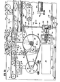
- Figure 1 is a perspective view of the sheet counter and stacker system of this invention.
- Figure 2A is a cross-sectional side view of the counting means and a portion of the stacking means.
- Figure 2B is a cross-sectional side view of the remainder of the stacking means not shown in Figure 2A.
- Figure 3 is an incomplete cross-sectional view taken along line 3-3 of Figure 2A.
- Figure 4 is an incomplete cross-sectional view taken along line 4-4 of Figure 2A.
- Figure 5 is an incomplete cross-sectional side view of the operative elements comprising the stacking means of this invention.
- Figure 6 is a cross-sectional view of the optical counting means.
- Figure 7 is an incomplete cross-sectional end view taken along line 7-7 of Figure 2B.
- Figure 8 is a cross-sectional side view of the optical counting means.
- The relationship and workings of the various elements of this invention will be better understood by the following detailed description. However, the embodiment of the invention described below is by way of example only and applicant does not limit himself to this embodiment. Furthermore, one should understand that the drawings are not to scale and that the embodimen@s are illustrated by graphic symbols and fragmentary views. In certain instances, the applicant may have omitted details which are not necessary for an understanding of the present invention such as conventional details of fabrication and assembly.
- Generally, the device of this invention counts and stacks sheets of printed material and is intended to be integrated into a full service printing system. The device of this invention will follow the actual printing and folding and cutting operation and will receive a continuous stream of shingled or overlapping sheets for counting and stacking into predetermined quantities. Subsequent to stacking, but not a part of this invention, the sheets would generally be bundled in some manner for easy handling and movement.
- As the shingled sheets are received by the invention, they travel by a first conveyor means where they are then fed into the optical counting means for counting. After exiting the counting means, the sheets enter a second conveyor means where a transverse bow is imparted to the sheets. The sheets travel along the second conveyor in bowed relation and exit the second conveyor where they fall individually onto a sheet receiving means. The sheet receiving means acts as a table on which the stack of sheets forms. When the predetermined number of sheets have been counted, an elongated spade underlying the second conveyor extends into the stream of overlapping sheets. The spade acts as a temporary sheet receiving means while the completed stack is removed from the actual sheet receiving means.
- It should be understood that many of the elements depicted in the cross-sectional drawings of Figures 2A and 2B are symetric about the centerline of the sheet counter and stacker system. It is inherent with respect to these elements that duplicative elements exist on the opposite side of the conveyor which are not shown in Figures 2A and 2B but which appear in the other figures. In those instances, the elements are described only once but are referenced in plural rather than singular to indicate the existence of duplicative elements.
- Described in more detail, a stream of flat shingled sheets, wherein the leading edge of each sheet overlaps the tail of the preceding sheet, is fed into the counter and
stacker system 10 of this invention (Fig. 1) by means of a first (Fig. 2A)conveyor 12 comprising a series offlat belts 14 traversing aguide roller 15 and drive roller 17. Both theguide roller 15 and the drive roller 17 are rotatably mounted to theframe 11 by means ofaxles 16 and 18, respectively, and the drive roller 17 has a channel cut through the center (not shown). Thebelts 14 are further subject to variable tensioning by means of adjustablypositionable pulleys 22 rotatably attached to ashaft 24, which engagearms 26 pivotally mounted to theframe 11 bypins 28. Thebelts 14 are driven by the drive roller 17 which, in turn, is driven by abelt 30 operably engaging a pulley 32 and rotatably engaging apulley 33 attached to amain drive shaft 34. Thisbelt 30 drives still anotherroller 36 by means of a pulley 37 affixed to theaxle 39 of theroller 36 which forms a part of the sheet counting means 70 discussed in detail below. The surfaces of the pulleys 32 and 37 are recessed below the surfaces of the drive roller 17 andother roller 36, respectively, so not to interfere with the movement of the shingled sheets. - The
belt 30 is tensioned by means of a pulley 38 rotatably attached to one end of a tensioning bracket 40 by a pin 42. The pulley 38 is adjustably positionable by pivotal movement of the bracket 40 about a pin 44 fixably attached to theframe 11. An arcuate slot 46 at the opposite end of the bracket 40 through which extends a threaded lug 47, fixably attached to theframe 11, limits movement of the bracket 40. A lug nut 48 receptively engages the lug 47 and locks the tensioning bracket 40 in position. - The
main drive shaft 34 is caused to rotate by the movement of a maintiming belt pulley 50, suitably key connected' to themain drive shaft 34. The maintiming belt pulley 50 is driven by atiming belt 52 which engages a second gear 54 that is key connected to theshaft 56 of abelt drive motor 58. Thetiming belt 52 is tensioned by adjustably positioning themotor 58 by means of the adjustablemotor mounting bracket 60. - The shingled sheets are supported in movement between the
guide roller 15 and drive roller 17 by thebelts 14. Disposed directly above the drive roller 17 and. laterally between thebelts 14 is aguide plate 62 with a downwardly curved leading edge for easily receiving the flow of shingled sheets and for supporting the sheets immediately preceding the entry of the sheets into the counting means 70. Theguide plate 62 is mounted to theframe 11 by abracket 64 which has alongitudinal slot 66 for vertically positioning theguide plate 62 on the threaded lugs 68 which are fixably attached to theframe 11 and extend through theslot 66. - As seen additionally in Figure 8, the optical counting means 70 is comprised of a
photoelectric transmitter 72 fixably attached to and subtending theentry guide plate 74 of a second conveyor 100 and areceiver 76 fixably attached to and subtending theguide plate 62, and apositionable frame 78 supportably housing adrive roller 36 disposed below an impingingroller 80, both rotatable aboutrespective axles frame 78. Of course, it is understood that the respective positions of the photoelectric transmitter and receiver may be reversed. Thedrive roller axle 39 further extends through theframe 78 and is mounted to each side of themain frame 11. The sides of theframe 78 have a pair of arcuate shapedslots 84 through which a threadedlug 86 mounted to themain frame 11 is positioned. Theframe 78 is free to pivot about the axle of thedrive roller 39 limited by the interaction of thelug 86 and theslot 84. Theframe 78 is locked in place by alug nut 88 tightened about thelug 86. The impingingroller 80 is spring loaded bysprings 90 affixed to the upper portion of theframe 78 and the impingingroller axle 82 to be subject to a constant downward force relative to the sides of the frame 78 (Figs. 1, 2A). The ends of the impingingroller axle 82 ride in a second pair ofslots 92 provided in the sides of theframe 78 allowing translational movement of the impinging roller relative to the sides of theframe 78. - Drive is imparted to the
lower roller 36 by means of thebelt 30 which drives thefirst conveyor 12. A pulley 37 mounted on one end of thedrive roller axle 39 engages thebelt 30 which is powered by themain drive shaft 34. A channel found in the center of thedrive roller 36 allows light emitted from aphotoelectric transmitter 72 to pass through and be received by aphotoelectric receiver 76. - In operation, the flat shingled sheets cross the
guide plate 62 with each successive leading edge forced between thedrive roller 36 and the impingingroller 80. As seen in Figure 8, the relative positioning of thedrive roller 36 and the impingingroller 80 by adjustable positioning of theframe 78, as explained above, cause the sheets to be forced beneath the impingingroller 80 and then over thedrive roller 36. The action of the impingingroller 80 flattens the spine of the sheets created during a prior folding operation. - Often the sheets will collect static from handling prior to entering the sheet counter and stacker system of this invention. Depending on the polarity, this static can push the sheets apart or force them together creating fouling problems in the system. The static is minimized, however, by the positioning of the rollers so that as the sheets travel between the impinging
roller 80 and thedrive roller 36 the respective leading edges are driven upwardly introducing air back between the successive sheets. This upward movement of the leading edge of the sheets, together with the positioning of theguide plate 62 cause each trailing edge of each succeeding sheet to be flipped down as the sheet leaves theguide plate 62, thereby briefly interrupting the light beam emitted from thephotoelectric transmitter 72 and causing the sheets to be individually counted. Alternatively, by positioning theframe 78 in an upright or vertical position, i.e., with the impingingroller 80 directly vertically above thedrive roller 36, the trailing edge of the sheets are not flipped down and, therefore, the sheets are not counted. This allows the operator to run waste or test sheets through the machine without needing to reset the counting mechanism. - A transverse bow is imparted on the flat stream of shingled sheets as they are received by the
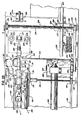
entry guide plate 74 of a second conveyor 100 and fed into an initial dual pair ofangled rollers 120 and 102 (Figs. 2A, 4). Theguide plate 74 is mounted to theframe 11 by abracket 96 which has alongitudinal slot 97 for vertically positioning theguide plate 74 on the threaded lugs 98 which are fixably attached to theframe 11 and extend through theslot 97. The dual pair of rollers are comprised ofbottom rollers 102 which are rotatably mounted on inwardlyangled shafts 104 which, in turn, are attached to frame 11 bybrackets 106. A pair ofuniversal joints rollers 102 and are interconnected for unison movement byaxle 110. Theuniversal joints pulleys belts 114. Thebelts 114 are, in turn, driven by a second set ofpulleys main drive shaft 34. In complemental relationship to therollers 102 is a pair of floatingguide rollers 120. These guiderollers 120 rotate freely about one end of thearms 124. The other end ofarms 124 pivot about inwardlyangled posts 126 mounted to frame 11 bybrackets 128 allowing therollers 120 to be lifted off of the surface of the second conveyor 100 providing unobstructed access to the shingled sheets. The transverse bow adds rigidity and strength to the sheets not characteristic in a stream of flat sheets. - As seen in Figure 3, the transverse bow imparted to the sheets is maintained in the second conveyor 100 by means of an
intermediate deck plate 130, twoside deck plates 132 and a second dual pair ofrollers portion 138 runs the length of thedeck plate 130 on each side defining a raised, elongated spade shapedmember 131 and further-allowing the surfaces of theside deck plates 132 to align evenly with the surface of thespade 131. Theside plates 132 are positioned byangled brackets 140 affixed to theframe 11 bybolts 142. The upper floatingguide rollers 136 are rotatably mounted to one end of thearms 146. The other end of thearms 146 pivot about the end of inwardlyangled posts 148 to allow theupper rollers 136 to be lifted off the surface of the second conveyor 100 providing access to the sheets. Theposts 148 are fixed to theframe 11 bybrackets 150. The bowed sheets are transported along the support plates by means offlat belts 152 which encircle the drive rollers 102 (Fig. 4), theside plates 132, theend rollers 162 and thelower guide rollers 134. - The
lower guide rollers 134 are rotatably mounted on the ends of inwardly angled posts 154. Theposts 154 are fixed to theframe 11 bybrackets 156. - Subtending and attached to the intermediate deck plate is a "T"
bracket 164 which is operably connected to apiston 166 disposed within acylinder 168 by an interconnecting plate 170 which reciprocates in a self sealing slot (not shown) running the length of the upper surface of thecylinder 168. A piston-cylinder structure of this type is manufactured by Origa, No. 120S-20, having an eighteen-inch stroke. Disposed at each end of the cylinder 168 (Figs. 2A, 2B, 5) areend blocks 174 which receive pressurized air from an air source (not shown). These brackets are affixed to supportbrackets 176. Subtending eachsupport bracket 176 are two internally threaded bushings 178 (Figs. 2A, 2B, 3) which receptively engage threadedshafts 180 and are freely rotatable inbrackets brackets 182 are secured to theframe 11 by the mountingplates 181. Attached to each threadedshaft 180 directly above the respectivebase mounting brackets 183 are fourpulleys 184 interconnected by abelt 186.Belt 186 is tensioned by an adjustablypositionable pulley 185 mounted in one of the base brackets 183 (Fig. 2A). Driving any one of the four threadedshafts 180 will uniformly rotate all fourshafts 180 thereby engaging thebushings 178 and ascendingly or descendingly positioning thecylinder 168. As seen in Figure 2A, one of the four threadedshafts 180 is driven by a variable speed,reversible motor 190 through the rotation or counter rotation of themotor shaft 192 operably connected to asnub shaft 194 by acoupling 196, whichsnub shaft 194 rotates within abearing sleeve 198 and drives rightangle bevel gears shaft 180 to rotate. Themotor 190 is supported by apedestal 202 and positionably attached to theframe 11 by base plates 204. Themotor shaft 192 and rightangled gears protective housings frame 11. - As seen in Figures 1 and 6, a third dual pair of
rollers bottom rollers 162 are rotatably mounted on downwardlyangled posts 210 attached to theframe 11 bybrackets 212.Upper rollers 160 freely rotate about one end ofarms 216. The other end ofarms 216 pivot about inwardlyangled posts 220 mounted to theframe 11 bybrackets 222 to allow theupper rollers 160 to be lifted off the surface of the second conveyor 100 thereby providing access to the shingled sheets. - In operation, the shingled sheets are fed onto the second conveyor from the optical counting means wherein they conform to the shape of the
side plates 132 and theelongated spade 131 by the action of the initial dual pair ofrollers spade 131 prevents the bowed sheets from attaining a true parabolic shape by providing a flat centerline support to the bowed sheets. Thespade 131 has aforward nose 224 which terminates prior to the end of theside plates 132. As the sheets travel past theforward nose 224, supported in. bowed position by theside plates 132 and the third dual pair ofguide rollers forward nose 224 as the center support is lost. The loss of the center support enables the bowed sheets to achieve a parabolic shape. - The shingled sheets are propelled out of the second conveyor 100 wherein the individual sheets hit the front stops 228 and fall upon a sheet receiving means 226. The sheets are confined during the fall by
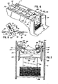
front stops 228,side joggers 230 and backjoggers 232. The front stops 228 are affixed to afront frame mount 234 which is attached to theframe 11 bybolts 236. In addition to confining the movement of the falling sheets, theside joggers 230 and theback joggers 232 neatly position the sheets on the receiving means 226. The joggers oscillate by means well known to those of skill in the art from motion of themain drive shaft 34 transferred to the joggers by a belt and pulley system. In the embodiment shown in Figure 2B, which does not show the duplicative jogging means on the other side of the apparatus,belts 238 operatively engaged to themain drive shaft 34 by pulleys 240 (Fig. 4) rotate the eccentricallymounted shafts 242 about theaxles 244 creating unison movement in thefollowers 246 pivotally connected to one end of therods 248 by thepins 250. Therods 248 linearly reciprocate within cylindrical guides 252 (Fig. 2B) similarly creating reciprocal movement in theback joggers 232 which are affixed to therods 248. The opposite end of therods 248 are pivotally attached to thearms 253 bypivots 254. Theside joggers 230 are interconnected to thearm 253 bybrackts 257. Additional jogging support means 259 aid in the movement of the side joggers 230. Accordingly, linear movement of therods 248 is translated through thearms 253 to oscillate the side joggers 230. Thebelt 238 is tensioned by means of apulley 239 rotatably attached to one end of atensioning bracket 241 by apin 243. Thepulley 239 is adjustably positionable by pivotal movement of thebracket 241 about apin 245 fixably attached to theframe 11. Anarcuate slot 247 at the opposite end ofbracket 241 through which extends a threadedlug 249, fixably attached to theframe 11, limits movement of thebracket 241. Alug nut 251 receptively engages thelug 249 and locks thetensioning bracket 241 in position. - The receiving means 226 has two internally threaded
bores 272 which receptively engage two threadedshafts 274. Each threadedshaft 274 is securely mounted to theframe 11 bybrackets shafts 274 to rotate therein. A pair ofpulleys 278 are attached to the base of the shafts slightly above thebase frame brackets 277. A reversible,variable speed motor 280 vertically translates the position of the receiving means 226 by means of anoutput shaft 282 with apulley 284 affixed thereon and abelt 286 interconnecting thepulleys 278 disposed at the bottom of the twoshafts 274. Themotor 280 is mounted on theframe 11 by a mountingbracket 288 and fourbolts 290. Because the receiving means 226 is cantilevered from the threaded shafts 274 a certain amount of wobbling would occur during movement of the receiving means 226. This problem is avoided byvertical support brackets 292 affixed to the receiving means 226 containing avertical channel 294 for receptively engagingguide bars 296 by bearingelements 298. The guide bars are affixed to theframe 11 and this entire structure provides stability in movement of the receiving means 226. - In its preferred embodiment, the receiving means 226 may be an air table with a grid of
cylindrical bores 260 in which are maintained ball bearings (not shown). Such an air table is of known construction and assembly to those with ordinary skill in the relevant art. Air pressure is supplied to the air table from an air source (not shown) by means of aflexible hose 268 attached to the air source at one end and attached to the air table by apneumatic coupling 270 at the other end. Thus, the ball bearings protrude slightly from thebore 260 due to the supplied air pressure, but as sheets are stacked upon the air table the ball bearings are forced down allowing the air to escape and thereby providing the bottom of the sheet stack with a cushion of air making movement of the stack easier. - The receiving means 226 is limited in movement from a position level with the bottom of the
side joggers 230 to a position level with a stack transport table 300. The stack transport table 300 need only be a large flat surface but in the preferred embodiment of this invention it is an air table of similar construction as described with respect to the sheet receiving means. The stack transport table, however, is fixably mounted to theframe 11. - In the preferred embodiment, a continuous stream of shingled sheets passes through the counter and
stacker system 10. After being counted by the counting means 70, the sheets are transported by a second conveyor 100 and collect on the sheet receiving means 226. As seen more clearly in Figure 5, the receiving means 226 descends at a preselected rate proportional to the rate of the sheets along the conveyors so that the top of the increasingly growing stack is always below the level of the second conveyor system. When a predetermined number of sheets have been counted, the counting means 70 will activate thepiston 166 within thecylinder 168 interconnected to theintermediate deck plate 130 causing theforward nose 224 of theelongated spade 131 to move forward at a rate at least equal to the rate of the sheets on the second - conveyor 100. Thespade 131 will easily slide into the pocket formed by the trailing edge of the last sheet to snap down over theforward nose 224 and the next succeeding sheet still supported by theforward nose 224. A limit switch (not shown) stops the extension of thedeck plate 130 with theforward nose 224 passing between the twofront plates 228. At this point, thedeck plate 130 acts as a temporary receiving means for the still continuing stream of shingled sheets. As seen in-Figure 7, the sheets overlap thedeck plate 130 but do not contact any of the jogging means. This prevents any fouling of the system during the simultaneous stacking of the completed stack. - The
entire deck plate 130 then descends at a rate faster than the descending receiving means 226. This allows the top of the newly forming stack on thespade 131 to be lower than the incoming sheets and further allows thedeck plate 130 to compress the stack of sheets on the slower descending receiving means 226 thereby removing any air in the completed stack for subsequent bundling. Air trapped within the sheets can add several inches or more to the overall height of a stack of sheets depending upon the weight of the paper used and the height of the stack. When heavier stock paper is used, less air is trapped during stacking thereby alleviating the necessity of compressing the stack. In such a circumstance, the timing of the movement of the receiving means 226 relative to thedeck plate 130 can be adjusted. - When the
deck plate 130 has descended into therecess 312 of a plunger 314 (Figs. 1 and 7), a limit switch (not shown) halts any further downward movement. The receiving means 226 continues descending until it stops slightly above the stack transport table 300. The completed stack is pushed onto stack transport table 300 by theplunger 314 which is caused to move by apiston arm 316 interconnected to a piston-cylinder structure 320 (Figs. 1, 2B, 5, 7). The piston-cylinder structure 320 can be activated by the optical counter or by the movement of the receiving means 226 ordeck plate 130. The cylinder is mounted to frame 11 bybrackets - After the completed stack has been moved to the stack transport table 300 and the
plunger 314 has retracted to its original position, the receiving means 226 ascends to a position just below the now stationary and fullyextended spade 131. Thespade 131 is then retracted by its controlling piston-cylinder structure 168 causing the sheets to drop onto the sheet receiving means 226. Additionally, the preferred embodiment includes a pair ofback plates 326 mounted to frame 11 to aid in stripping the newly forming stack of sheets from thespade 131 causing the sheets to drop onto the receiving means 226. Thedeck plate 130 and piston-cylinder structure 168 then ascend to realign thespade 131 between theside plates 132. - While the above description only shows one embodiment of the invention, one will understand, of course, that the invention is not limited thereto since one may make modifications, and other embodiments of the principles of this invention will occur to those skilled in the art to which the invention pertains, particularly upon considering the foregoing teachings. For example, those skilled in the art will appreciate that one may run the stacker without the optical counting means operating. The counting means may either be switched off electrically or the
frame 78 may be positioned perpendicular to the stream of sheets so that the trailing edges of the individual sheets are not caused to flip down and interrupt the photoelectric beam. Additionally, the counting means may be relocated to a position within the folding operation but still used to control the movement of thespade 131 during stacking. - Also, to aid in the formation of the pocket into which the spade 13I extends, it is possible to add a narrow impinging roller or other type of deflection means disposed forward of the
nose 224 while in its refracted position and along the centerline of the sheets. This roller will be spring loaded downwardly from a member traversing theframe 11 and have its "at rest" position lower than the surface of thespade 131. Thus, as the sheets are still supported by theside deck plates 132 and last dual pair ofrollers - Moreover, it is contemplated that the present embodiment could also be used with a second conveyor that transports the sheets in a substantially flat relaticnship rather then bowed as in the preferred embodiment. The additional impinging roller, rather than helping form a pocket for insertion of the
spade 131, will cause the entire trailing edge of each succeeding flat sheet to flip down off the conveyor while still securely positioned by the last dual pair ofrollers - It is therefore contemplated by the appended claims to cover any such modification and other embodiments as incorporate those features which constitute the essential features of this invention within the true spirit and scope of the following claims. What is claimed is:
Claims (8)
1. A system for stacking a stream of shingled shee@s, comprising a conveyor means for receiving said shingled sheets, means for successively counting the individual sheets, means responsive to said counting means for inserting into said stream of shingled sheets in the direction of movement of said sheets and separating the stream of shingled sheets at a predetermined location in the stream upon said counting means reaching a predetermined count, and a stacking means for receiving and stacking the separated, shingled sheets.
2. A system for stacking a stream of shingled sheets according to claim 1, wherein sald insertion means is a spade positioned along the direction of travel of said stream of shingled sheets and below the sheets and having a forward end positioned upstream of said stacking means, the system further including means for causing the tail of each of the shingled sheets to separate from the next successive sheet in front of the forward end of the spade.
3. A system for stacking a stream of shingled sheets according to claim 1, further including a second conveyor means positioned between said counting means and said stacking means for conveying the stream of sheets from said counting means to said stacking means, the insertion means being positioned at or below said second conveyor means along the direction of travel of said stream of shingled sheets.
4. A system for stacking a stream of shingled sheets according to claim 3, wherein said insertion means is operatively associated with said second conveyor means to form at least a partial support for sheets being conveyed along said second conveyor means.
5. A system for stacking a stream of shingled sheets according to claim 3, wherein said second conveyor means is concavely formed along its transverse cross- section for imparting an inwardly directed bow to sheets being conveyed thereon.
6. A system for stacking a stream of shingled sheets according to claim 1, wherein said stacking means includes means vertically adjustable for receiving said sheets one at a time exiting said conveyor, means for aligning said individual sheets on said receiving means, and means for removing said separated and stacked sheets from said receiving means.
7. A system for counting a stream of shingled sheets, comprising, a first conveyor means aligned and in planar relationship with a second conveyor means, a photoelectric transmitter and receiver subtending said conveyors, means disposed between said first and second conveyor means causing the leading edge of each succeeding sheet to be forced upwardly thereby causing each succeeding trailing edge of said sheets to be forced downwardly whereby the light beam traveling between said photoelectric transmitter and receiver is interrupted causing said sheets to be individually counted.
8. The process of stacking a stream of sheets in pre-selected quantities wherein a continuous flow of substantially flat sheets are shingled for unison movement by the leading edge of each sheet overlying the trailing edge of the preceding sheet; said shingled sheets being first received by a first conveyor means and transported for a distance; said sheets then exiting said first conveyor and being caused to travel through an optical counting means wherein the individual sheets are counted; said sheets then entering a second conveyor means also having an exiting end which second conveyor means imparts a transverse bow upon said sheets; said second conveyor means having an insertion means with a forward nose disposed beneath and at the exit end of said second conveyor; said bowed sheets being caused to travel over said forward nose of said insertion means with said trailing edges of said sheets being caused to snap downwardly past said nose of said insertion means; said sheets exiting said second conveyor are then collected on a receiving means; said preselected quantity of said sheets having passed said counting means, said insertion means is activated by said optical counting means and caused to extend in the direction of sheet flow, separating said sheets thereby defining a completed stack of sheets and a newly forming stack of sheets: said completed stack of sheets is caused to be removed from said insertion means retracting to its original position whereby said newly forming stack of sheets is transferred to said receiving means.
Applications Claiming Priority (2)
| Application Number | Priority Date | Filing Date | Title |
|---|---|---|---|
| US06/704,676 US4652197A (en) | 1985-02-22 | 1985-02-22 | Sheet counter and stacker system |
| US704676 | 1985-02-22 |
Publications (2)
| Publication Number | Publication Date |
|---|---|
| EP0192211A2 true EP0192211A2 (en) | 1986-08-27 |
| EP0192211A3 EP0192211A3 (en) | 1987-06-16 |
Family
ID=24830451
Family Applications (1)
| Application Number | Title | Priority Date | Filing Date |
|---|---|---|---|
| EP86101941A Withdrawn EP0192211A3 (en) | 1985-02-22 | 1986-02-15 | Sheet counter and stacker system |
Country Status (2)
| Country | Link |
|---|---|
| US (1) | US4652197A (en) |
| EP (1) | EP0192211A3 (en) |
Cited By (2)
| Publication number | Priority date | Publication date | Assignee | Title |
|---|---|---|---|---|
| WO1999000305A1 (en) * | 1997-06-26 | 1999-01-07 | Bobst Group, Inc. | Combination counter-ejector shingle-output delivery system |
| WO2009025612A1 (en) | 2007-08-20 | 2009-02-26 | Lasermax Roll Systems Ab | Arrangement for stacking sheets |
Families Citing this family (12)
| Publication number | Priority date | Publication date | Assignee | Title |
|---|---|---|---|---|
| US4911421A (en) * | 1986-03-21 | 1990-03-27 | Stepper, Inc. | Newspaper handling and collating method and apparatus |
| US4934687A (en) * | 1988-01-11 | 1990-06-19 | Galpin Research, Limited Partnership | High speed stream fed stacker method and system for printed products |
| EP0346124B2 (en) * | 1988-06-09 | 1998-05-06 | Kabushiki Kaisha Toshiba | Compound superconducting wire and method of manufacturing the same |
| DE58904720D1 (en) * | 1988-11-11 | 1993-07-22 | Ferag Ag | METHOD AND DEVICE FOR CONVEYING PRINTING PRODUCTS. |
| US5026249A (en) * | 1989-05-26 | 1991-06-25 | Thermoguard Equipment, Inc. | Apparatus for stacking corrugated sheet material |
| DE59002531D1 (en) * | 1989-06-23 | 1993-10-07 | Ferag Ag | Device for stacking printed products in a shingled stream. |
| IT1246101B (en) * | 1991-05-17 | 1994-11-14 | Gd Spa | DEVICE FOR COMPACTION OF STACKED STACKS AND CORRECTION OF THEIR POSITION ON RESPECTIVE SUPPLY BODIES. |
| EP1044429B1 (en) * | 1997-12-30 | 2002-08-07 | Ferag AG | Device for counting products conveyed as an overlapping arrangement |
| US6808361B1 (en) | 2002-03-27 | 2004-10-26 | John T. McCarthy | Apparatus and method for stacking food portions |
| US7416073B1 (en) * | 2007-02-09 | 2008-08-26 | Geo. M. Martin Company | Diverting flat belt support system |
| JP5472777B2 (en) * | 2008-05-28 | 2014-04-16 | レンゴー株式会社 | Single-sided cardboard sheet stacking device |
| US20180229871A1 (en) * | 2015-06-30 | 2018-08-16 | Kimberly-Clark Worldwide, Inc. | Tissue packaging apparatus |
Citations (5)
| Publication number | Priority date | Publication date | Assignee | Title |
|---|---|---|---|---|
| FR1143623A (en) * | 1955-05-27 | 1957-10-03 | Igranic Electric Co Ltd | Method and devices for counting and stacking newspapers and articles of similar shape |
| FR1547603A (en) * | 1966-09-30 | 1968-11-29 | Ferag Ag | Installation to count advancing staggered products |
| US3756591A (en) * | 1971-08-10 | 1973-09-04 | H Muller | Apparatus for stacking sheets |
| DE2725267B1 (en) * | 1977-06-03 | 1978-11-09 | Bielomatik Leuze & Co | Stacking device for storing sheets |
| EP0128873A2 (en) * | 1983-06-14 | 1984-12-19 | CIVIEMME S.r.l. | Signature stacking machine |
Family Cites Families (28)
| Publication number | Priority date | Publication date | Assignee | Title |
|---|---|---|---|---|
| US2205767A (en) * | 1938-07-05 | 1940-06-25 | George E Lamb | Continuous layboy |
| US2708863A (en) * | 1951-07-03 | 1955-05-24 | American Colortype Company | Stacking conveyor for books and the like |
| US2787363A (en) * | 1953-11-05 | 1957-04-02 | Cutler Hammer Inc | Apparatus for handling sheet-like articles |
| US2853299A (en) * | 1954-04-05 | 1958-09-23 | Kimberly Clark Co | Layboy |
| US3096978A (en) * | 1959-08-20 | 1963-07-09 | Will E C H | Device for overlapping sheets of paper, press board and other material |
| US3054516A (en) * | 1960-08-19 | 1962-09-18 | Joa Curt George | Apparatus for stacking sheets |
| US3169646A (en) * | 1961-08-18 | 1965-02-16 | Fryer Corp | Lumber stacker |
| DE1235808B (en) * | 1963-04-27 | 1967-03-02 | Schiepe Holzbearbeitungsmasch | Stacking device for stab- and board-shaped items, especially for profile strips |
| US3362707A (en) * | 1964-11-27 | 1968-01-09 | Ahlstroem Oy | Auxiliary stack holder |
| US3529168A (en) * | 1967-02-23 | 1970-09-15 | Graphicart Int | Automatic device for counting folded papersheets or printed matters,especially folded newspapers which are conveyed in shingled manner on a conveyorband |
| CH457268A (en) * | 1967-05-26 | 1968-05-31 | Ferag Ag | Device for depositing flat objects in a stack |
| US3543651A (en) * | 1968-08-16 | 1970-12-01 | Graphic Engineers Inc | Machine for stacking papers into stacks of predetermined count |
| US3599805A (en) * | 1969-06-03 | 1971-08-17 | Paper Converting Machine Co | Unit-handling apparatus |
| US3568578A (en) * | 1969-07-10 | 1971-03-09 | Yuji Fujishiro | Counter stacker of the rolling press |
| US3566757A (en) * | 1969-07-23 | 1971-03-02 | Yuji Fujishiro | Apparatus for making bundles from the stream of printed sheets in rolling press |
| DE2003553A1 (en) * | 1970-01-27 | 1971-08-05 | Windmoeller & Hoelscher | Device for the continuous formation of packets of workpieces with the same edges from a series of workpieces that overlap in a scale-like manner, in particular sacks and bags |
| US3737666A (en) * | 1971-04-15 | 1973-06-05 | L Dutro | Counter for a stream of overlapped articles |
| US3785256A (en) * | 1971-09-29 | 1974-01-15 | Westvaco Corp | Panel counting, collecting and gating apparatus |
| US3834289A (en) * | 1973-04-02 | 1974-09-10 | Graphic Engineers Inc | Photoelectric counter for paper conveyor |
| US4006831A (en) * | 1974-03-06 | 1977-02-08 | Electra Food Machinery, Inc. | Automatic tortilla counter and stacker |
| US3887013A (en) * | 1974-06-24 | 1975-06-03 | Tri County Machine Products In | Sod cutting and stacking machine |
| US3948153A (en) * | 1974-07-12 | 1976-04-06 | Mildred L. Taylor | Count separator for a stream of overlapped articles |
| GB1581544A (en) * | 1976-06-29 | 1980-12-17 | Masson Scott Thrissell Eng Ltd | Sheet stacking apparatus |
| US4189133A (en) * | 1978-11-03 | 1980-02-19 | International Business Machines Corporation | Document stacking table lowering method, apparatus and controlling circuitry therefor |
| JPS5585988A (en) * | 1978-12-22 | 1980-06-28 | Laurel Bank Mach Co Ltd | Paper pile counter for different type note discrimination |
| US4359218A (en) * | 1980-06-23 | 1982-11-16 | Beloit Corporation | Continuous sheet collection and discharge system |
| CH652840A5 (en) * | 1981-08-11 | 1985-11-29 | Grapha Holding Ag | DEVICE FOR NUMBERING THE PRINTED SHEETS OF A DOMESTIC CURRENT. |
| JPS5854490A (en) * | 1981-09-28 | 1983-03-31 | Tokyo Kikai Seisakusho:Kk | Counter of printed matter |
-
1985
- 1985-02-22 US US06/704,676 patent/US4652197A/en not_active Expired - Fee Related
-
1986
- 1986-02-15 EP EP86101941A patent/EP0192211A3/en not_active Withdrawn
Patent Citations (5)
| Publication number | Priority date | Publication date | Assignee | Title |
|---|---|---|---|---|
| FR1143623A (en) * | 1955-05-27 | 1957-10-03 | Igranic Electric Co Ltd | Method and devices for counting and stacking newspapers and articles of similar shape |
| FR1547603A (en) * | 1966-09-30 | 1968-11-29 | Ferag Ag | Installation to count advancing staggered products |
| US3756591A (en) * | 1971-08-10 | 1973-09-04 | H Muller | Apparatus for stacking sheets |
| DE2725267B1 (en) * | 1977-06-03 | 1978-11-09 | Bielomatik Leuze & Co | Stacking device for storing sheets |
| EP0128873A2 (en) * | 1983-06-14 | 1984-12-19 | CIVIEMME S.r.l. | Signature stacking machine |
Cited By (3)
| Publication number | Priority date | Publication date | Assignee | Title |
|---|---|---|---|---|
| WO1999000305A1 (en) * | 1997-06-26 | 1999-01-07 | Bobst Group, Inc. | Combination counter-ejector shingle-output delivery system |
| WO2009025612A1 (en) | 2007-08-20 | 2009-02-26 | Lasermax Roll Systems Ab | Arrangement for stacking sheets |
| US8141869B2 (en) | 2007-08-20 | 2012-03-27 | Lasermax Roll Systems Ab | Arrangement for stacking sheets |
Also Published As
| Publication number | Publication date |
|---|---|
| EP0192211A3 (en) | 1987-06-16 |
| US4652197A (en) | 1987-03-24 |
Similar Documents
| Publication | Publication Date | Title |
|---|---|---|
| US4652197A (en) | Sheet counter and stacker system | |
| US4616815A (en) | Automatic stacking and folding apparatus | |
| EP0455494A2 (en) | Dual collating machine | |
| US2853298A (en) | Jogger mechanisms | |
| US5033729A (en) | Mechanism for the handling and singulating of flat materials | |
| US4330116A (en) | Bundling mechanism for signatures | |
| CA1330219C (en) | Method and apparatus for feeding carton blanks | |
| EP0033835A1 (en) | Sheet stack aligner | |
| US4372201A (en) | Device for producing a bundle of paper sheets | |
| GB2261872A (en) | Buckle chute folder. | |
| US4541764A (en) | Document stacking and conveying apparatus | |
| GB1561761A (en) | Sheet feeding | |
| US4311090A (en) | Method producing a bundle of paper sheets | |
| US6120239A (en) | Compensating stacking machine and method of using same | |
| US3871644A (en) | Sheet stacker with jogger | |
| CN109436912B (en) | Quick collecting, arranging and transferring mechanism for sheet printing stock and packing and stacking device thereof | |
| US4886265A (en) | Apparatus and method for stacking printed products, especially printed products arriving in an imbricated formation | |
| US3266799A (en) | Stacking apparatus having yieldable feed means | |
| WO1992006031A1 (en) | Article stopping apparatus | |
| US3595568A (en) | Jogger stacker machine | |
| EP0070792A1 (en) | Integral paper collection and transfer assembly | |
| SE431081B (en) | Method and apparatus for sizing documents on a continuous support web | |
| US4249844A (en) | Apparatus for accumulating stacks of note books or the like | |
| EP0768260B1 (en) | Paper handling apparatus | |
| EP0376507B1 (en) | Power stacking apparatus |
Legal Events
| Date | Code | Title | Description |
|---|---|---|---|
| PUAI | Public reference made under article 153(3) epc to a published international application that has entered the european phase |
Free format text: ORIGINAL CODE: 0009012 |
|
| AK | Designated contracting states |
Kind code of ref document: A2 Designated state(s): DE FR GB |
|
| PUAL | Search report despatched |
Free format text: ORIGINAL CODE: 0009013 |
|
| AK | Designated contracting states |
Kind code of ref document: A3 Designated state(s): DE FR GB |
|
| STAA | Information on the status of an ep patent application or granted ep patent |
Free format text: STATUS: THE APPLICATION IS DEEMED TO BE WITHDRAWN |
|
| 18D | Application deemed to be withdrawn |
Effective date: 19871217 |
|
| RIN1 | Information on inventor provided before grant (corrected) |
Inventor name: LITTLETON, FRANCIS JOHN |