EP0191844B1 - Filtre a cartouche unique - Google Patents
Filtre a cartouche unique Download PDFInfo
- Publication number
- EP0191844B1 EP0191844B1 EP85904374A EP85904374A EP0191844B1 EP 0191844 B1 EP0191844 B1 EP 0191844B1 EP 85904374 A EP85904374 A EP 85904374A EP 85904374 A EP85904374 A EP 85904374A EP 0191844 B1 EP0191844 B1 EP 0191844B1
- Authority
- EP
- European Patent Office
- Prior art keywords
- partition
- vessel
- annular
- filter cartridge
- cover
- Prior art date
- Legal status (The legal status is an assumption and is not a legal conclusion. Google has not performed a legal analysis and makes no representation as to the accuracy of the status listed.)
- Expired - Lifetime
Links
- 238000005192 partition Methods 0.000 claims abstract description 60
- 239000007788 liquid Substances 0.000 claims abstract description 35
- 229920001944 Plastisol Polymers 0.000 claims abstract description 27
- 239000004999 plastisol Substances 0.000 claims abstract description 27
- 229920003023 plastic Polymers 0.000 claims description 31
- 239000004033 plastic Substances 0.000 claims description 31
- 239000000463 material Substances 0.000 claims description 11
- 238000007789 sealing Methods 0.000 claims description 11
- 210000002445 nipple Anatomy 0.000 claims description 10
- 238000012360 testing method Methods 0.000 claims description 9
- 230000002093 peripheral effect Effects 0.000 claims description 6
- 125000006850 spacer group Chemical group 0.000 claims description 5
- 230000006872 improvement Effects 0.000 claims description 4
- 229910001220 stainless steel Inorganic materials 0.000 claims description 2
- 239000010935 stainless steel Substances 0.000 claims description 2
- 239000012530 fluid Substances 0.000 claims 2
- 239000007789 gas Substances 0.000 abstract description 7
- 238000010276 construction Methods 0.000 abstract 1
- 235000019589 hardness Nutrition 0.000 description 11
- 229920000915 polyvinyl chloride Polymers 0.000 description 5
- 239000004800 polyvinyl chloride Substances 0.000 description 5
- 230000008901 benefit Effects 0.000 description 4
- 239000000853 adhesive Substances 0.000 description 2
- 230000001070 adhesive effect Effects 0.000 description 2
- 239000003054 catalyst Substances 0.000 description 2
- 229920001971 elastomer Polymers 0.000 description 2
- 238000001914 filtration Methods 0.000 description 2
- 239000002184 metal Substances 0.000 description 2
- 125000002524 organometallic group Chemical group 0.000 description 2
- 239000000049 pigment Substances 0.000 description 2
- 239000004014 plasticizer Substances 0.000 description 2
- 239000003381 stabilizer Substances 0.000 description 2
- 238000007655 standard test method Methods 0.000 description 2
- XLYOFNOQVPJJNP-UHFFFAOYSA-N water Substances O XLYOFNOQVPJJNP-UHFFFAOYSA-N 0.000 description 2
- NIXOWILDQLNWCW-UHFFFAOYSA-M Acrylate Chemical compound [O-]C(=O)C=C NIXOWILDQLNWCW-UHFFFAOYSA-M 0.000 description 1
- 241001050985 Disco Species 0.000 description 1
- 239000004593 Epoxy Substances 0.000 description 1
- 229910000760 Hardened steel Inorganic materials 0.000 description 1
- 239000004743 Polypropylene Substances 0.000 description 1
- 238000009825 accumulation Methods 0.000 description 1
- 230000009471 action Effects 0.000 description 1
- 230000008859 change Effects 0.000 description 1
- 239000002826 coolant Substances 0.000 description 1
- 238000005260 corrosion Methods 0.000 description 1
- 230000007797 corrosion Effects 0.000 description 1
- 239000002537 cosmetic Substances 0.000 description 1
- 230000008878 coupling Effects 0.000 description 1
- 238000010168 coupling process Methods 0.000 description 1
- 238000005859 coupling reaction Methods 0.000 description 1
- 239000004744 fabric Substances 0.000 description 1
- 239000004615 ingredient Substances 0.000 description 1
- 235000021056 liquid food Nutrition 0.000 description 1
- 238000005259 measurement Methods 0.000 description 1
- 239000000203 mixture Substances 0.000 description 1
- 239000000178 monomer Substances 0.000 description 1
- 150000002978 peroxides Chemical class 0.000 description 1
- 239000002985 plastic film Substances 0.000 description 1
- -1 polypropylene Polymers 0.000 description 1
- 229920001155 polypropylene Polymers 0.000 description 1
- 229920002635 polyurethane Polymers 0.000 description 1
- 239000004814 polyurethane Substances 0.000 description 1
- 238000006748 scratching Methods 0.000 description 1
- 230000002393 scratching effect Effects 0.000 description 1
- 239000000126 substance Substances 0.000 description 1
- 230000009182 swimming Effects 0.000 description 1
- 238000003466 welding Methods 0.000 description 1
Images

Classifications
-
- B—PERFORMING OPERATIONS; TRANSPORTING
- B01—PHYSICAL OR CHEMICAL PROCESSES OR APPARATUS IN GENERAL
- B01D—SEPARATION
- B01D35/00—Filtering devices having features not specifically covered by groups B01D24/00 - B01D33/00, or for applications not specifically covered by groups B01D24/00 - B01D33/00; Auxiliary devices for filtration; Filter housing constructions
- B01D35/30—Filter housing constructions
-
- B—PERFORMING OPERATIONS; TRANSPORTING
- B01—PHYSICAL OR CHEMICAL PROCESSES OR APPARATUS IN GENERAL
- B01D—SEPARATION
- B01D29/00—Filters with filtering elements stationary during filtration, e.g. pressure or suction filters, not covered by groups B01D24/00 - B01D27/00; Filtering elements therefor
- B01D29/11—Filters with filtering elements stationary during filtration, e.g. pressure or suction filters, not covered by groups B01D24/00 - B01D27/00; Filtering elements therefor with bag, cage, hose, tube, sleeve or like filtering elements
- B01D29/13—Supported filter elements
- B01D29/15—Supported filter elements arranged for inward flow filtration
- B01D29/21—Supported filter elements arranged for inward flow filtration with corrugated, folded or wound sheets
-
- B—PERFORMING OPERATIONS; TRANSPORTING
- B01—PHYSICAL OR CHEMICAL PROCESSES OR APPARATUS IN GENERAL
- B01D—SEPARATION
- B01D29/00—Filters with filtering elements stationary during filtration, e.g. pressure or suction filters, not covered by groups B01D24/00 - B01D27/00; Filtering elements therefor
- B01D29/60—Filters with filtering elements stationary during filtration, e.g. pressure or suction filters, not covered by groups B01D24/00 - B01D27/00; Filtering elements therefor integrally combined with devices for controlling the filtration
- B01D29/605—Filters with filtering elements stationary during filtration, e.g. pressure or suction filters, not covered by groups B01D24/00 - B01D27/00; Filtering elements therefor integrally combined with devices for controlling the filtration by level measuring
-
- B—PERFORMING OPERATIONS; TRANSPORTING
- B01—PHYSICAL OR CHEMICAL PROCESSES OR APPARATUS IN GENERAL
- B01D—SEPARATION
- B01D29/00—Filters with filtering elements stationary during filtration, e.g. pressure or suction filters, not covered by groups B01D24/00 - B01D27/00; Filtering elements therefor
- B01D29/88—Filters with filtering elements stationary during filtration, e.g. pressure or suction filters, not covered by groups B01D24/00 - B01D27/00; Filtering elements therefor having feed or discharge devices
- B01D29/92—Filters with filtering elements stationary during filtration, e.g. pressure or suction filters, not covered by groups B01D24/00 - B01D27/00; Filtering elements therefor having feed or discharge devices for discharging filtrate
- B01D29/925—Filters with filtering elements stationary during filtration, e.g. pressure or suction filters, not covered by groups B01D24/00 - B01D27/00; Filtering elements therefor having feed or discharge devices for discharging filtrate containing liquid displacement elements or cores
-
- B—PERFORMING OPERATIONS; TRANSPORTING
- B01—PHYSICAL OR CHEMICAL PROCESSES OR APPARATUS IN GENERAL
- B01D—SEPARATION
- B01D29/00—Filters with filtering elements stationary during filtration, e.g. pressure or suction filters, not covered by groups B01D24/00 - B01D27/00; Filtering elements therefor
- B01D29/96—Filters with filtering elements stationary during filtration, e.g. pressure or suction filters, not covered by groups B01D24/00 - B01D27/00; Filtering elements therefor in which the filtering elements are moved between filtering operations; Particular measures for removing or replacing the filtering elements; Transport systems for filters
-
- B—PERFORMING OPERATIONS; TRANSPORTING
- B01—PHYSICAL OR CHEMICAL PROCESSES OR APPARATUS IN GENERAL
- B01D—SEPARATION
- B01D2201/00—Details relating to filtering apparatus
- B01D2201/30—Filter housing constructions
- B01D2201/301—Details of removable closures, lids, caps, filter heads
-
- B—PERFORMING OPERATIONS; TRANSPORTING
- B01—PHYSICAL OR CHEMICAL PROCESSES OR APPARATUS IN GENERAL
- B01D—SEPARATION
- B01D2201/00—Details relating to filtering apparatus
- B01D2201/30—Filter housing constructions
- B01D2201/301—Details of removable closures, lids, caps, filter heads
- B01D2201/304—Seals or gaskets
-
- B—PERFORMING OPERATIONS; TRANSPORTING
- B01—PHYSICAL OR CHEMICAL PROCESSES OR APPARATUS IN GENERAL
- B01D—SEPARATION
- B01D2201/00—Details relating to filtering apparatus
- B01D2201/31—Other construction details
- B01D2201/316—Standpipes
Definitions
- the single cartridge filter of this invention comprises a vessel with an open top into which the improved single filter cartridge of this invention is easily placed and removed.
- An easily removable domed cover for the open top of the vessel clamps between its periphery and the rim of the vessel, a flexible partition plate separating the vessel into two chambers, one for dirty liquid below the partition and one for clean or filtered liquid above the partition.
- the peripheral edge of the partition has a gasket which extends over both sides thereof for sealing the partition plate in the vessel and the cover on the vessel.
- the inlet and outlet are in the vessel housing, the outlet being directly connected to a vertical tube which extends up through the vessel through an aperture in the partition plate to above the rim of the vessel into the clean liquid chamber.
- the partition plate is provided with spacer means which engage the inside of the dome of the cover for limiting the flexing of the partition when the cover is clamped onto the vessel. If desired, and preferably, the partition plate is grounded by means of a scratch-contact as disclosed in applicant's above mentioned Harms U.S. Patent No. 4,187,179.
- An important improvement of this invention is in the single filter cartridge which comprises a cylindrical pleated fibrous sheet filter medium, surrounding a perforated tube having a larger inside diameter than the outside diameter of the vertical outlet duct up through the inside of the vessel, over and spaced around which duct the cartridge is placed.
- Annular plastisol discs close the ends of the pleats at the opposite ends of the filter cartridge and seal with the bottom side of the partition and with the outside of the lower end of the outlet tube.
- These plastisol discs are press-sealed at one or both ends and may include integral softer plastisol rings to form gaskets that seal around the bottom of the vertical outlet duct near the bottom of the filter vessel and seal with the underside of the flexible partition plate at the top of the filter vessel.
- the clamping action may be by pressure of the cover against the spacers on the partition, or by a nipple which threads into one end of the cartridge and extends through the aperture in the partition to receive a ring nut thereon to clamp the cartridge to the partition.
- the aperture in the partition plate for the vertical outlet duct or tube is sufficiently larger in diameter than the outside diameter of the outlet tube and the inside diameter of the threaded nipple, so as to provide an annular opening for the filtered liquid from the perforated center tube of the cartridge to flow freely into the dome-covered clean liquid chamber above the partition.
- dirty liquid to be filtered is introduced into the vessel, preferably at its bottom, and flows around the outside of the single filter cartridge.
- the filtered liquid passes through the perforations in the central tube of the cartridge, around the outside of the vertical outlet duct up into the domed cover of the vessel, and thence down through said vertical outlet duct. Accordingly, any air or gas that would accumulate in the vessel or its cover will be sucked out automatically through the outlet duct by the liquid flow, and any dirt that would accumulate on the filter cartridge which would fall off, will fall into the dirty liquid, and not come in contact with any of the clean or filtered liquid in the cover of the vessel.
- the single filter cartridge of this invention can be used generally for filtering many types of liquids in a closed vessel to which a different pressure than atmospheric pressure is applied, usually an increased pressure.
- some of the liquids which can be filtered include contaminated water, including water from swimming pools, chemicals, cosmetics, industrial coolants, liquid foods, etc.
- Another object is to produce such a filter housing which contains a partition that separates the dirty from the clean liquid.
- a further object is to produce such a filter which has an easily and quickly replaceable single filter cartridge provided with integral sealing gaskets.
- a still further object is to produce such a liquid filter which automatically removes any gases that may be introduced into the filter vessel.
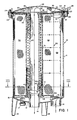
- the single cartridge filter assembly 10 of this invention comprises an open top vertical cylindrical container or vessel 11, whose closed bottom 12 may be supported by at least three equally spaced legs 13 to provide room for easy connection to inlet duct 14 which may be covered by a baffle 15, and outlet duct 16 through the bottom 12 as well as a drain duct 18 provided with a screw cap 17. All of these ducts 14, 16 and 18 are preferably hermetically joined, such as by welding, to the bottom 12 of the metal container or vessel 11, and may have their outer ends threaded for connection to pipes.
- the legs 13 also may be welded to the bottom 12.
- the top of the vessel 11 may be provided adjacent the rim 19 with an outwardly extending circumferential rib 21 to which are welded a plurality of equally angularly spaced upwardly extending threaded studs 22.
- the open top of the vessel 11 is closed by a domed cover 20 having an outwardly extending peripheral flange 23 with apertures 24 which align with the threaded studs 22, onto which studs are threaded winged nuts 25 for clamping the cover 20 onto the vessel 11.
- a vertical imperforate outlet tube 40 is sealingly attached at its lower end by a sleeve 41 to the outlet duct 16 to form an extension of this outlet duct 16 up through the perforated tube 51 centrally of the cartridge filter 50 and through the center of the aperture 32 in the partition 30 and on to above the rim 19 of the vessel 11 into the upper filtered or clean liquid chamber 28 in the. domed cover.
- This surrounding sleeve 41 may be sealed to these ducts 16 and 40 by threads and/or a suitable adhesive.
- a flexible partition plate 30 Inside the vessel 11 and clamped between the cover 20 and the upper peripheral edge or rim 19 of the vessel 11 is a flexible partition plate 30 around the peripheral edge of which is a gasket 31 having a U-shaped cross-section, or a circular cross-section with a radial slit, for seating and surrounding the outer edge of plate 30 by overlapping opposite sides of its edge.
- this gasket 31 seals the edge of the dome of the cover 20 to the upper rim 19 of the vessel 11 as well as the partition 30 to form two separate compartments or chambers 28 and 58 in the domed cover 20 and the vessel 11, respectively, when the winged nuts 25 are all tightened on their studs 22.
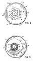
- the flexible partition plate 30 is provided with an aperture 32 vertically aligned with the outlet duct 16 and through the center of which aperture extends an imperforate vertical outlet tube 40 to form an annular opening 38 for the free flow of filtered liquid into the clean liquid chamber 28. If desired, as shown in Figs. 1 and 2, this aperture 32 may be surrounded by inwardly radially extending flexible clips 33 for centering the vertical imperforate outlet tube or duct 40 in the aperture 32 to insure the annular passage 38.
- This partition plate 30 also may be preferably provided with a scratching resilient grounding contact 34 as disclosed and described in applicant's above mentioned U.S. Patent No. 4,187,179.
- the partition plate 30 is provided with spacing means between its upper surface and the inner surface of the domed cover 20.
- this spacing means is shown to comprise a plurality of equally angularly spaced upwardly extending legs or brackets 35 of inverted U-shaped configuration, which not only limits the upward flexing of the partition plate 30, but also may extend up further than the normal distance of the height of the inside of the dome of the cover 20 so that when the cover 20 is clamped in position, these legs 35 will press and bend the plate 30 downwardly to sealingly contact the upper resilient surface of disc 53 of the single filter cartridge 50, and/or gasket 56 (See Figs. 4 and 7).
- this spacing means is shown to comprise a plurality of equally angularly spaced upwardly extending legs or brackets 35 of inverted U-shaped configuration, which not only limits the upward flexing of the partition plate 30, but also may extend up further than the normal distance of the height of the inside of the dome of the cover 20 so that when the cover 20 is clamped in position, these legs 35 will press and bend the
- this spacer means is shown to comprise a circular fence 36 which may only limit the flexing of the partition 30 toward the cover 20 when liquid introduced into the inlet 14 is under a greater pressure than in the outlet 16. This limiting of the flexibility of the partition 30 prevents pulling of the peripheral gasket 31 out from between the rim 19 and flange 23, insuring continuous sealing of the cover 20 on the vessel 11 and of the partition 30 separating the clean liquid compartment 28 from the dirty liquid compartment 58.
- the single filter cartridge 50 which substantially fills the dirty liquid chamber 58 inside the vessel or container 11, comprises a central perforated tube 51 of larger inside diameter than the outside diameter of the outlet tubular duct 40, and has a diameter about equal to, and preferably at least that of, the diameter of the aperture 32 in the partition plate 30.
- a perforated tube 51 Surrounding this perforated tube 51 may be and herein shown a pleated fabric or fibrous sheet medium 52, the open ends of which axially aligned pleats are sealed closed by being embedded in top and bottom resilient plastic annular discos 53 and 54, respectively, together with the ends of the perforated tube 51.
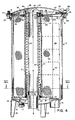
- the sleeve 41 around the lower end of the imperforate outlet tube 40 provides at the upper end 42 of said sleeve 41, a seat for an 0-ring 43 which seals against the inner flange 44 of a surrounding bushing 45 having a lower outwardly extending flange 46 that supports and seals against the resilient surface of the disc 54 at the lower end of the filter cartridge 50.
- the mold for forming the annular end discs 53 and 54 for a pleated filter cartridge 50 may comprise an additional annular groove adjacent the inner diameter of the disc into which is poured a softer plastisol than that normally employed for forming the discs 53 and 54.
- the plastisol normally employed for the end discs 53 and 54 is resilient and can act as a seal if pressed firmly against a cooperating surface, such Gas disc 53 pressed against the underside of partition plate 30 in Fig. 1. It has been found to be advantageous if separate parts as the bushing 44, 45, 46 and O-ring 43 shown in the embodiment of Figs.
- the upper end disc 53 of the single filter cartridge has also therein an internally threaded central aperture 59 with an internal inner flange to receive and seat respectively an externally threaded nipple 60.
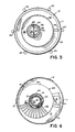
- This nipple 60 projects up through the aperture 32 in the partition 30 and at its exposed threaded outer end has a ring nut 62 with a diametric handle rod 63 manually threaded thereon for clamping the single filter cartridge 50 against the underside of the partition plate 30, preferably against the integral gasket 56 as shown in Fig. 7.
- the partition plate 30 and single filter cartridge 50 may be removed as a unit from the vessel 11 using the rod 63 as a lifting handle, and then the plate can easily be removed from the cartridge or vice versa by unscrewing the ring nut 62 and/or the nipple 60 from the internally threaded 59 upper disc 53 of the filter cartridge 50.
- the nipple 60 may be attached by an adhesive to either the threads 59 or to the nut 62.
- the liquid to be filtered is introduced, usually by a pump (not shown), into the inlet duct 14 and distributed by baffle 15 around the chamber 58 outside of the single filter cartridge 50 in the vessel 11 as shown by the arrows in Figs 1 and 4.
- the dirty liquid passes to the filter medium of the pleats 52 and clean liquid passes from the pleats and through the holes in the apertured central tube 51 up the annular duct and through the annular opening 38 in the partition 30 into the clean liquid cylindrical chamber 28 under the domed cover 20, and then down through the outlet tube 40 and outlet duct 16.
- any gases or air gets into the filter assembly 10, it will tend to accumulate in the chamber 28 under the domed cover 20 where it is automatically removed through the outlet duct tube 40 that extends into this domed chamber 28.
- the single filter cartridge 50 needs to be cleaned or replaced, such can easily be done by removing the wing nuts 25, taking off the cover 20, lifting off the flexible partition 30 by brackets 35 or handle 63 and the single filter cartridge 50 from the outlet duct tube 40.
- the cartridge 50 may be first clamped to the partition 30 by nipple 60 and nut 62, or it may be first placed over the outlet duct tube 40, and then the partition plate 30 placed on the rim 19 of the vessel and around the upper end of the outlet duct 40.
- the filter cartridge 50 is clamped into place by the ring nut 62 according to the embodiment shown in Figs. 4 through 8, or by the wing nuts 25 on the cover 20 after the cover is put in place, according to the embodiment shown in Figs. 1 through 3.
- the changing of the filter cartridge 50 is singular and easy and also has the additional unexpected advantage of having a greater surface area than can be obtained by a plurality of smaller cartridges in an array suspended from a partition plate as disclosed in applicant's above mentioned two prior patents.
- the vessel 11, cover 20, and ducts 14, 16 and 18 are made of metal, preferably stainless steel to avoid corrosion, and the internal outlet tubular duct 40, bushings 41 and 46, filter cartridge central tube 51 and end discs 53 and 54 are made of plastic, it is to be clearly understood that these and other parts may be made of other and/or just the opposite materials without departing from the scope of this invention.
- the plastic discs 53 and 54 and their integral gaskets 56 and 57 may be made of different hardness polyvinyl chloride plastic composition and cured together in their molds.
- other means besides the wing nuts 25 and studs 22 may be provided for clamping the cover 20 onto the vessel 11, provided the necessary sealing of the partition 30, cover 20 and the upper rim 21 and the opposite ends of filter cartridge 50 are attained.
- the harder plastisol forming the discs 53 and 54 of the cartridge preferably range from a minimum durometer hardness of about 90A (equivalent to about 30D) to a maximum durometer hardness of about 80D, according to the ASTM Designation D2240-81 for standard test methods for materials having rubber properties.
- the optimum shore durometer hardness for such discs is about 50D plus or minus 5D.
- the softer plastisol for forming the gasket seals which are integrally embedded and formed together with the harder plastisol discs, namely the seals 56 and 57 as shown in Figs. 4, 6, 7 and 8, preferably range from a minimum durometer hardness of about 30A to a maximum durometer hardness of about 85A, according to the ASTM Designation D2240-81 for standard test methods for materials having rubber properties.
- the optimum durometer hardness for these gasket seals is about 70A plus or minus 5A.
- the ASTM Designation D2240 Durometer Test A for the softer plastic comprises a pressor foot having a hole with a diameter between 2.5 and 3.2 millimeters and centered in that hole an indentor comprising a hardened steel rod of a diameter between 1.15 and 1.4 millimeters with a 35° angle truncated cone tip whose truncated end diameter is .79 millimeters.
- a similar cone of a 30 angle with a rounded tip of .1 millimeter radius is used for Durometer Test D for the harder plastic.
- the durometer readings were taken at one second after the shoe was placed flush with the flat surface of the plastic material. It is also important that the testing rod be placed at least six millimeters from the nearest edge of the plastic sheet or surface for which a durometer hardness reading is to be made.
- the plastic may be composed primarily of a polyvinyl chloride which for the harder plastisol for the discs 53 and 54 may contain also for each 100 parts by weight of polyvinyl chloride, 20 to 30 parts by weight of an ester-type plasticiser, 20 to 30 parts by weight of an acrylate monomer, and 2 to 6 parts by weight each of a peroxide catalyst, organo-metallic stabilizers, and pigments.
- the softer plastisol material for the gasket seals 56 and 57 may contain also " each 100 parts by weight of polyvinyl chloride. 4 0 to 80 parts by weight of an ester-type plasticizer, and 2 to 6 parts by weight each of organo-metallic stabilizers, and pigments.
- the ranges of the above ingredients determine the hardness of the finally cured product within the hardness ranges above specified.
- plastic materials such as polyurethane, polypropylene, epoxy, etc. may be employed instead of polyvinyl chloride; however, these other materials usually have different curing times, temperatures and/or amounts of catalyst to produce the harder and softer plastisols as specified above.
- the combined harder and softer plastisol combination discs and gaskets may be formed in a mold in which the intermediate gasket seal 56 and the inner edge gasket seal 57 are first poured as viscous liquids into grooves in the mold for the softer plastisol and then the harder plastisol as a viscous liquid is poured in to fill the rest of the mold. Next one end of the pleats 52 and perforated tube 51 of the cartridge are embedded into this soft plastic in the mold.
- the mold for the upper disc 53 may have its central internal threads formed in the mold or they may be cut into the disc after the disc 53 has been cured. These plastisols are then cured, such as by heat in an oven, for a predetermined time to produce the hardnesses above mentioned. Then the cartridge is turned upside-down and placed in a second similar mold which is filled with the two plastisols to form the disc 54 at the other end of the cartridge and then cured to complete the cartridge 50 of this invention.
Landscapes
- Chemical & Material Sciences (AREA)
- Chemical Kinetics & Catalysis (AREA)
- Filtering Of Dispersed Particles In Gases (AREA)
- Lubrication Details And Ventilation Of Internal Combustion Engines (AREA)
- Liquid Crystal Substances (AREA)
- Piezo-Electric Or Mechanical Vibrators, Or Delay Or Filter Circuits (AREA)
- Water Treatment By Sorption (AREA)
- Separation Using Semi-Permeable Membranes (AREA)
- Auxiliary Devices For Machine Tools (AREA)
- Separation By Low-Temperature Treatments (AREA)
- Automatic Tape Cassette Changers (AREA)
Claims (16)
et le perfectionnement comprenant:
de manière à introduire un fluide à filtrer à travers ladite entrée (14) du fond (12) dudit récipient (11) et autour de ladite cartouche filtrante (50) et que le fluide filtré passe au travers dudit tube intérieur perforé (51), autour dudit tube vertical intérieur non perforé (40) dans ledit canal cylindrique annulaire, et remonte à l'extérieur dudit tube non perforé, dans le couvercle bombé (20) au-dessus de ladite cloison et redescende ensuite au travers dudit tube vertical intérieur non perforé (40) par ladite sortie du fond dudit récipient.
Priority Applications (1)
| Application Number | Priority Date | Filing Date | Title |
|---|---|---|---|
| AT85904374T ATE68988T1 (de) | 1984-08-29 | 1985-08-26 | Einzelpatronenfilter. |
Applications Claiming Priority (2)
| Application Number | Priority Date | Filing Date | Title |
|---|---|---|---|
| US06/645,435 US4561979A (en) | 1983-01-03 | 1984-08-29 | Single cartridge filter |
| US645435 | 1991-01-24 |
Publications (3)
| Publication Number | Publication Date |
|---|---|
| EP0191844A1 EP0191844A1 (fr) | 1986-08-27 |
| EP0191844A4 EP0191844A4 (fr) | 1988-05-19 |
| EP0191844B1 true EP0191844B1 (fr) | 1991-10-30 |
Family
ID=24589014
Family Applications (1)
| Application Number | Title | Priority Date | Filing Date |
|---|---|---|---|
| EP85904374A Expired - Lifetime EP0191844B1 (fr) | 1984-08-29 | 1985-08-26 | Filtre a cartouche unique |
Country Status (12)
| Country | Link |
|---|---|
| US (1) | US4561979A (fr) |
| EP (1) | EP0191844B1 (fr) |
| JP (1) | JPS62500088A (fr) |
| AT (1) | ATE68988T1 (fr) |
| AU (2) | AU574228B2 (fr) |
| CA (1) | CA1242153A (fr) |
| DE (1) | DE3584569D1 (fr) |
| DK (1) | DK164445B (fr) |
| ES (1) | ES8608915A1 (fr) |
| NO (1) | NO861601L (fr) |
| PT (1) | PT81053B (fr) |
| WO (1) | WO1986001428A1 (fr) |
Families Citing this family (37)
| Publication number | Priority date | Publication date | Assignee | Title |
|---|---|---|---|---|
| US4561979A (en) * | 1983-01-03 | 1985-12-31 | Harmsco, Inc. | Single cartridge filter |
| US4836923A (en) * | 1987-12-23 | 1989-06-06 | Parker Hannifin Corporation | Cartridge and cover assembly for fluid filters |
| DE3916745C2 (de) * | 1989-05-23 | 1997-12-04 | Sartorius Gmbh | Filtervorrichtung mit einer rohrförmigen Filterpatrone |
| US5028330A (en) * | 1989-06-12 | 1991-07-02 | Allied-Signal Inc. | Filter & process for manufacturing filters using material cured by ultraviolet radiation for end caps |
| US5041219A (en) * | 1990-02-12 | 1991-08-20 | Strand Charles D | Dual chamber water filter |
| US5196119A (en) * | 1990-06-25 | 1993-03-23 | Harmsco, Inc. | Filtering system utilizing rotational flow and dual chambers |
| US5211846A (en) * | 1990-07-30 | 1993-05-18 | Pleatco Electronic & Filter Corp. | Replacement filter cartridge assembly |
| US5135645A (en) * | 1991-03-28 | 1992-08-04 | Raytheon Company | Refrigerator water filter |
| US5340478A (en) * | 1992-08-07 | 1994-08-23 | International Purity Corp. | Dual chamber water filter |
| US5707518A (en) * | 1996-01-17 | 1998-01-13 | White Consolidated Industries, Inc. | Refrigerator water filter |
| USD385330S (en) * | 1996-07-22 | 1997-10-21 | White Consolidated Industries, Inc. | Water filter housing |
| US5817263A (en) * | 1996-08-30 | 1998-10-06 | Amway Corporation | End flow filter and method of making same |
| US6149801A (en) * | 1997-08-08 | 2000-11-21 | Water Pik, Inc,. | Water treatment device with volumetric monitoring features |
| US5935426A (en) * | 1997-08-08 | 1999-08-10 | Teledyne Industries, Inc., A California Corporation | Water treatment device with volumetric and time monitoring features |
| US20050167356A1 (en) * | 2004-02-04 | 2005-08-04 | Wright Allen B. | RF receptive filter adhesive |
| US7138054B2 (en) * | 2004-05-05 | 2006-11-21 | Harmsco, Inc. | Cartridge filter system |
| US20060102549A1 (en) * | 2004-11-18 | 2006-05-18 | Arvinmeritor Technology, Llc | Co-molded and cured filter cartridge end using different durometer plastisols |
| US20060108276A1 (en) * | 2004-11-24 | 2006-05-25 | Harms Harold H | Cartridge filter system with lift tube |
| US8512555B1 (en) | 2006-08-23 | 2013-08-20 | Contech Engineered Solutions LLC | Filter assembly, system and method |
| US20090057221A1 (en) * | 2007-08-28 | 2009-03-05 | Filter Resources, Inc. | Pleated Woven Wire Filter |
| US7981197B2 (en) | 2008-03-07 | 2011-07-19 | Illinois Tool Works Inc. | Easily removable filter bowl for paint spray guns |
| RU2012110520A (ru) * | 2009-09-09 | 2013-10-20 | КОНТЕК ИНЖИНИАРД СОЛЮШИНС ЭлЭлСи | Фильтрующие элемент и компонент, система и способ обработки ливневой воды |
| US8366922B2 (en) * | 2009-09-15 | 2013-02-05 | Watkins Manufacturing Corporation | Exchangeable media filter |
| US8696906B2 (en) | 2010-05-24 | 2014-04-15 | Harmsco, Inc. | Involute cartridge filter system |
| EP3171957A4 (fr) * | 2014-07-23 | 2018-03-21 | Hayward Industries, Inc. | Filtre d'évacuation de gaz |
| KR102574327B1 (ko) * | 2014-10-07 | 2023-09-04 | 존 리차드 테일러 | 안면 침지 장치 |
| US10667991B2 (en) | 2014-12-18 | 2020-06-02 | John Richard Taylor | Face soaking device |
| KR101675740B1 (ko) * | 2015-03-02 | 2016-11-14 | 주식회사 경동나비엔 | 분리 난방이 가능한 온수매트의 제어방법 |
| USD863575S1 (en) | 2015-10-07 | 2019-10-15 | John Richard Taylor | Neck gasket |
| USD863576S1 (en) | 2015-10-07 | 2019-10-15 | John Richard Taylor | Face soaking device |
| USD864403S1 (en) | 2015-10-07 | 2019-10-22 | John Richard Taylor | Neck gasket for face soaking device |
| US10449341B2 (en) | 2015-10-07 | 2019-10-22 | John Richard Taylor | Face soaking device |
| US9839864B2 (en) | 2015-10-27 | 2017-12-12 | Jeff Mason | Enclosed media fluid filtration device |
| US10258916B2 (en) | 2016-02-17 | 2019-04-16 | Clark-Reliance Corporation | Filtering system including impermeable extension for filtering element |
| JP6579001B2 (ja) * | 2016-03-09 | 2019-09-25 | トヨタ紡織株式会社 | イオン交換器 |
| US10603610B2 (en) * | 2016-08-17 | 2020-03-31 | Ingersoll-Rand Industrial U.S., Inc. | Oil water separator diffuser cap extension to filter cartridge |
| US20180050289A1 (en) * | 2016-08-17 | 2018-02-22 | Ingersoll-Rand Company | Oil water separator filter housing having multiple outlets |
Family Cites Families (56)
| Publication number | Priority date | Publication date | Assignee | Title |
|---|---|---|---|---|
| US1023488A (en) * | 1911-05-06 | 1912-04-16 | Edward Zahm | Process for sterilizing filters. |
| US1742919A (en) * | 1926-06-19 | 1930-01-07 | Stewart Warner Corp | Magazine filter |
| US2212647A (en) * | 1939-07-08 | 1940-08-27 | Corliss D Nugent | Pressure filter |
| US2395449A (en) * | 1942-03-31 | 1946-02-26 | Southwick W Briggs | Filter unit |
| US2642187A (en) * | 1950-01-11 | 1953-06-16 | Purolator Products Inc | Filter unit construction |
| US2728458A (en) * | 1951-08-18 | 1955-12-27 | Charles C Schultz | Filtering cartridge and shield |
| US2714964A (en) * | 1953-02-24 | 1955-08-09 | Paul S Radford | Liquid filter |
| US2709524A (en) * | 1953-09-24 | 1955-05-31 | Luber Finer Inc | Fluid filter |
| GB770556A (en) * | 1953-10-22 | 1957-03-20 | Bendix Aviat Corp | Improvements in fluid filters |
| US2801006A (en) * | 1954-01-07 | 1957-07-30 | Purolator Products Inc | Combination valving arrangement for oil filter systems |
| US3054507A (en) * | 1955-01-05 | 1962-09-18 | Wix Corp | Replaceable filter cartridges |
| US2846074A (en) * | 1955-09-13 | 1958-08-05 | Indiana Commercial Filters Cor | Center-tube assembly for filters |
| US2889933A (en) * | 1955-10-03 | 1959-06-09 | Indiana Commerical Filters Cor | Hold-down assemblies for filter cartridges |
| US2855104A (en) * | 1956-11-30 | 1958-10-07 | Hastings Mfg Co | Filter |
| US2833415A (en) * | 1956-11-30 | 1958-05-06 | Hastings Mfg Co | Filters |
| US2833416A (en) * | 1956-11-30 | 1958-05-06 | Hastings Mfg Co | Filter |
| US2855103A (en) * | 1956-11-30 | 1958-10-07 | Hastings Mfg Co | Filter cartridge |
| US2919765A (en) * | 1956-12-06 | 1960-01-05 | Bendix Aviat Corp | Filter element assembly |
| US2962121A (en) * | 1958-03-26 | 1960-11-29 | Dollinger Corp | Filter |
| US3221880A (en) * | 1959-03-18 | 1965-12-07 | Hastings Mfg Co | Oil filter with relief valve |
| US3187896A (en) * | 1959-03-18 | 1965-06-08 | Hastings Mfg Co | Oil filter |
| US3026609A (en) * | 1959-10-08 | 1962-03-27 | Carl N Beetle Plastics Corp | Filter method |
| US3095290A (en) * | 1960-10-26 | 1963-06-25 | Fram Corp | End sealing means for filter cartridges |
| US3111488A (en) * | 1960-11-23 | 1963-11-19 | Purolator Products Inc | Liquid filter |
| US3133847A (en) * | 1960-12-02 | 1964-05-19 | Tecalemit Ltd | Fluid filters |
| US3216068A (en) * | 1961-03-30 | 1965-11-09 | Gen Motors Corp | Seal |
| US3164506A (en) * | 1961-05-04 | 1965-01-05 | Gen Motors Corp | Method of bonding end closures to paper filter elements |
| US3189179A (en) * | 1962-07-18 | 1965-06-15 | Gen Motors Corp | Replaceable filter cartridge for a dry cleaner |
| US3256989A (en) * | 1963-03-13 | 1966-06-21 | Champion Lab Inc | Screw neck filter cartridge |
| US3294241A (en) * | 1963-12-11 | 1966-12-27 | American Mach & Foundry | Easily assembled filter assembly |
| US3280981A (en) * | 1964-02-10 | 1966-10-25 | Paul B Renfrew | Filter assembly |
| US3291310A (en) * | 1964-04-24 | 1966-12-13 | Bowser Inc | Filter and porous support core |
| US3394815A (en) * | 1966-03-25 | 1968-07-30 | Henry Mfg Co Inc | Tubular filter elements |
| GB1202198A (en) * | 1966-11-17 | 1970-08-12 | Gen Motors Ltd | Filter element seals |
| US3407252A (en) * | 1967-05-11 | 1968-10-22 | Pall Corp | Process for preparing filters having a microporous layer attached thereto |
| US3536200A (en) * | 1969-02-18 | 1970-10-27 | Du Pont | Filter assembly having tapered housing and inlet tube |
| BE757121A (fr) * | 1969-10-06 | 1971-03-16 | Fram Filters Ltd | Elements filtrants |
| US3675777A (en) * | 1969-11-24 | 1972-07-11 | Morton Norwich Products Inc | Fluid treating cartridge with integral seal |
| US3733267A (en) * | 1970-04-17 | 1973-05-15 | Taussig Frederick | Process of filtration of dry cleaning fluid |
| DE2036302C3 (de) * | 1970-07-22 | 1981-07-23 | Purolator Filter GmbH, 7110 Öhringen | Filteranordnung, insbesondere für Ölrücklauffilter in Kraftfahrzeugen |
| US3720322A (en) * | 1970-12-31 | 1973-03-13 | J Harms | Upflow cartridge filter apparatus |
| US3724665A (en) * | 1971-04-01 | 1973-04-03 | Champion Labor Inc | Filter unit |
| FR2268551B1 (fr) * | 1974-04-24 | 1980-12-05 | Cfea | |
| US3986960A (en) * | 1974-06-03 | 1976-10-19 | Wire Philip J | Fluid filter |
| US4208362A (en) * | 1975-04-21 | 1980-06-17 | Bausch & Lomb Incorporated | Shaped body of at least two polymerized materials and method to make same |
| US4057612A (en) * | 1975-04-30 | 1977-11-08 | Lesney Products & Co. Limited | Methods of making a doll having functional inserts |
| US4186099A (en) * | 1977-02-11 | 1980-01-29 | All Services Enterprises, Inc. | Filter assembly with paper cartridge |
| US4128251A (en) * | 1977-09-21 | 1978-12-05 | Champion Laboratories, Inc. | Sealing gasket for air filter |
| US4201209A (en) * | 1978-05-24 | 1980-05-06 | Leveen Harry H | Molded hypodermic plunger with integral shaft and elastomeric head |
| US4187179A (en) * | 1978-08-14 | 1980-02-05 | Harms John F | Electrically grounded filter plate |
| US4253954A (en) * | 1979-07-02 | 1981-03-03 | Nelson Industries, Inc. | Two-stage spin-on separating device |
| US4349363A (en) * | 1980-10-27 | 1982-09-14 | Incom International Inc. | Filter element ledge gasket |
| US4561979A (en) * | 1983-01-03 | 1985-12-31 | Harmsco, Inc. | Single cartridge filter |
| GB8319167D0 (en) * | 1983-07-15 | 1983-08-17 | Marshall D A G | Fluid filter element |
| US4559138A (en) * | 1983-10-03 | 1985-12-17 | Harmsco, Inc. | End connected filter cartridges |
| GB2163368B (en) * | 1984-08-20 | 1988-05-05 | Marshall D A G | Filter element |
-
1984
- 1984-08-29 US US06/645,435 patent/US4561979A/en not_active Expired - Lifetime
-
1985
- 1985-08-26 AU AU47762/85A patent/AU574228B2/en not_active Ceased
- 1985-08-26 EP EP85904374A patent/EP0191844B1/fr not_active Expired - Lifetime
- 1985-08-26 AT AT85904374T patent/ATE68988T1/de active
- 1985-08-26 WO PCT/US1985/001620 patent/WO1986001428A1/fr active IP Right Grant
- 1985-08-26 DE DE8585904374T patent/DE3584569D1/de not_active Expired - Fee Related
- 1985-08-26 JP JP60503926A patent/JPS62500088A/ja active Granted
- 1985-08-29 PT PT81053A patent/PT81053B/pt unknown
- 1985-08-29 ES ES546514A patent/ES8608915A1/es not_active Expired
- 1985-08-29 CA CA000489651A patent/CA1242153A/fr not_active Expired
-
1986
- 1986-04-23 NO NO861601A patent/NO861601L/no unknown
- 1986-04-28 DK DK192586A patent/DK164445B/da not_active Application Discontinuation
-
1988
- 1988-04-15 AU AU14664/88A patent/AU585193B2/en not_active Ceased
Also Published As
| Publication number | Publication date |
|---|---|
| ES546514A0 (es) | 1986-07-16 |
| AU585193B2 (en) | 1989-06-08 |
| EP0191844A1 (fr) | 1986-08-27 |
| DK164445B (da) | 1992-06-29 |
| WO1986001428A1 (fr) | 1986-03-13 |
| CA1242153A (fr) | 1988-09-20 |
| DK192586A (da) | 1986-04-28 |
| NO861601L (no) | 1986-04-23 |
| ES8608915A1 (es) | 1986-07-16 |
| JPH0239924B2 (fr) | 1990-09-07 |
| JPS62500088A (ja) | 1987-01-16 |
| AU1466488A (en) | 1988-07-14 |
| EP0191844A4 (fr) | 1988-05-19 |
| AU574228B2 (en) | 1988-06-30 |
| ATE68988T1 (de) | 1991-11-15 |
| US4561979A (en) | 1985-12-31 |
| DK192586D0 (da) | 1986-04-28 |
| AU4776285A (en) | 1986-03-24 |
| PT81053A (en) | 1985-09-01 |
| DE3584569D1 (de) | 1991-12-05 |
| PT81053B (en) | 1986-12-12 |
Similar Documents
| Publication | Publication Date | Title |
|---|---|---|
| EP0191844B1 (fr) | Filtre a cartouche unique | |
| US4824564A (en) | Dry sump liquid filter | |
| US4253959A (en) | Liquid filter vessel | |
| US3931015A (en) | Filter vessel and filter element assembly | |
| US4559138A (en) | End connected filter cartridges | |
| US3750889A (en) | Filter tube | |
| US5250179A (en) | Compactable filter and compactable filter mounting means | |
| US3488928A (en) | Dual filter | |
| US3513977A (en) | Lint pot for swimming pool filter | |
| US4390425A (en) | High pressure liquid filter vessel | |
| US3720322A (en) | Upflow cartridge filter apparatus | |
| US4460468A (en) | Liquid filter with combined filtration bag and lid sealing gasket | |
| US4221663A (en) | Multiple plate filter apparatus | |
| US3767050A (en) | Filtration system for liquids | |
| US4913815A (en) | Concentric dual bag filter apparatus with contained media | |
| US4455227A (en) | Combination filter heat exchanger | |
| US4715954A (en) | Triangular filter cartridge and apparatus | |
| US2970699A (en) | Filter | |
| US5441650A (en) | Method and apparatus for a non-sealing filter element | |
| US5196119A (en) | Filtering system utilizing rotational flow and dual chambers | |
| EP3283191B1 (fr) | Ensemble filtre approprié pour la filtration de liquides et/ou de gaz | |
| CN110573228A (zh) | 用于液体过滤的过滤元件 | |
| JP2001500425A (ja) | フィルターエレメント | |
| EP0202725A2 (fr) | Joints pour sacs filtrants | |
| US2569186A (en) | Filter assembly |
Legal Events
| Date | Code | Title | Description |
|---|---|---|---|
| PUAI | Public reference made under article 153(3) epc to a published international application that has entered the european phase |
Free format text: ORIGINAL CODE: 0009012 |
|
| AK | Designated contracting states |
Kind code of ref document: A1 Designated state(s): AT BE CH DE FR GB IT LI LU NL SE |
|
| 17P | Request for examination filed |
Effective date: 19860731 |
|
| A4 | Supplementary search report drawn up and despatched |
Effective date: 19880519 |
|
| 17Q | First examination report despatched |
Effective date: 19890829 |
|
| GRAA | (expected) grant |
Free format text: ORIGINAL CODE: 0009210 |
|
| AK | Designated contracting states |
Kind code of ref document: B1 Designated state(s): AT BE CH DE FR GB IT LI LU NL SE |
|
| REF | Corresponds to: |
Ref document number: 68988 Country of ref document: AT Date of ref document: 19911115 Kind code of ref document: T |
|
| REF | Corresponds to: |
Ref document number: 3584569 Country of ref document: DE Date of ref document: 19911205 |
|
| ITF | It: translation for a ep patent filed |
Owner name: BUGNION S.P.A. |
|
| ET | Fr: translation filed | ||
| PGFP | Annual fee paid to national office [announced via postgrant information from national office to epo] |
Ref country code: BE Payment date: 19920616 Year of fee payment: 8 |
|
| PGFP | Annual fee paid to national office [announced via postgrant information from national office to epo] |
Ref country code: FR Payment date: 19920625 Year of fee payment: 8 |
|
| PGFP | Annual fee paid to national office [announced via postgrant information from national office to epo] |
Ref country code: AT Payment date: 19920626 Year of fee payment: 8 |
|
| PGFP | Annual fee paid to national office [announced via postgrant information from national office to epo] |
Ref country code: GB Payment date: 19920706 Year of fee payment: 8 |
|
| PGFP | Annual fee paid to national office [announced via postgrant information from national office to epo] |
Ref country code: SE Payment date: 19920708 Year of fee payment: 8 |
|
| PGFP | Annual fee paid to national office [announced via postgrant information from national office to epo] |
Ref country code: LU Payment date: 19920721 Year of fee payment: 8 |
|
| PGFP | Annual fee paid to national office [announced via postgrant information from national office to epo] |
Ref country code: CH Payment date: 19920722 Year of fee payment: 8 |
|
| PGFP | Annual fee paid to national office [announced via postgrant information from national office to epo] |
Ref country code: DE Payment date: 19920820 Year of fee payment: 8 |
|
| PGFP | Annual fee paid to national office [announced via postgrant information from national office to epo] |
Ref country code: NL Payment date: 19920831 Year of fee payment: 8 |
|
| PLBE | No opposition filed within time limit |
Free format text: ORIGINAL CODE: 0009261 |
|
| STAA | Information on the status of an ep patent application or granted ep patent |
Free format text: STATUS: NO OPPOSITION FILED WITHIN TIME LIMIT |
|
| 26N | No opposition filed | ||
| EPTA | Lu: last paid annual fee | ||
| PG25 | Lapsed in a contracting state [announced via postgrant information from national office to epo] |
Ref country code: LU Free format text: LAPSE BECAUSE OF NON-PAYMENT OF DUE FEES Effective date: 19930826 Ref country code: GB Effective date: 19930826 Ref country code: AT Effective date: 19930826 |
|
| PG25 | Lapsed in a contracting state [announced via postgrant information from national office to epo] |
Ref country code: SE Effective date: 19930827 |
|
| PG25 | Lapsed in a contracting state [announced via postgrant information from national office to epo] |
Ref country code: LI Effective date: 19930831 Ref country code: CH Effective date: 19930831 Ref country code: BE Effective date: 19930831 |
|
| BERE | Be: lapsed |
Owner name: HARMSCO INC. Effective date: 19930831 |
|
| PG25 | Lapsed in a contracting state [announced via postgrant information from national office to epo] |
Ref country code: NL Effective date: 19940301 |
|
| NLV4 | Nl: lapsed or anulled due to non-payment of the annual fee | ||
| GBPC | Gb: european patent ceased through non-payment of renewal fee |
Effective date: 19930826 |
|
| PG25 | Lapsed in a contracting state [announced via postgrant information from national office to epo] |
Ref country code: FR Effective date: 19940429 |
|
| REG | Reference to a national code |
Ref country code: CH Ref legal event code: PL |
|
| PG25 | Lapsed in a contracting state [announced via postgrant information from national office to epo] |
Ref country code: DE Effective date: 19940503 |
|
| REG | Reference to a national code |
Ref country code: FR Ref legal event code: ST |
|
| EUG | Se: european patent has lapsed |
Ref document number: 85904374.7 Effective date: 19940310 |