EP0190907A1 - A fluid tight coupling and a tool carrier - Google Patents
A fluid tight coupling and a tool carrier Download PDFInfo
- Publication number
- EP0190907A1 EP0190907A1 EP86300714A EP86300714A EP0190907A1 EP 0190907 A1 EP0190907 A1 EP 0190907A1 EP 86300714 A EP86300714 A EP 86300714A EP 86300714 A EP86300714 A EP 86300714A EP 0190907 A1 EP0190907 A1 EP 0190907A1
- Authority
- EP
- European Patent Office
- Prior art keywords
- fluid
- ducts
- tight coupling
- tool
- members
- Prior art date
- Legal status (The legal status is an assumption and is not a legal conclusion. Google has not performed a legal analysis and makes no representation as to the accuracy of the status listed.)
- Withdrawn
Links
Images


Classifications
-
- B—PERFORMING OPERATIONS; TRANSPORTING
- B23—MACHINE TOOLS; METAL-WORKING NOT OTHERWISE PROVIDED FOR
- B23Q—DETAILS, COMPONENTS, OR ACCESSORIES FOR MACHINE TOOLS, e.g. ARRANGEMENTS FOR COPYING OR CONTROLLING; MACHINE TOOLS IN GENERAL CHARACTERISED BY THE CONSTRUCTION OF PARTICULAR DETAILS OR COMPONENTS; COMBINATIONS OR ASSOCIATIONS OF METAL-WORKING MACHINES, NOT DIRECTED TO A PARTICULAR RESULT
- B23Q1/00—Members which are comprised in the general build-up of a form of machine, particularly relatively large fixed members
- B23Q1/0009—Energy-transferring means or control lines for movable machine parts; Control panels or boxes; Control parts
- B23Q1/0018—Energy-transferring means or control lines for movable machine parts; Control panels or boxes; Control parts comprising hydraulic means
- B23Q1/0027—Energy-transferring means or control lines for movable machine parts; Control panels or boxes; Control parts comprising hydraulic means between moving parts between which an uninterrupted energy-transfer connection is maintained
-
- F—MECHANICAL ENGINEERING; LIGHTING; HEATING; WEAPONS; BLASTING
- F16—ENGINEERING ELEMENTS AND UNITS; GENERAL MEASURES FOR PRODUCING AND MAINTAINING EFFECTIVE FUNCTIONING OF MACHINES OR INSTALLATIONS; THERMAL INSULATION IN GENERAL
- F16L—PIPES; JOINTS OR FITTINGS FOR PIPES; SUPPORTS FOR PIPES, CABLES OR PROTECTIVE TUBING; MEANS FOR THERMAL INSULATION IN GENERAL
- F16L39/00—Joints or fittings for double-walled or multi-channel pipes or pipe assemblies
- F16L39/04—Joints or fittings for double-walled or multi-channel pipes or pipe assemblies allowing adjustment or movement
Abstract
A fluid tight coupling (26), particularly for use in the jointed arm (10) of an industrial robot to enable fluid to be directed to a fluid operable device (11) on the arm, and comprising a male and a female member, one of the members having at least three inlet ducts and the other of the members at least three outlet ducts. The jointed arm (10) can carry a tool holder (11); the tool holder (11) has a movable retainer element to releasably retain a tool part by means of a wedge surface which urges the tool part towards a surface on the tool carrier. (11)
Description
- The invention relates to a fluid-tight coupling and is particularly, but not exclusively, concerned with a fluid-tight coupling for use in the jointed arm of an industrial robot to enable fluid to be ducted to a fluid operable device on the arm.
- It has been proposed hitherto to provide a fluid-tight coupling comprising coaxial male and female members one of which defines a pair of inlet ducts and the other comprises a pair of coaxial tubes, the inner tube of which forms one outlet duct and the annular space between the tubes forming the other outlet duct. Such an arrangement is adequate where only two fluid ducts are necessary but where three or more separate fluid paths are required such a coupling is unsatisfactory. An object of the present invention is to provide a fluid-tight coupling which provides more than two fluid ducts.
- Thus according to one feature of our invention we provide a fluid-tight coupling including an axially-I extending female member, an axially-extending male member coaxial with said female member and fitted therewithin, one of said members defining a plurality of inlet ducts, the other of said members defining a plurality of outlet ducts, characterised in that said one of said members defines at least three inlet ducts and in that the other of said members defines at least three outlet ducts.
- Fluid-tight couplings are known comprising flexible conduits bundled together, but such couplings require considerable radial space, which has been found undesirable for certain applications e.g. industrial robot arms. Thus according to a further feature of the \ invention there is provided a fluid-tight coupling comprising coaxial male and female members, one of which defines at least three inlet ducts and the other of which defines at least three outlet ducts, at least two of said inlet ducts being arranged to communicate with associated said outlet ducts at terminal positions which are spaced apart in the axial direction.
- It has been further found that bundled flexible conduits are unsuitable for applications in which the ends of the couplings are required to rotate one relative to the other about a longitudinal axis. Thus we propose rigid members, one of which has a plurality of bored ducts therewithin. The other of the members may also have bored ducts, but preferably the ducts of the other member are internal (female member) or external (male member) peripheral ducts; the ducts can be grooves or flats, and at least two of the connected inlet and outlet ducts are offset axially.
- The third inlet and outlet ducts may conveniently extend substantially coaxially through the members.
- Sealing means, e.g. 0-rings may be provided to prevent fluid leaking between said terminal positions. At least one sealing means may be provided to prevent leakage of fluid from the coupling to the ambient air.
- Preferably the male and female members are rotatable relatively about their common axes.
- To ensure continued fluid connection upon said relative rotation, in one embodiment said at least two ducts in the male member terminate at a peripheral portion thereof within the female member, the female member having internal peripheral grooves which align with the inlet ducts at said peripheral portion and which define respective parts of the ducts therein. Alternatively, said male member is formed with external peripheral grooves which form respective parts of said at least two ducts therein, and the female member has an internal periphery at which the ducts therein terminate in alignment with said grooves. An intermediate groove may be defined in the grooved member which houses a fluid seal for effecting the seal between the terminal positions.
- une or more further ducts may be arranged in each member. In such a case three ducts may be arranged in a < circumferentially spaced manner in each member around the aforesaid coaxial duct.
- The invention also includes an arm comprising a first section, a second section pivotally mounted on the first section to enable the two sections to be pivoted relative to each other about a transverse axis, and a fluid tight coupling as set out in any of the six immediately preceding paragraphs provided on each arm section, said couplings being interconnected by flexible conduit means to enable fluid to pass from one arm section to the other through the couplings. Preferably one said arm section is rotatable relative to the other and at least one of said couplings include relatively rotatable male and female members. The arm may form part of an industrial robot. Preferably one of the arm sections carries a device operable by means of fluid which passes through said couplings.
- Conveniently the device includes a cylinder, one of the ducts having a connection to one end of the cylinder and another of the ducts having a connection to the other end of the cylinder. Preferably the cylinder is a separate part mounted in the device, to permit the cylinder to be machined to close tolerances, to avoid all the device being scrapped if the cylinder is not machined accurately, and to allow if required the cylinder to be of a different material to the remainder of the device.
- A piston is positioned in the cylinder, and is movable axially along the cylinder e.g. relatively into and out of the cylinder in accordance with the supply and removal of fluid from said duct connections. The piston carries a tapered pin which preferably has a reduced diameter dowel which can locate accurately in a bush in the device, so that the pin is supported against tilting transverse to the cylinder.
- The device conveniently has a transverse opening capable of receiving a tool holder. Thus if the tool holder has a frusto-conical bore sized to receive the tapered pin, this bore of the tool holder can be aligned with the pin and retained thereby when the piston is moved relatively out of the cylinder to its position in which the dowel is located in the bush. Preferably the tool holder is urged transversely by the pin so that the tool holder is urged against a sealing surface surrounding the transverse opening, conveniently a frusto-conical sealing surface; such urging can be effected if the pin axis is slightly offset from the tool holder bore. Usefully the tool holder can be released and replaced by another tool holder having a similarly sized and positioned frusto-conical bore, following retraction of the piston dowel from the bush upon movement of the piston relative to the cylinder.
- A fluid-tight coupling in accordance with the invention will now be described by way of example with reference to the accompanying drawings in which,:
- Fig. 1 is a diagrammatic view of part of an industrial robot arm in which two fluid-tight couplings in accordance with the invention are used;
- Fig. 2 is an external sectional elevation of part of the arm shown in Fig. 1;
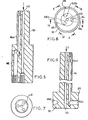
- Fig. 3 is an end view of one form of male member of the coupling;
- Figs. 4 to 6 are cross-sections on the lines IV-IV V-V and VI-VI respectively in Fig. 3;
- Fig.,7 is an end view looking in the direction of arrow Z in Fig. 6;
- Fig. 8 is an end view of a further form of male member of the coupling;
- Figs. 9 - 11 are cross-sections on the lines IX-IX, X-X and XI-XI respectively in Fig. 8;
- Fig. 12 is an end view looking in the direction of arrow Y in Fig. 9;
- Fig. 13 is an end view of a female member of the coupling;
- Figs. 14 - 16 are cross-sections on lines XIV-XIV: XV-XV: XVI-XVI respectively in Fig. 13.
- In Fig.l an
industrial robot arm 10 comprises a main section 12 and ahead section 13 which are relatively pivotable about a transverse axis.14. Thehead section 13 carries a fluid operable device such as atool changer 11. Relative pivotal movement (pitch) aboutaxis 14 is performed by means of arotary tube 15 on the main section 12 drivable in known manner, thetube 15 transmitting drive throughgears head section 13 can be rotated (roll) about its longitudinal axis K by means of atube 9 coaxial withtube 15. Drive fromtube 9 is transmitted to the head section throughgears gears axis 14 - The
head section 13 requires a fluid feed to operate thetool changer 11 and the present invention is concerned with providing a fluid coupling which will enable the feed to be effected. Fluid is supplied to the arm through four lines indicated generally at 22, 23, 24 and 25. The lines communicate with the head via a pair of fluid couplings indicated generally at 26 which enable fluid to pass therethrough during pitch and roll movement. - Figure 2 shows parts of the arm, and particularly the
coupling 26, in greater detail. In Fig.2 twotubes 27, 28 have pairs of overlappinglugs spindle 32 passes with working clearance to permit relative pivoting of the tubes. Thespindle 32 defines theaforesaid axis 14 and is mounted on the main section 12 of the arm. Thetube 27 sealingly contains a female coupling member 33 (shown in detail in Figs. 13 to 16) which receives a male coupling member 34 (shown in detail in Figs. 3 to 7; and the tube 28 sealingly contains afemale coupling member 33a. Themale coupling member 34 is sealingly housed within atube 35 which haslugs 36 between which is mounted a block 31 connected to asupport bar 38. The latter extends throughtube 9 to a convenient mounting point on the main arm section 12, or a suitable alternative support. The fluid feed lines (two of which 22,23 are shown in Fig. 2) are connected torespective barbed connectors 41 on themale member 34 to carry fluid torespective inlet ducts ducts male member 34, in an alternative embodiment these can be in part or whole axial peripheral grooves or flats, sealed e.g. by tubes such as 27,28. A section oftube 23 is not coaxial with the associatedoutlet duct 44. As described below with respect to Figs. 3 to 7 and 13 to 16, when themale member 34 is fitted in thefemale member 33 theinlet ducts respective outlet ducts female member 33, either to allow fluid to flow between the inlet ducts and the respective outlet ducts or to allow fluid pressure to be transmitted. The outlet ducts are fitted withbarbed connectors 41 to which flexible pipes are fitted (two only of which 57,58 are shown). The pipes connectfemale member 33 with an identicalfemale member 33a in tube 28 havingducts ducts male member 60 shown in detail in Figs. 8 to 11. Themale member 60 has ahead 62 through which the outlet ducts extend to enable fluid to flow to various areas of thetool changer 11, the latter being mounted in thehead section 13 via anadaptor plate 68. Whilsttool change 11 can be changed manually, usefully the tool changer has an adaptor e.g. adaptor 72 (Fig. 2) which thehead section 13 can approach, pick up and subsequently release; there may be a series of tool changers which therobot arm 10 can selectively engage, and subsequently position and drive.Outlet duct 63 may carry fluid for raising apiston 70 in the tool changer,outlet 65 may carry fluid for loweringpiston 70 andoutlet ducts carrier 11 via an adaptor 72. The tool carrier is described in more detail below. - Referring now to Figs. 3 to 6 the
male member 34 is formed with three axial bores from the larger diameter end arranged as shown in Fig.3. The central bore definesduct 43, while the remaining bores defineducts radial ports diameter section 80. The ports are axially spaced so as to align with respective grooves in the associated female member. In Figs. 13 to 16 thefemale member 33 has its internal periphery formed withgrooves 1 to 7. The lower end of themember 33 as shown is formed with four axial bores. The central bore defines theduct 53 and the remaining bores define together with axial grooves along the outer surface of the female member theducts Duct 54 terminates atinternal groove 6,duct 56 terminates atinternal groove 4 andduct 55 terminates atinternal groove 2. When themale member 34 is positioned within the female member, theports grooves ducts ducts duct 43 can flow directly toduct 53. 0-ring382 are located in the remaininggrooves male member 60 shown in Figs. 8 to 12 is of similar construction to that shown in Figs. 3 to 7 except for thehead 62. At one end, thebores ports ports head 62. When themale member 60 is positioned within thefemale member 33a theports internal grooves ducts ducts duct 53 flows directly toduct 63. - The
female members tubes 27, 28 to prevent leakage between the axial external grooves in the female members. - The male and female coupling members permit relative rotary movement to occur between them without interruption of fluid flow and the four sections of flexible tubing (57, 58) being shown in Fig.2 interconnecting the female members across the
spindle 32 enables the pitch to be varied without interruption of fluid flow. If desired the male members could have grooved surfaces which co-operate with non-grooved internal surfaces of the female members. - Looking in more detail at the
tool carrier 11, thepiston 70 is slidable in acylinder 90 to raise I or lower the tapered pin 73. The pin has a reduceddiameter dowel 92 at its lower end which locates accurately in abush 93 in the carrier body. Thecarrier 11 is formed with a frusto-conical location 94 for a complementary shapedprojection 95 on the adapter 72. Theprojection 95 carries aflange 96 formed with atapered bore 97 having substantially the same angle of taper as pin 73. To locate the adapter 72 in thecarrier 11, thepiston 70 is raised to lift the pin 73. Theprojection 95 is then located in thelocation 94 and the piston is urged downwards so that the pin 73 enters bore 97 and engages the left hand surface of the bore as shown in broken lines in Fig.2. That causes theprojection 95 to be urged firmly against thelocation 94 with adjacent surfaces of the carrier and adapter spaced by distance S to prevent abutment. Thedowel 92 finally locates in thebush 93 to lock the adapter in place. An 0-ring seal 98 on the adapter 72 ensures a fluid tight seal between a fluid feed via apassage 66b in the carrier and a passage 66c in the adapter 72. Similar seals can be used to effect sealing between any further surfaces of the carrier and adapter where fluid is to flow therebetween. - A
further dowel 99 locates in abore 100 in the adapter 72 to assist initial alignment of thecarrier 11 and adapter 72. - The adapter can be conveniently picked up by controlled movement of the robot arm 12 and operation of valves (not shown) to control the
piston 70. - The invention also relates to a tool carrier. According to this aspect of the invention there is provided a tool carrier comprising a movable retainer element arranged to retain or release a tool or a member on which . the tool is to be carried, the element having a wedge surface so that movement thereof will urge the tool or member on which the tool is to be carried in a direction transverse to the direction of said movement and into firm engagement with a surface on the tool carrier.
- The retainer element may be an axially movable pin e.g. a tapered pin.
- The retainer element may include a section such as a dowel which engages locating means such as a bush to hold the tool or said member firmly in position.
- The retainer element may be movable by a piston.
- The tool or member may be formed with a duct for fluid which aligns with a duct in said tool carrier and, in such a case, sealing means may be provided between the carrier and a surface of the tool or member to inhibit leakage from the ducts during passage of fluid therethrough.
- The tool carrier is preferably mounted on the arm of an industrial robot.
Claims (14)
1. A fluid tight coupling including an axially-extending female member, an axially-extending male member coaxial with said female member and fitted therewithin, one of said members defining a plurality of inlet ducts, the other of said member defining a plurality of outlet ducts, characterised in that said one of said members defines at least three inlet ducts and in that the other of said members defines at least three outlet ducts.
2. A fluid-tight coupling according to claim 1 characterised in that at least two of said inlet ducts include sections which are not coaxial with the associated two of said outlet ducts.
3. A fluid-tight coupling according to claim 1 or claim 2 characterised in that said at least two of said inlet ducts communicate with the associated said two of said outlet ducts at terminal positions which are spaced apart in the axial direction.
4. A fluid-tight coupling according to claim 3 characterised in that sealing means are positioned between said terminal positions.
5. A fluid-tight coupling according to any of claims 1 - 4 characterised in that at least one of the said inlet ducts and at least one of the said outlet ducts extend substantially coaxially through the respective male and female members.
6. A fluid-tight coupling according to any of claims 1 - 5 characterised in that one of said members has two ducts which terminate at a peripheral portion thereof, and in that the other of said members has two internal peripheral grooves which are aligned respectively with said two ducts.
7. A fluid-tight coupling according to any of claims 1 - 6 characterised in that said members are relatively rotatable about a common axis.
8. A fluid-tight coupling according to any preceding claim characterised in that the outlet ducts are connected to the inlet ducts of a fluid-tight coupling as claimed in any of claims 1 - 7 by flexible conduit means.
9. A fluid-tight coupling as claimed in claim 8 characterised in that the coupling is part of an arm, said arm comprising a first section, a second section pivotally mounted on the first section to enable the two sections to be pivoted relative to each other about a transverse axis, each of said sections having a fluid-tight coupling as claimed in any of claims 1 - 8. 1
10. A fluid-tight coupling as claimed in claim 9 characterised in that one of the said sections carries a device, the device being fluid-connected to the fluid tight couplings in said first and second sections to be operated by fluid which passes through said couplings.
11. A fluid-tight coupling as claimed in claim 10 characterised in that said device includes a device housing, said housing comprising a cylinder, and a piston movable in the cylinder, the piston carrying a tapered locating pin adapted to locate a replaceable tool holder.
12. A fluid-tight coupling as claimed in claim 11 characterised in that one of said ducts has a connection to one end of the cylinder, and in that another of said ducts has a connection to the other end of the cylinder, the piston being axially movable by fluid pressure in said cylinder from a first position to a second position between said connections, a transverse opening in said device, the tool holder being removably located in said opening, the tool holder having a frusto-conical bore, a tapered pin carried by the piston and aligned with said bore, the pin being axially movable into and out of engagement with a bore internal surface upon axial movement of said piston from said first to said second position and from said second to said first position respectively to urge the tool holder against a tool holder locating surface.
13. A tool carrier for use with a fluid-tight, coupling as claimed in any of claims 1 - 12 characterised by a movable retainer element arranged to releasably retain a tool part, the said retainer element having a wedge surface such that movement thereof will urge the tool part in a direction transverse to the direction of said movement and into firm engagement with a surface on the tool carrier.
14. A tool carrier as claimed in claim 13 characterised in that the tool part is a tool holder in which the tool is releasably retained.
Applications Claiming Priority (2)
| Application Number | Priority Date | Filing Date | Title |
|---|---|---|---|
| GB858503046A GB8503046D0 (en) | 1985-02-06 | 1985-02-06 | Fluid tight coupling & tool carrier |
| GB8503046 | 1985-02-06 |
Publications (1)
| Publication Number | Publication Date |
|---|---|
| EP0190907A1 true EP0190907A1 (en) | 1986-08-13 |
Family
ID=10574056
Family Applications (1)
| Application Number | Title | Priority Date | Filing Date |
|---|---|---|---|
| EP86300714A Withdrawn EP0190907A1 (en) | 1985-02-06 | 1986-02-03 | A fluid tight coupling and a tool carrier |
Country Status (3)
| Country | Link |
|---|---|
| EP (1) | EP0190907A1 (en) |
| JP (1) | JPS61248995A (en) |
| GB (1) | GB8503046D0 (en) |
Cited By (1)
| Publication number | Priority date | Publication date | Assignee | Title |
|---|---|---|---|---|
| US8498741B2 (en) | 2009-09-22 | 2013-07-30 | Gm Global Technology Operations | Dexterous humanoid robotic wrist |
Citations (5)
| Publication number | Priority date | Publication date | Assignee | Title |
|---|---|---|---|---|
| US2990851A (en) * | 1958-06-23 | 1961-07-04 | Mcevoy Co | Multiple valve and connection |
| FR2230241A5 (en) * | 1973-05-14 | 1974-12-13 | Sigma Diesel | Rotating joint for lathe turret - has series of annular lubricating oil grooves in rotating sleeve |
| GB2074686A (en) * | 1980-04-24 | 1981-11-04 | Gewerk Eisenhuette Westfalia | Multi line hose or cable connector |
| FR2508360A1 (en) * | 1981-06-25 | 1982-12-31 | Paul Hydraulique | Feed control for expanding reaming tool - has sensor to gauge discharge of air through clearance gap between tool and work to effect control |
| FR2531764A1 (en) * | 1982-08-10 | 1984-02-17 | Jacottet Sa Ets P | Device for the distribution of high pressure hydraulic fluid in a member rotating at high speed. |
-
1985
- 1985-02-06 GB GB858503046A patent/GB8503046D0/en active Pending
-
1986
- 1986-02-03 EP EP86300714A patent/EP0190907A1/en not_active Withdrawn
- 1986-02-06 JP JP2490686A patent/JPS61248995A/en active Pending
Patent Citations (5)
| Publication number | Priority date | Publication date | Assignee | Title |
|---|---|---|---|---|
| US2990851A (en) * | 1958-06-23 | 1961-07-04 | Mcevoy Co | Multiple valve and connection |
| FR2230241A5 (en) * | 1973-05-14 | 1974-12-13 | Sigma Diesel | Rotating joint for lathe turret - has series of annular lubricating oil grooves in rotating sleeve |
| GB2074686A (en) * | 1980-04-24 | 1981-11-04 | Gewerk Eisenhuette Westfalia | Multi line hose or cable connector |
| FR2508360A1 (en) * | 1981-06-25 | 1982-12-31 | Paul Hydraulique | Feed control for expanding reaming tool - has sensor to gauge discharge of air through clearance gap between tool and work to effect control |
| FR2531764A1 (en) * | 1982-08-10 | 1984-02-17 | Jacottet Sa Ets P | Device for the distribution of high pressure hydraulic fluid in a member rotating at high speed. |
Cited By (1)
| Publication number | Priority date | Publication date | Assignee | Title |
|---|---|---|---|---|
| US8498741B2 (en) | 2009-09-22 | 2013-07-30 | Gm Global Technology Operations | Dexterous humanoid robotic wrist |
Also Published As
| Publication number | Publication date |
|---|---|
| JPS61248995A (en) | 1986-11-06 |
| GB8503046D0 (en) | 1985-03-06 |
Similar Documents
| Publication | Publication Date | Title |
|---|---|---|
| US4778315A (en) | Chip removal and tool lubricating device and method | |
| US4459898A (en) | Streamlined multi-axis robot wrist assembly with partially enclosed hydraulic and electrical lines to minimize the wrist envelope | |
| JPS59175984A (en) | Hand exchanger for industrial robot | |
| EP1275469B1 (en) | Tool holder for a machine tool and tool assembly | |
| US4534734A (en) | Swivel dental handpiece | |
| US4538639A (en) | Robot wrist of an industrial robot | |
| JP2002530210A (en) | Milling equipment for pipe cleaning and regeneration technology | |
| US4860638A (en) | Actuator driving system | |
| EP0190907A1 (en) | A fluid tight coupling and a tool carrier | |
| US5901967A (en) | Changeable chuck system | |
| AU731482B2 (en) | Toolholder having impeller-type coolant inducer | |
| US5458379A (en) | Valve-coupling assembly | |
| JP2024023400A (en) | Fluid-operated gripping device and method for holding workpieces in working direction | |
| JPS63187019A (en) | Gas torch with pivotally attached extensible body | |
| EP1123774A2 (en) | Back-up clamp | |
| US3973752A (en) | Quick disconnect coupling for coaxial fluid lines | |
| EP0074991B1 (en) | Hose coupling | |
| JP2694299B2 (en) | Female joint part and joint using the same | |
| US5195227A (en) | Quick change mounting system for machine tools | |
| US4575062A (en) | Coupling construction and clamp therefor | |
| JP3452646B2 (en) | Automatic hand changing equipment | |
| WO1991010810A1 (en) | Improved double wall hydraulic cylinder | |
| JP2002501158A (en) | Multifunctional tube bundle and industrial robot equipped with it | |
| JPH0220367B2 (en) | ||
| JPH1086004A (en) | Fluid supplying device |
Legal Events
| Date | Code | Title | Description |
|---|---|---|---|
| PUAI | Public reference made under article 153(3) epc to a published international application that has entered the european phase |
Free format text: ORIGINAL CODE: 0009012 |
|
| AK | Designated contracting states |
Kind code of ref document: A1 Designated state(s): DE GB IT SE |
|
| STAA | Information on the status of an ep patent application or granted ep patent |
Free format text: STATUS: THE APPLICATION IS DEEMED TO BE WITHDRAWN |
|
| 18D | Application deemed to be withdrawn |
Effective date: 19870414 |
|
| RIN1 | Information on inventor provided before grant (corrected) |
Inventor name: LOVE, ANDREW |