EP0190751A2 - Schwenkbares einachsiges Drehgestell eines Schienenfahrzeuges und Schienenfahrzeug - Google Patents
Schwenkbares einachsiges Drehgestell eines Schienenfahrzeuges und Schienenfahrzeug Download PDFInfo
- Publication number
- EP0190751A2 EP0190751A2 EP86101520A EP86101520A EP0190751A2 EP 0190751 A2 EP0190751 A2 EP 0190751A2 EP 86101520 A EP86101520 A EP 86101520A EP 86101520 A EP86101520 A EP 86101520A EP 0190751 A2 EP0190751 A2 EP 0190751A2
- Authority
- EP
- European Patent Office
- Prior art keywords
- truck
- railcar
- damper
- axle
- yaw
- Prior art date
- Legal status (The legal status is an assumption and is not a legal conclusion. Google has not performed a legal analysis and makes no representation as to the accuracy of the status listed.)
- Granted
Links
Images


Classifications
-
- B—PERFORMING OPERATIONS; TRANSPORTING
- B61—RAILWAYS
- B61F—RAIL VEHICLE SUSPENSIONS, e.g. UNDERFRAMES, BOGIES OR ARRANGEMENTS OF WHEEL AXLES; RAIL VEHICLES FOR USE ON TRACKS OF DIFFERENT WIDTH; PREVENTING DERAILING OF RAIL VEHICLES; WHEEL GUARDS, OBSTRUCTION REMOVERS OR THE LIKE FOR RAIL VEHICLES
- B61F5/00—Constructional details of bogies; Connections between bogies and vehicle underframes; Arrangements or devices for adjusting or allowing self-adjustment of wheel axles or bogies when rounding curves
- B61F5/38—Arrangements or devices for adjusting or allowing self- adjustment of wheel axles or bogies when rounding curves, e.g. sliding axles, swinging axles
-
- B—PERFORMING OPERATIONS; TRANSPORTING
- B61—RAILWAYS
- B61F—RAIL VEHICLE SUSPENSIONS, e.g. UNDERFRAMES, BOGIES OR ARRANGEMENTS OF WHEEL AXLES; RAIL VEHICLES FOR USE ON TRACKS OF DIFFERENT WIDTH; PREVENTING DERAILING OF RAIL VEHICLES; WHEEL GUARDS, OBSTRUCTION REMOVERS OR THE LIKE FOR RAIL VEHICLES
- B61F5/00—Constructional details of bogies; Connections between bogies and vehicle underframes; Arrangements or devices for adjusting or allowing self-adjustment of wheel axles or bogies when rounding curves
- B61F5/02—Arrangements permitting limited transverse relative movements between vehicle underframe or bolster and bogie; Connections between underframes and bogies
- B61F5/22—Guiding of the vehicle underframes with respect to the bogies
- B61F5/24—Means for damping or minimising the canting, skewing, pitching, or plunging movements of the underframes
-
- B—PERFORMING OPERATIONS; TRANSPORTING
- B61—RAILWAYS
- B61F—RAIL VEHICLE SUSPENSIONS, e.g. UNDERFRAMES, BOGIES OR ARRANGEMENTS OF WHEEL AXLES; RAIL VEHICLES FOR USE ON TRACKS OF DIFFERENT WIDTH; PREVENTING DERAILING OF RAIL VEHICLES; WHEEL GUARDS, OBSTRUCTION REMOVERS OR THE LIKE FOR RAIL VEHICLES
- B61F5/00—Constructional details of bogies; Connections between bogies and vehicle underframes; Arrangements or devices for adjusting or allowing self-adjustment of wheel axles or bogies when rounding curves
- B61F5/26—Mounting or securing axle-boxes in vehicle or bogie underframes
- B61F5/30—Axle-boxes mounted for movement under spring control in vehicle or bogie underframes
- B61F5/32—Guides, e.g. plates, for axle-boxes
- B61F5/325—The guiding device including swinging arms or the like to ensure the parallelism of the axles
Definitions
- This invention relates to railcars and, more particularly, to single axle railcar trucks and railcars equipped with single axle trucks.
- United States Patent No. 4,356,775 discloses a fixed, single axle railcar truck that tends to be self-steering when negotiating curved track. This self-steering tendency is produced when the effects of centrifugal force cause the outboard ends of the truck axles to spread apart while simultaneously the inboard ends of the axles are drawn together. Consequently, the axles assume respective radial positions with respect to the curve until the centrifical loading conditions are removed when-the truck resumes straight line travel.
- a principal object of this invention is to provide an improved single axle railcar truck that is self-steering in response to wheel creep forces, with or without centrifugal force self-steering effects.
- Another object of this invention is to provide a swivelable single axle railcar truck that is self-centering.
- Another object of this invention is to provide a swivelable single axle railcar truck that includes independently movable radius arms sprung from an overhead railcar body instead of the truck side frames.
- Still another object of this invention is to provide a railcar that includes two single axle railcar trucks of the type just described.
- a swivelable single axle railcar truck that comprises two parallel damper ramp supports connected together by a transverse tie assembly.
- Two independently movable radius arms are respectively pivoted from the damper ramp supports, and support a single wheeled axle spaced from and in parallel alignment with the transverse tie assembly.
- Two spring elements respectively act between the radius arms and an overhead railcar body so as to independently spring the radius arms from and provide vertical load bearing support with respect to the railcar body.
- a swivel assembly provides horizontal load bearing support with respect to the railcar body about a rotational truck axis adjacent the axle.
- the swivel assembly is supported from the transverse tie assembly, it could be mounted between the damper ramp supports by other transverse tie means, and may or may not include a spring ring providing a self-centering force. While preferably the swivel assembly overlies the axle with the rotational truck axis intersecting the axle, the swivel assembly could be located at other positions adjacent the axle.
- Two yaw control assemblies respectively act between the damper ramp supports and the railcar body for controlling shifting of the damper ramp supports with respect to the railcar body in response to rotative movement of the truck about the rotational truck axis when negotiating curved track.
- each of the yaw control assemblies includes an elongated member or other means movable conjointly with the truck.
- This member forms two opposed surfaces extending in parallel alignment with the general direction of straight line truck travel.
- the yaw assembly compressively grips this member so as to apply a frictional damping force to at least one of these surfaces as they move away from the general direction of straight line truck travel when the truck negotiates curved track.
- the yaw control assembly includes a yaw damper that -provides either a damping force or both a damping force and a self-centering force in response to such movement of the truck.
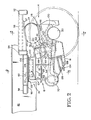
- swivelable single axle railcar truck of this invention is particularly suited for, but not limited to, use in the railcar illustrated in Fig. 1, in which two such trucks (generally referenced by numerals 6 and 8) are used.
- Truck 6 is identical to-truck 8 except that it faces the opposite direction, as shown (Fig. 1). Accordingly, for sake of brevity, only truck 8 is illustrated and described in detail, with parts of truck 6 corresponding to those of truck 8 being designated by the same reference numerals, primed.
- truck 8 comprises two parallel damper ramp supports 10 and 12 that are connected together by a transverse tie assembly 14.
- Two independently movable radius arms 16 and 18 are respectively pivoted from the damper ramp supports for supporting a single wheeled axle 20 spaced from and in parallel alignment with assembly 14.
- Two spring elements 22 and 24 respectively act between the radius arms 16 and 18, and an overhead railcar body (generally referenced by numeral 26) so as to independently spring the radius arms from and provide vertical load bearing support with respect to body 26 at two spaced apart vertical load support points adjacent the ends of axle 20.
- a swivel assembly 28 is supported by two convergent beams 30 and 32 (Fig. 5) from assembly 14 in overlying relation to axle 20.
- the swivel assembly provides horizontal load bearing support with respect to body 26 and provides a vertical rotational axis about which truck 8 can move rotatively when negotiating curved track. In the example illustrated, this rotational truck axis intersects axle 20.
- Two yaw control assemblies 34 and 36 respectively act between the damper ramp supports 10 and 12 and body 26 for controlling horizontal shifting of the damper ramp supports with respect to body 26 in response to rotative movement of truck about the rotational truck axis when negotiating curved track.
- the railcar is particularly suited for, but is not limited to, use as a container-on-flatcar (COFC) or a trailer-on-flatcar (TOFC) designed to .carry. either a single container or a single trailer between 45 and 50 feet in length.
- COFC container-on-flatcar
- TOFC trailer-on-flatcar
- Several such railcars may be formulated into multi-unit trains in which they are articulated together, or may be connected by conventional couplers and employed as single unit railway cars.
- the railcar is or may be suited for either usage, although it is depicted as having a conventional coupler 38 at the end supported by truck 6.
- Body 26 is made up of two parallel, closely spaced apart I-beams 40 and 42 that extend substantially its entire length, and respectively support outboard deck sections 44, 46, 48 and 50 adjacent their ends.
- each of these deck sections is identical. Accordingly, for sake of brevity, only section 50 is shown in detail and described with reference numerals; however, corresponding parts of section 48, to the extent illustrated in Fig. 1, are designated by the same reference numerals, primed.
- Figs. 2-4 the portion of section 50 that overlies the outboard end of axle 20 is reinforced by two box beams 52 and-54 that project perpendicularly from I-beam 42 in an outboard direction. These beams are parallel to, but are spaced apart over, opposite sides of axle 20 so that they generally straddle axle 20 when in its centered position illustrated.
- Another box beam 56 extends between and is supported by beams 52 and 54 generally in overlying alignment with radius arm 18.
- a spring platen 57 is secured to and underlies beam 56, as shown (Fig. 4). This provides reinforcement for the transmission of vertical loads between body 26 and spring element 24, as will be described presently. Spaced from this reinforced portion, the carbody is further reinforced, but to a lesser degree, for operation with assembly 36. This reinforcement is provided by a box beam 58 that projects from I-beam 42, along with two L-beams 60 and 62 that extend between and are supported by beams 58 and 54. Beams 60 and 62 are parallel to and generally spaced apart above the sides of the damper ramp support 12, as shown (Fig. 3).
- Damper ramp support 12 may be of cast or welded construction. In the example, it is of cast construction and is made up of a web reinforced body 64 having a center institutional web 66 and multiple transverse webs 68 of both horizontal and vertical despositions. One end of body 64 forms a web-reinforced journal portion 70 that provides the pivotal support for radius arm 18. The other end of body 64 forms a friction surface 72 (Fig. 2) of suitable composition. This surface cooperates with a damping element carried by radius arm 18 to damp movement of radius arm 18, as will be described presently.
- Body 64 further includes four transversely projecting vertical tabs 74 and two transversely projecting horizontal tabs 76 that extend the length of the body, each of which projects from one of the webs 66, 68. These tabs are symmetrically disposed so that the same body casting can be used either for damper ramp support 10 or damper ramp support 12.
- the transverse tie assembly 14 is made up of two spaced apart, parallel C-beams 78 and 80 that open toward one another. In the example, these beams are secured at their ends to tabs 74 and identical tabs not shown formed by damper ramp support 10. Assembly 14 further includes an elongated strip-like member 82 that extends between beams 78 and 80 and is secured at its ends to tabs 76 and identical tabs not shown formed by damper ramp support 1.0. This member provides torsional stiffness to assembly 14 that resists rotative shifting of the damper ramp support 10 and 12 about a transverse axis through it. The amount of this stiffness should be sufficient to permit the damper ramp support to shift somewhat about this axis in respective vertical planes in order to accommodate the effects of irregularities in track joints, track spacing and other track conditions that may affect the dynamic behavior of the truck.
- the swivel assembly 28 acts between the convergent ends of beams 30 and 32 and I-beams 40 and 42.
- assembly 28 includes a center bowl 84 and a king pin 85.
- Center bowl 84 is mounted by a flange 86 between the inboard flanges of I-beams 40 and 42 by welded lap joints 87.
- Center bowl 84 includes an elastomeric spring ring 88 that is force fit within a cylindrical housing 90 by a shim 92.
- Flange 86 projects transversely from the exterior of housing 90.
- King pin 85 includes a lower annular flange 94 that is secured to center webs 96 of both beams 40 and 42, as shown (Fig. 3). 'King pin 85 projects upwardly from flange 94 and extends coaxially into and through spring ring 88, with which it is engaged by the force produced by shim 92.
- the truck is rotatively moveable about a vertical axis of rotation through the king pin.
- Such movement is resisted, however, by resilient shear forces set up within spring ring 88 in proportion to the extent of the rotational deflection obtained.
- Spring ring 88 thus acts as a source of self-centering force that tends to urge the truck toward a central position corresponding that normally encountered when the truck is traversing straight track.
- This self-centering force is controllable by appropriate selection of the construction of the spring ring. In one presently preferred embodiment of the present invention, however, additional self-centering force is desired, so the truck is equipped with yaw dampers to be described presently.
- each of the yaw control assemblies 34 and 36 includes a yaw damper that provides both frictional damping and self-centering forces.
- a yaw damper that provides both frictional damping and self-centering forces.
- assemblies 34 and 36 are relatively small as compared to the full weight of carbody 26.
- assemblies 34 and 36 allow relative sliding movement between parts mounted by the carbody 26 and truck 8, as will now be described.
- assembly 36 comprises an elongated member 100 forming an upper planar surface and a lower planar surface, both extending in horizontal parallel alignment with the general direction of straight line truck travel.
- Assembly 36 further includes a fixed upper member 98 that is mounted by body 26 in sliding load transmitting relation with the upper surface of member 100, and a yaw damper (generally referred by numeral 104) also mounted by body 26.
- the upper and lower surfaces of member 100 are compressively gripped between member 98 and yaw damper 104 such that a frictional damping force is applied to at least one of these surfaces, preferably the lower one, as they move away from the general direction of straight line truck travel when the truck negotiates curved track.
- Member 98 is mounted by the carbody 26 beneath the reinforced portion bounded by beams 60 and 62, generally in overlying relation with damper ramp support 12.
- Member 98 forms a planar surface 102 having a low coefficient of static friction and a relatively higher coefficient of dynamic friction, preferably twice the coefficient of static friction. This surface slidably bears down upon the upper surface of member 100.
- Member 100 is formed as an elongated strip-like member of generally inverted U-shaped configuration. As most clearly shown in Fig. 2, member 100 is secured at one end to the upper face of damper ramp support 12, and at its other end to the end of damper ramp support 12 adjacent portion 70, so that it extends essentially along the length of damper ramp support 12.
- the upper and lower surfaces at member 100 thus extend in parallel alignment with the length of damper ramp support 12, and hence with the general direction of straight line truck travel when the truck negotiates straight track.
- the lower surface of member 100 slidably bears down upon yaw damper 104.
- . yaw damper 104 is, made up of channel member 106 and a shear/compression spring 108.
- Member 106 is transverse to and underlies member 100, and is secured at its ends by spot welds or the like to the carbody 26, as shown (Fig. 3).
- Member 106 includes a depressed midsection that supports spring 108 so that it is precompressed a predetermined amount against the lower surface of member 100.
- spring 108 includes two bonded end plates 110 and 112 that respectively bear against the lower surface of member 100 and the midsection of member 106, as shown (Fig. 3).
- Member 100 therefore is supported on spring 108 and is effectively gripped between spring 108 and surface 102 in response to the compression force set up in spring 108.
- the frictional damping force obtained is proportional to the resultant of the downward force applied by carbody 26 at surface 102 and the upward normal force exerted by spring 108 against the lower surface of member 100.
- yaw damper 104 This force is controllable in relation to the deflection of spring 108 caused by shifting of member 100 away from the neutral or center position it normally occupies when the truck is in straight line travel. Unlike conventional load responsive yaw dampers, it is possible to control this force so that the frictional damping force obtained remains substantially constant under these conditions. This is accomplished by causing spring 108 to be deflected transversely in shear, as depicted in broken lines in Fig. 3, in response to shifting of member 100 as the truck negotiates a track section having a curvature that tends to cause increased force loading on yaw damper 104. In the example illustrated in Fig.
- spring 108 is depicted in shear on exaggerated scale for clarity, as it would appear when truck 8 negotiates a track section that curves to the left, with truck 8 the lead truck. As it is thus deflected, spring 108 tends to thin down and therefore exerts less compression force upon the lower surface of member 100. During this time, however, the cornering conditions experienced by the truck are such that the downward force appearing at surface 102 has increased. By selecting an appropriate spring construction, this reduction in spring force offsets the increase in downward force so that the frictional damping force obtained remains substantially constant, both during and after the time the truck negotiates the curved track section.. As will be appreciated, similar but oppositely acting effects are obtained when the cornering conditions produce a decrease in downward force at surface 102.
- yaw dampers or centering devices could be used in place of or in addition to swivel assembly 28 and yaw control assemblies 34 and 36; however, to the extent these introduce load sensitivities in the damping forces obtained, performance of the truck may be degraded from that attainable with the presently preferred construction.
- yaw control assemblies 34 and 36 could act as guides only, guiding the truck as it swivels without application of any frictional damping force.
- spring 100 could be eliminated or its effects limited to providing requisite support for member 100.
- the yaw damper illustrated in Figs. 6 and 7 may be used in place of yaw damper 104 to provide load proportional frictional damping.
- This yaw damper is generally similar to yaw damper 104, except that the elastomeric spring is not deflected in shear and hence neither thins down nor exerts a self-centering force.
- Parts of the Figs. 6 and 7 yaw damper corresponding to those of yaw damper 104 are not described further, but are designated by the same reference numerals, primed.
- channel member 106' supports an elastomeric compression spring 208 which, like spring 108, is precompressed and exerts a predetermined normal force against the lower surface of member 100'.
- a plate 210 is interposed between spring 208 and member 100'. Plate. 210 is not secured to spring 208. This plate includes a low friction surface 212 identical to surface 102 that is in face-to- face contact with the lower surface of member 100. Plate 210 therefore is free to shift with respect to member 100 and likewise permits member 100 to shift with respect to spring 208.
- End plates 214 and 216 enclose the ends of member 106' to maintain spring 208 in a fixed position within the channel.
- the swivelable single axle truck of this invention includes two independently damped suspension assemblies that are respectively operable with radium arms 16 and 18. These suspension assemblies are identical and, as in the case of the other identical assemblies described previously, only one, the suspension assembly associated with radius arm 18 (generally referenced in Figs. 2 and 4 by numeral 114) is shown in detail and described with reference numerals.
- spring element 24 is in the form of an elastomeric rod spring that is compressable transversely between upper platen 57 described previously, and a lower platen 116 formed by a force resolving wedge 118.
- This wedge is carried by the end of radius arm 18 in overlying relation to the end of the axle, and is movable within a guide channel formed by the radius arm for movement toward and perpendicular to surface 72 in response to application of a force normal to surface 72.
- a frictional damper 120 is supported by pivot 121 from the thick end of wedge 118, by which it is urged in a normal direction against surface 72.
- Two guide plates 122 are respectively upstanding from the sides of surface 72 to engage and maintain damper 120 in alignment with surface 72 as the end of radius arm 18 pivots vertically.
- wedge 118 resolves a component of the compressive force on spring element 24 into a normal force urging damper 120 into engagement with surface 72.
- the frictional damping force obtained will vary in accordance with this normal force and therefore is proportional to the vertical load applied to spring element 24.
- a brake assembly 124 is mounted by the lower inboard end of radius arm 18. As illustrated in Fig. 2, this assembly includes an open ended mounting channel 126 that opens at one end opposite the wheel flange. A brake member 128 is movable within this channel by an appropriate actuator not shown so as to apply braking effort to the wheel tread. An elastomeric- ally damped adaptor assembly 130 supports axle 20 from the outboard end of radius arm 18. Further details of these and other aspects of the suspension, brake or adaptor assemblies are illustrated and described in the aforesaid U.S. Patent No. 4,356,775.
Landscapes
- Engineering & Computer Science (AREA)
- Mechanical Engineering (AREA)
- Vibration Prevention Devices (AREA)
- Vehicle Body Suspensions (AREA)
- Body Structure For Vehicles (AREA)
- Steering-Linkage Mechanisms And Four-Wheel Steering (AREA)
- Vibration Dampers (AREA)
- Carriers, Traveling Bodies, And Overhead Traveling Cranes (AREA)
- Railway Tracks (AREA)
- Vehicle Cleaning, Maintenance, Repair, Refitting, And Outriggers (AREA)
- Forklifts And Lifting Vehicles (AREA)
- Automobile Manufacture Line, Endless Track Vehicle, Trailer (AREA)
Priority Applications (1)
| Application Number | Priority Date | Filing Date | Title |
|---|---|---|---|
| AT86101520T ATE64125T1 (de) | 1985-02-08 | 1986-02-06 | Schwenkbares einachsiges drehgestell eines schienenfahrzeuges und schienenfahrzeug. |
Applications Claiming Priority (2)
| Application Number | Priority Date | Filing Date | Title |
|---|---|---|---|
| US699739 | 1985-02-08 | ||
| US06/699,739 US4637318A (en) | 1985-02-08 | 1985-02-08 | Swivelable single axle railcar truck and railcar |
Publications (3)
| Publication Number | Publication Date |
|---|---|
| EP0190751A2 true EP0190751A2 (de) | 1986-08-13 |
| EP0190751A3 EP0190751A3 (en) | 1987-06-16 |
| EP0190751B1 EP0190751B1 (de) | 1991-06-05 |
Family
ID=24810690
Family Applications (1)
| Application Number | Title | Priority Date | Filing Date |
|---|---|---|---|
| EP86101520A Expired - Lifetime EP0190751B1 (de) | 1985-02-08 | 1986-02-06 | Schwenkbares einachsiges Drehgestell eines Schienenfahrzeuges und Schienenfahrzeug |
Country Status (11)
| Country | Link |
|---|---|
| US (1) | US4637318A (de) |
| EP (1) | EP0190751B1 (de) |
| JP (1) | JPS61184168A (de) |
| KR (1) | KR890002420B1 (de) |
| CN (1) | CN86101098B (de) |
| AT (1) | ATE64125T1 (de) |
| AU (1) | AU579223B2 (de) |
| CA (1) | CA1231270A (de) |
| DE (1) | DE3679566D1 (de) |
| ES (2) | ES8704824A1 (de) |
| MX (1) | MX162641A (de) |
Cited By (1)
| Publication number | Priority date | Publication date | Assignee | Title |
|---|---|---|---|---|
| AT394980B (de) * | 1988-03-30 | 1992-08-10 | Sgp Verkehrstechnik | Vierachsiges drehgestell fuer schienenfahrzeuge |
Families Citing this family (5)
| Publication number | Priority date | Publication date | Assignee | Title |
|---|---|---|---|---|
| US4802419A (en) * | 1986-10-08 | 1989-02-07 | Urban Transportation Development Corporation | Steered axle for a railway vehicle |
| ES2133229B1 (es) * | 1996-12-24 | 2000-04-16 | Talgo Patentes | Rodadura monoeje con ruedas independientes desplazables para vagones articulados de transporte de automoviles. |
| US7082881B2 (en) * | 2003-01-27 | 2006-08-01 | Ensco, Inc. | Mount apparatus for mounting a measurement device on a rail car |
| DE102018210880A1 (de) * | 2018-07-03 | 2020-01-09 | Siemens Aktiengesellschaft | Radsatzzwischenrahmen für ein Schienenfahrzeug |
| CN111872613B (zh) * | 2020-08-03 | 2022-07-12 | 中车长春轨道客车股份有限公司 | 轨道客车转向架构架组对通用工装 |
Family Cites Families (14)
| Publication number | Priority date | Publication date | Assignee | Title |
|---|---|---|---|---|
| US2680413A (en) * | 1951-03-13 | 1954-06-08 | Becker Anton | Load-stabilizing linkage for metallic cars |
| GB1166652A (en) * | 1966-04-26 | 1969-10-08 | British Railways Board | Improvements relating to Railway Vehicles and Bogies for such Vehicles |
| SE319794B (de) * | 1966-06-15 | 1970-01-26 | S Henriksson | |
| GB1261896A (en) * | 1968-09-17 | 1972-01-26 | British Railways Board | Improvements in or relating to railway vehicles |
| GB1306080A (de) * | 1969-10-13 | 1973-02-07 | ||
| US3961582A (en) * | 1971-10-14 | 1976-06-08 | Hamilton Neil King Paton | Articulated railcar |
| US3910655A (en) * | 1974-04-01 | 1975-10-07 | Midland Ross Corp | Constant contact side bearing |
| CA1071026A (en) * | 1976-02-09 | 1980-02-05 | Herbert Scheffel | Railway vehicle suspension |
| US4134343A (en) * | 1976-09-27 | 1979-01-16 | General Steel Industries, Inc. | Radial axle railway truck |
| US4202276A (en) * | 1977-06-27 | 1980-05-13 | Bi-Modal Corporation | Self-steering wheel-set for convertible railway vehicle |
| US4356775A (en) * | 1978-01-18 | 1982-11-02 | H. Neil Paton | Damped railway car suspension |
| CA1151221A (en) * | 1978-01-18 | 1983-08-02 | E. Frederick Gylland, Jr. | Vehicle suspension |
| CH644555A5 (en) * | 1980-01-30 | 1984-08-15 | Schweizerische Lokomotiv | Device for controlling the swivelling movement of a wheel set of a rail vehicle in a bend |
| DE3047464C2 (de) * | 1980-12-17 | 1982-12-23 | Estel Hoesch Werke Ag, 4600 Dortmund | Lagerung für Drehgestelle von Schienenfahrzeugen |
-
1985
- 1985-02-08 US US06/699,739 patent/US4637318A/en not_active Expired - Fee Related
-
1986
- 1986-01-30 CN CN86101098A patent/CN86101098B/zh not_active Expired
- 1986-02-05 CA CA000501167A patent/CA1231270A/en not_active Expired
- 1986-02-06 AT AT86101520T patent/ATE64125T1/de not_active IP Right Cessation
- 1986-02-06 KR KR1019860000828A patent/KR890002420B1/ko not_active Expired
- 1986-02-06 DE DE8686101520T patent/DE3679566D1/de not_active Expired - Lifetime
- 1986-02-06 JP JP61023061A patent/JPS61184168A/ja active Granted
- 1986-02-06 EP EP86101520A patent/EP0190751B1/de not_active Expired - Lifetime
- 1986-02-07 ES ES551773A patent/ES8704824A1/es not_active Expired
- 1986-02-07 AU AU53301/86A patent/AU579223B2/en not_active Ceased
- 1986-02-07 MX MX1481A patent/MX162641A/es unknown
-
1987
- 1987-01-02 ES ES557280A patent/ES8801155A1/es not_active Expired
Cited By (1)
| Publication number | Priority date | Publication date | Assignee | Title |
|---|---|---|---|---|
| AT394980B (de) * | 1988-03-30 | 1992-08-10 | Sgp Verkehrstechnik | Vierachsiges drehgestell fuer schienenfahrzeuge |
Also Published As
| Publication number | Publication date |
|---|---|
| JPH0457537B2 (de) | 1992-09-11 |
| ES551773A0 (es) | 1987-04-16 |
| EP0190751B1 (de) | 1991-06-05 |
| ES8801155A1 (es) | 1988-01-01 |
| DE3679566D1 (de) | 1991-07-11 |
| JPS61184168A (ja) | 1986-08-16 |
| MX162641A (es) | 1991-06-10 |
| CN86101098B (zh) | 1988-07-20 |
| AU579223B2 (en) | 1988-11-17 |
| KR890002420B1 (ko) | 1989-07-03 |
| AU5330186A (en) | 1986-08-14 |
| ES8704824A1 (es) | 1987-04-16 |
| KR860006375A (ko) | 1986-09-09 |
| ES557280A0 (es) | 1988-01-01 |
| CA1231270A (en) | 1988-01-12 |
| ATE64125T1 (de) | 1991-06-15 |
| EP0190751A3 (en) | 1987-06-16 |
| CN86101098A (zh) | 1986-08-06 |
| US4637318A (en) | 1987-01-20 |
Similar Documents
| Publication | Publication Date | Title |
|---|---|---|
| US4003316A (en) | Articulated railway car trucks | |
| US4480553A (en) | Stabilized railway vehicle | |
| US4455946A (en) | Articulated trucks | |
| US4131069A (en) | Articulated railway car trucks | |
| US4134343A (en) | Radial axle railway truck | |
| US4356775A (en) | Damped railway car suspension | |
| CN102774394B (zh) | 具有自转向装置的铁路货运车厢转向架 | |
| US4244297A (en) | Articulated railway car trucks | |
| US5174218A (en) | Self-steering trucks with side bearings supporting the entire weight of the vehicle | |
| US4151801A (en) | Self-steering railway truck | |
| CA1071026A (en) | Railway vehicle suspension | |
| US4655143A (en) | Articulated trucks | |
| US4237791A (en) | Radial axle railway truck disc brakes | |
| US5235918A (en) | Railway bogie with improved stability and behavior in curves having a slidably mounted axle box arm | |
| US5438934A (en) | Lightweight, improved performance truck | |
| US5647283A (en) | Railway truck and steering apparatus therefor | |
| EP0190752B1 (de) | Gierdämpfer für schwenkbare Drehgestelle von Schienenfahrzeugen | |
| US4352509A (en) | Damped rubber tired vehicle suspension | |
| EP0190751B1 (de) | Schwenkbares einachsiges Drehgestell eines Schienenfahrzeuges und Schienenfahrzeug | |
| US4428301A (en) | Radial axle railway truck | |
| US4781124A (en) | Articulated trucks | |
| US4889054A (en) | Steering arms for self-steering trucks and truck retrofitting method | |
| EP0182339A1 (de) | Dämpfungsvorrichtung in einem Drehgestell für ein Schienenfahrzeug | |
| WO2000013954A1 (en) | 3-piece rail bogie | |
| CA1065190A (en) | Articulated trucks |
Legal Events
| Date | Code | Title | Description |
|---|---|---|---|
| PUAI | Public reference made under article 153(3) epc to a published international application that has entered the european phase |
Free format text: ORIGINAL CODE: 0009012 |
|
| AK | Designated contracting states |
Kind code of ref document: A2 Designated state(s): AT BE CH DE FR GB IT LI LU NL SE |
|
| 17P | Request for examination filed |
Effective date: 19861110 |
|
| PUAL | Search report despatched |
Free format text: ORIGINAL CODE: 0009013 |
|
| AK | Designated contracting states |
Kind code of ref document: A3 Designated state(s): AT BE CH DE FR GB IT LI LU NL SE |
|
| 17Q | First examination report despatched |
Effective date: 19890202 |
|
| GRAA | (expected) grant |
Free format text: ORIGINAL CODE: 0009210 |
|
| AK | Designated contracting states |
Kind code of ref document: B1 Designated state(s): AT BE CH DE FR GB IT LI LU NL SE |
|
| PG25 | Lapsed in a contracting state [announced via postgrant information from national office to epo] |
Ref country code: SE Effective date: 19910605 Ref country code: AT Effective date: 19910605 |
|
| REF | Corresponds to: |
Ref document number: 64125 Country of ref document: AT Date of ref document: 19910615 Kind code of ref document: T |
|
| ITF | It: translation for a ep patent filed | ||
| REF | Corresponds to: |
Ref document number: 3679566 Country of ref document: DE Date of ref document: 19910711 |
|
| ET | Fr: translation filed | ||
| PGFP | Annual fee paid to national office [announced via postgrant information from national office to epo] |
Ref country code: CH Payment date: 19911230 Year of fee payment: 7 |
|
| PG25 | Lapsed in a contracting state [announced via postgrant information from national office to epo] |
Ref country code: LU Free format text: LAPSE BECAUSE OF NON-PAYMENT OF DUE FEES Effective date: 19920229 |
|
| PLBE | No opposition filed within time limit |
Free format text: ORIGINAL CODE: 0009261 |
|
| STAA | Information on the status of an ep patent application or granted ep patent |
Free format text: STATUS: NO OPPOSITION FILED WITHIN TIME LIMIT |
|
| 26N | No opposition filed | ||
| PG25 | Lapsed in a contracting state [announced via postgrant information from national office to epo] |
Ref country code: LI Effective date: 19930228 Ref country code: CH Effective date: 19930228 |
|
| PGFP | Annual fee paid to national office [announced via postgrant information from national office to epo] |
Ref country code: NL Payment date: 19930228 Year of fee payment: 8 |
|
| REG | Reference to a national code |
Ref country code: CH Ref legal event code: PL |
|
| PGFP | Annual fee paid to national office [announced via postgrant information from national office to epo] |
Ref country code: GB Payment date: 19940104 Year of fee payment: 9 |
|
| PGFP | Annual fee paid to national office [announced via postgrant information from national office to epo] |
Ref country code: FR Payment date: 19940121 Year of fee payment: 9 |
|
| PGFP | Annual fee paid to national office [announced via postgrant information from national office to epo] |
Ref country code: DE Payment date: 19940124 Year of fee payment: 9 |
|
| PGFP | Annual fee paid to national office [announced via postgrant information from national office to epo] |
Ref country code: BE Payment date: 19940224 Year of fee payment: 9 |
|
| PG25 | Lapsed in a contracting state [announced via postgrant information from national office to epo] |
Ref country code: NL Effective date: 19940901 |
|
| NLV4 | Nl: lapsed or anulled due to non-payment of the annual fee | ||
| PG25 | Lapsed in a contracting state [announced via postgrant information from national office to epo] |
Ref country code: GB Effective date: 19950206 |
|
| PG25 | Lapsed in a contracting state [announced via postgrant information from national office to epo] |
Ref country code: BE Effective date: 19950228 |
|
| BERE | Be: lapsed |
Owner name: PATON H. NEIL Effective date: 19950228 |
|
| GBPC | Gb: european patent ceased through non-payment of renewal fee |
Effective date: 19950206 |
|
| PG25 | Lapsed in a contracting state [announced via postgrant information from national office to epo] |
Ref country code: FR Effective date: 19951031 |
|
| PG25 | Lapsed in a contracting state [announced via postgrant information from national office to epo] |
Ref country code: DE Effective date: 19951101 |
|
| REG | Reference to a national code |
Ref country code: FR Ref legal event code: ST |
|
| PG25 | Lapsed in a contracting state [announced via postgrant information from national office to epo] |
Ref country code: IT Free format text: LAPSE BECAUSE OF NON-PAYMENT OF DUE FEES;WARNING: LAPSES OF ITALIAN PATENTS WITH EFFECTIVE DATE BEFORE 2007 MAY HAVE OCCURRED AT ANY TIME BEFORE 2007. THE CORRECT EFFECTIVE DATE MAY BE DIFFERENT FROM THE ONE RECORDED. Effective date: 20050206 |