EP0190474B1 - Procedure to measure the level of a liquid by means of elastic waves, and device to carry out such procedure - Google Patents
Procedure to measure the level of a liquid by means of elastic waves, and device to carry out such procedure Download PDFInfo
- Publication number
- EP0190474B1 EP0190474B1 EP85202145A EP85202145A EP0190474B1 EP 0190474 B1 EP0190474 B1 EP 0190474B1 EP 85202145 A EP85202145 A EP 85202145A EP 85202145 A EP85202145 A EP 85202145A EP 0190474 B1 EP0190474 B1 EP 0190474B1
- Authority
- EP
- European Patent Office
- Prior art keywords
- liquid
- tube
- axially moving
- filler tube
- elastic waves
- Prior art date
- Legal status (The legal status is an assumption and is not a legal conclusion. Google has not performed a legal analysis and makes no representation as to the accuracy of the status listed.)
- Expired
Links
- 239000007788 liquid Substances 0.000 title claims abstract description 53
- 238000000034 method Methods 0.000 title claims abstract description 32
- 239000000945 filler Substances 0.000 claims abstract description 45
- 239000011159 matrix material Substances 0.000 claims description 12
- 230000000694 effects Effects 0.000 claims description 6
- 238000012545 processing Methods 0.000 claims description 3
- 230000005540 biological transmission Effects 0.000 abstract description 6
- 238000005259 measurement Methods 0.000 description 29
- 239000000919 ceramic Substances 0.000 description 5
- 230000006978 adaptation Effects 0.000 description 4
- 238000010586 diagram Methods 0.000 description 4
- 230000006870 function Effects 0.000 description 4
- 239000000463 material Substances 0.000 description 4
- 230000008878 coupling Effects 0.000 description 3
- 238000010168 coupling process Methods 0.000 description 3
- 238000005859 coupling reaction Methods 0.000 description 3
- 239000002131 composite material Substances 0.000 description 2
- 230000008030 elimination Effects 0.000 description 2
- 238000003379 elimination reaction Methods 0.000 description 2
- 238000012544 monitoring process Methods 0.000 description 2
- 230000000644 propagated effect Effects 0.000 description 2
- 239000000523 sample Substances 0.000 description 2
- 238000012546 transfer Methods 0.000 description 2
- 238000002604 ultrasonography Methods 0.000 description 2
- 230000003044 adaptive effect Effects 0.000 description 1
- 239000003638 chemical reducing agent Substances 0.000 description 1
- 238000007796 conventional method Methods 0.000 description 1
- 229920001971 elastomer Polymers 0.000 description 1
- 239000000806 elastomer Substances 0.000 description 1
- 238000012423 maintenance Methods 0.000 description 1
- 238000000691 measurement method Methods 0.000 description 1
- 239000008267 milk Substances 0.000 description 1
- 210000004080 milk Anatomy 0.000 description 1
- 235000013336 milk Nutrition 0.000 description 1
- 230000000750 progressive effect Effects 0.000 description 1
- 238000007789 sealing Methods 0.000 description 1
- 230000003068 static effect Effects 0.000 description 1
- 238000004659 sterilization and disinfection Methods 0.000 description 1
- 230000001360 synchronised effect Effects 0.000 description 1
- 238000003466 welding Methods 0.000 description 1
Images


Classifications
-
- G—PHYSICS
- G01—MEASURING; TESTING
- G01F—MEASURING VOLUME, VOLUME FLOW, MASS FLOW OR LIQUID LEVEL; METERING BY VOLUME
- G01F23/00—Indicating or measuring liquid level or level of fluent solid material, e.g. indicating in terms of volume or indicating by means of an alarm
- G01F23/22—Indicating or measuring liquid level or level of fluent solid material, e.g. indicating in terms of volume or indicating by means of an alarm by measuring physical variables, other than linear dimensions, pressure or weight, dependent on the level to be measured, e.g. by difference of heat transfer of steam or water
- G01F23/26—Indicating or measuring liquid level or level of fluent solid material, e.g. indicating in terms of volume or indicating by means of an alarm by measuring physical variables, other than linear dimensions, pressure or weight, dependent on the level to be measured, e.g. by difference of heat transfer of steam or water by measuring variations of capacity or inductance of capacitors or inductors arising from the presence of liquid or fluent solid material in the electric or electromagnetic fields
-
- G—PHYSICS
- G01—MEASURING; TESTING
- G01F—MEASURING VOLUME, VOLUME FLOW, MASS FLOW OR LIQUID LEVEL; METERING BY VOLUME
- G01F23/00—Indicating or measuring liquid level or level of fluent solid material, e.g. indicating in terms of volume or indicating by means of an alarm
- G01F23/22—Indicating or measuring liquid level or level of fluent solid material, e.g. indicating in terms of volume or indicating by means of an alarm by measuring physical variables, other than linear dimensions, pressure or weight, dependent on the level to be measured, e.g. by difference of heat transfer of steam or water
- G01F23/28—Indicating or measuring liquid level or level of fluent solid material, e.g. indicating in terms of volume or indicating by means of an alarm by measuring physical variables, other than linear dimensions, pressure or weight, dependent on the level to be measured, e.g. by difference of heat transfer of steam or water by measuring the variations of parameters of electromagnetic or acoustic waves applied directly to the liquid or fluent solid material
- G01F23/296—Acoustic waves
-
- Y—GENERAL TAGGING OF NEW TECHNOLOGICAL DEVELOPMENTS; GENERAL TAGGING OF CROSS-SECTIONAL TECHNOLOGIES SPANNING OVER SEVERAL SECTIONS OF THE IPC; TECHNICAL SUBJECTS COVERED BY FORMER USPC CROSS-REFERENCE ART COLLECTIONS [XRACs] AND DIGESTS
- Y10—TECHNICAL SUBJECTS COVERED BY FORMER USPC
- Y10S—TECHNICAL SUBJECTS COVERED BY FORMER USPC CROSS-REFERENCE ART COLLECTIONS [XRACs] AND DIGESTS
- Y10S367/00—Communications, electrical: acoustic wave systems and devices
- Y10S367/908—Material level detection, e.g. liquid level
Definitions
- the method of the invention concerns a method of measuring the level of a liquid.
- the method of the invention has the purpose of measuring the level of a liquid by means of elastic waves, which are preferably of an ultrasonic frequency, within a tube running in a lengthwise direction, individual containers full of liquid being obtained from such tube.
- the invention also concerns an apparatus that employs such method.
- the invention shall not be deemed to be limited to such applications and can be employed to measure the level of any liquid within containers of widely varying types.
- Liquid presence sensors are known from EP-A-0 128 708 which comprise a body having a bore extending therethrough, ultrasonic means mounted on the body and arranged to sense the presence of liquid in the bore.
- the sensors are mounted on mounting means in line with the conduit for containing the liquid and the conduit must be interrupted and must be fixed. It is not possible to mount said liquid presence sensors in an axially moving tube.
- a typical application of this invention could concern the field of filling milk containers or other containers made of flexible composite materials.
- such containers are formed at the same time as they are filled, that is to say, a tube of composite material, hereinafter called a “cardboard tube”, is formed from a band of such material.
- Such a cardboard tube is welded along a generating line by means of known techniques and is filled with a liquid up to a given level, which is kept contant.
- An appropriate device cuts such tube into individual containers below the level of the liquid and seals these containers by known methods.
- the present invention has the precise objective of carrying out measurement of the level of liquid in the cardboard tube formed from the band of material, which runs in a lengthwise direction, as we said earlier.
- Such measurement is important in that the level of liquid must not exceed a set maximum level if the liquid is not to run out of the cardboard tube.
- the invention is especially suitable for the measurement of the level of liquids in sterile conditions.
- a purpose of the invention is therefore the provision of a level measurement device which does not require elements working by means of contact, such as floats or similar position transducers.
- the invention has the further purpose of employing directly the filler tube, which is normally included in filling plants, as an element in the chain of transmission of the measurement signal.
- such method of measurement arranges for a signal transmitter and a signal receiver to be positioned respectively on opposite sides of the cardboard tube.
- Such transmitter and receiver cannot be in contact with the cardboard tube because the latter is in continuous lengthwise movement.
- the invention purposes to obtain a method of propagation of the acoustic wave, and more especially of ultrasonic vibrations, with an attenuation having a value such as to enable the signal to be measured and therefore remaining within an acceptable signal/disturbance relationship. This is attained in a preferred embodiment by employing the filler tube itself as an element in the transmission chain.
- an elastic vibration can be transmitted directly to the filler tube by an appropriate transducer.
- the acoustic impedance of transmission from such transducer to the filler tube is adapted advantageously in an excellent manner by means of adapters placed between the transducer and the filler tube.
- the invention provides for the transmission of the signal through the filler tube to take place by means of a mode of radial and flexural vibration of the filler tube itself. This leads to excellent transfer of the signal to the filling liquid.
- the elastic field is propagated only lengthwise in liquids, and therefore a very small fraction of energy would be yielded by the lengthwise mode of the tube to the liquid unless the material of the filler tube had a characteristic impedance very close to that of the liquid.
- the material of the filler tube had a characteristic impedance very close to that of the liquid.
- a mode of vibration has therefore been adopted which can be propagated in the existing filler tube and can transfer energy to the liquid efficiently.
- the invention arranges also for elimination of effects due to the occurrence of stationary waves affecting the filler tube, such elimination being obtained by a modulation of frequency, which will be confined, however, within a few percent of the carrier and which has the purpose of displacing spatially over the surface of the filler tube the maxima and minima of the stationary wave over a period of time. In this way the same average effects as those of a progressive wave are obtained.
- the elastic field emitted by the cardboard tube is extremely directive. This fact is important since it enables the measurements to be performed with a good spatial resolution.
- the invention arranges to receive the signal, output by the cardboard tube as an ultrasonic vibration, in various methods.
- a first preferred embodiment provides for the employment of a matrix of receivers located near the cardboard tube; such matrix consists of a plurality of elements arranged parallel to a generating line of the cardboard tube.
- the resolution which can be obtained in this way is a function of the distance between one and another of such elementary receivers.
- Processing of the signal detected by the elements of the matrices can take place in parallel for all the elements of the matrix or by scanning. It is possible otherwise to arrange for a combined method of measurement.
- This embodiment with several matrices can be used also for the measurement of liquids the free surface of which can readily take up configurations which are inclined or not flat, such as liquids having a high viscosity. In fact, it is possible to process the information thus obtained so as to determine the level, for instance, at the axis of the cardboard tube.
- a second preferred embodiment of the invention provides for the employment of a rotary detector, which will include an angular window to measure the signal. Within such angular window there will be an angle below which the portion of surface of the cardboard tube not occupied by the liquid can be seen and within which the signal detected is virtually nil.
- FIG. 1 the apparatus of the invention bears the reference 10.
- a filler tube 12 is enclosed in an axially movable cardboard tube 11, which is shown here diagrammatically as being an open cylinder.
- cardboard tube 11 is formed from a continuous band and is sealed crosswise below the filler tube 12 so as to form in succession a series of finished containers, which are not shown here.
- Such method of closure is performed, for instance, by heat sealing or ultrasonic welding or other known methods and we shall not dwell on such method.
- a transmitter transducer 15 is positioned in contact with an upper portion of the filler tube 12. Such transmitter transducer 15 thus coupled to the filler tube 12 causes an ultrasonic vibration to be transmitted through the filler tube 12 to a liquid 13 and thus to a wall of the cardboard tube 11.
- a receiver transducer 16 is positioned outside the cardboard tube 11 and can receive an ultrasonic signal emitted by the wall of the cardboard tube 11 itself.
- the transmitter transducer 15 and receiver transducer 16 are shown in a diagrammatic manner in Fig. 1; they will preferably not be coplanar and, for instance, they may be positioned on planes radial to the cardboard tube 11 at 90° to each other, the purpose being to increase the decoupling between the two transducers 15-16.
- the transducers are shown in Fig. 1 as being coplanar.
- Fig. 2 gives a possible embodiment of a transmitter transducer 15 of a type employing piezoelectric ceramic bodies 18.
- An impedance adapter 21 is included in front of the transmitter transducer 15 and in this example is conformed with an exponential form; it serves to adapt acoustic impedance between the transmitter transducer 15 and the filler tube 12.
- An adjustment screw 36 to regulate the pre-loading on a ceramic bodies 18 can also be seen. As we said earlier, the transmitter transducer 15 causes the filler tube 12 to vibrate.
- Fig. 3 shows the vibration mode pre-selected for the filler tube 12. It is possible to see that with this method a crosswise section of the fillter tube 12 is formed with lobes 22 alternatively located in two mutually perpendicular directions. A configuration comprising more than two lobes 22 is obviously possible. In Fig. 3 the deformation of the filler tube 12 has, of course, been exaggerated for illustrative purposes.
- Fig. 4 gives a possible embodiment of the receiver transducer 16, which in this case consists of a matrix 23 of elementary receivers or sensors 17, which are positioned in line along a generating line of the cardboard tube 11.
- the signal received bythese receivers 17 is sentto a measurement unit 24, in which the signal is processed suitably and converted into a level indication.
- the resolution which can be obtained with this system is in proportion to the distance between two elementary transducers 17 of the matrix 23.
- a variant shown in Fig. 11 provides for an electromagnetic-elastic transponder for the remote energisation of a transducer that generates ultrasounds.
- This embodiment enables a transducer of smaller dimensions, preferably in an airtight container, to be employed.
- matrices 23 may be arranged symmetrically around the carboard tube 11.
- such matrices 23 are three in number and will be staggered vertically by a distance of one third of the distance between successive receiver elements 17 of the matrix 23.
- the resolution of the system is increased in this way; or else it is possible to obtain good resolution also with receivers that by themselves provide low resolution; the resolution of the system using several matrices is the same as that of one single matrix with a lesser distance between receiver elements 17.
- Fig. 5 shows a further embodiment of the invention, in which the measurement of a signal 19 is carried out by scanning along a generating line of the cardboard tube 11; such scanning is performed by means of a suitably powered rotary mirror 25.
- a parabolic reflector 26 reflects the signal towards the rotary mirror 25 located at the focus of the parabola. In this way the signal arriving from various points on a generating line of the cardboard tube 11 reaches the receiver transducer 16 located along the same axis as that of the rotary mirror 26.
- Such receiver 16 can be structured as in Fig. 6, for instance.
- a sheath 27 can be seen which is positioned at the rear of a connector 28 in electrical contact with a piezoelectric ceramic body 29, which is the element that monitors the signal.
- the receiver transducer 16 is equipped with a reflector 30, which may have the shape of a cone or parabola and has the task of receiving a greater quantity of energy of the signal; however, such reflector 30 may also not be included.
- Fig. 7 shows the method of measurement carried out by the apparatus of Fig. 5.
- the reference number 31 indicates the scanning of the measurement zone, that is to say, a length along the generating line of the cardboard tube 11 is pre-set within which the measurement is performed. Such length corresponds to a given arc of angular rotation of the rotary mirror 25; within this angular window the measurement is carried out, whereas outside such angular window the receiver transducer 16 remains inactive, as we shall see hereinafter.
- Fig. 7 the level measurement is referenced with 32; the step shown corresponds to the angular portion of rotation of the mirror 25 within which a signal of sufficient amplitude is not detected.
- the rotation of the mirror is such as to ensure a scanning length reaching from the air to the liquid within the scanning window.
- the threshold "s" may be pre-set or be capable of being pre-set or may be adaptive.
- FIG. 8 gives a possible control circuit for the embodiment of Fig. 5.
- a scanner 38 is shown which includes the apparatus of Fig. 5, namely the rotary mirror 25 with its actuation motor and control means.
- a block 37 to set the angular window makes possible the pre-setting of the scanning angle of the rotary mirror 25 and therefore the scanning length along the generating line of the cardboard tube 11.
- Two in-phase coupling blocks 39 and 40 serve to synchronise the monitoring of the signal and the generation of the signal (41) with the rotation of the mirror 25 of Fig. 5.
- the block 41 is a generator or oscillator which sends to the transmitter transducer 15 an electrical signal to be converted into an ultrasonic vibration.
- the receiver transducer 16 sends the signal to a preamplifier 42, whence, the signal reaches a detector 43, which has the task of mesuring the signal reaching the receiver transducer 16 and of providing a means of such signal.
- the detector 43 can work as follows: such detector 43 is synchronised with the rotation of the mirror 25, so that the measurement always takes place during the momentary period corresponding with the scanning of the pre-set angular window. Such period is divided into intervals of a pre-set length. Within each of these intervals the detector 43 measures the maximum of the mean found over a pre-set number of cycles of the carrier. This method eliminates from the measurement any disturbances of a high amplitude, but short duration, without undergoing the effect of flattening of the signal which would arise from the execution of a simple arithmetical mean.
- the signal 33 of Fig. 7 thus obtained is sent to a noise reduction block 44 and thence to a signal processor block 45.
- the signal is compared with the threshold "s" of Fig. 7.
- the time intervening between the beginning of the window and the surpassing of the threshold provides an angular measurement of the level.
- Blocks 46 and 47 in Fig. 8 are two counters which respectively measure the time corresponding to the scanning of the angular window (block 46) and the time corresponding to the scanning of the angular segment running from the beginning of the window to the measurement of the level of the liquid (block 47).
- Such times of the window and level respectively are processed by the signal processor block 48/20 and are converted into a measurement of level, such as, for instance, a linear height corresponding to the actual height of the free surface of the liquid in the cardboard tube 11.
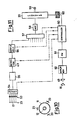
- Fig. 11 gives a block diagram of a possible control system for embodiments such as those shown in Fig. 4 or Fig. 10.
- a controller unit 50 directs the various functions, synchronisation being ensured on the basis of signals arriving from a synchroniser block 60.
- a block 51 performs modulation of frequency of the signal so as to obtain the effect of Fig. 9, as described earlier.
- Piloting of the transmitter transducer 15 is carried out by means of a power amplifier 52 and, in this example, by means of a transponder 49 which permits remote energisation of the transducer 15.
- each of the receiver elements 17 of the matrix 23 is linked to a preamplifier 53.
- the matrix 23 is operated by a low-noise scanner 54.
- the signal reaches a selective amplifier 55 and thence goes to a detector 43 analogous to that of Fig. 8 and having the same function.
- detector 43 produces a means of the signal in this case too, as shown in Fig. 7 for example.
- Block 56 is a sample holder or memory which serves to store the signal coming from one or another of the receiver sensors 17 for a suitable time.
- a possible line scanning block 57 will be employed where several matrices 23 are being used, as in Fig. 10 for instance.
- the signal is converted by an analogue/ digital converter 58 and sent back to a computer 20.
- An output or input unit 59 may be, for instance, a display or another element to show the signal, or may be a control which enables the operator to operate the device.
- the block 60 is a master clock which synchronises all the functions detailed.
Landscapes
- Physics & Mathematics (AREA)
- Electromagnetism (AREA)
- Thermal Sciences (AREA)
- Fluid Mechanics (AREA)
- General Physics & Mathematics (AREA)
- Acoustics & Sound (AREA)
- Engineering & Computer Science (AREA)
- Power Engineering (AREA)
- Measurement Of Levels Of Liquids Or Fluent Solid Materials (AREA)
- Level Indicators Using A Float (AREA)
- Investigating Or Analyzing Materials By The Use Of Ultrasonic Waves (AREA)
- Pens And Brushes (AREA)
- Infusion, Injection, And Reservoir Apparatuses (AREA)
- Treatment Of Fiber Materials (AREA)
Abstract
Description
- This invention concerns a method of measuring the level of a liquid. To be more exact, the method of the invention has the purpose of measuring the level of a liquid by means of elastic waves, which are preferably of an ultrasonic frequency, within a tube running in a lengthwise direction, individual containers full of liquid being obtained from such tube.
- The invention also concerns an apparatus that employs such method. However, the invention shall not be deemed to be limited to such applications and can be employed to measure the level of any liquid within containers of widely varying types.
- Liquid presence sensors are known from EP-A-0 128 708 which comprise a body having a bore extending therethrough, ultrasonic means mounted on the body and arranged to sense the presence of liquid in the bore. The sensors are mounted on mounting means in line with the conduit for containing the liquid and the conduit must be interrupted and must be fixed. It is not possible to mount said liquid presence sensors in an axially moving tube.
- For instance, a typical application of this invention could concern the field of filling milk containers or other containers made of flexible composite materials.
- In a particular method which the invention specifically concerns, such containers are formed at the same time as they are filled, that is to say, a tube of composite material, hereinafter called a "cardboard tube", is formed from a band of such material.
- Such a cardboard tube is welded along a generating line by means of known techniques and is filled with a liquid up to a given level, which is kept contant.
- An appropriate device cuts such tube into individual containers below the level of the liquid and seals these containers by known methods.
- The present invention has the precise objective of carrying out measurement of the level of liquid in the cardboard tube formed from the band of material, which runs in a lengthwise direction, as we said earlier.
- Such measurement is important in that the level of liquid must not exceed a set maximum level if the liquid is not to run out of the cardboard tube. The invention is especially suitable for the measurement of the level of liquids in sterile conditions.
- The known art has employed for such applications hitherto dynamic intrusive elements (for instance, floats) or static elements (conductive probes, for example) within the sterile area, with the relative consequent problems of maintenance and sterilisation operations.
- A purpose of the invention is therefore the provision of a level measurement device which does not require elements working by means of contact, such as floats or similar position transducers. The invention has the further purpose of employing directly the filler tube, which is normally included in filling plants, as an element in the chain of transmission of the measurement signal.
- It has been found that measurement by transmission is not possible by conventional methods since the attenuation of the signal through the cardboard tube is too great.
- In fact, such method of measurement arranges for a signal transmitter and a signal receiver to be positioned respectively on opposite sides of the cardboard tube. Such transmitter and receiver cannot be in contact with the cardboard tube because the latter is in continuous lengthwise movement.
- There is therefore no adaptation of the acoustic impedance in the passage between the source of vibrations (such as ultrasounds), the air, the cardboard tube, the liquid and, once more, the cardboard tube and the air.
- This lack of adaptation of impedance causes a signal attenuation of the order of 120 decibels. When operating in this manner, therefore, it is not possible to carry out any measurement.
- The invention purposes to obtain a method of propagation of the acoustic wave, and more especially of ultrasonic vibrations, with an attenuation having a value such as to enable the signal to be measured and therefore remaining within an acceptable signal/disturbance relationship. This is attained in a preferred embodiment by employing the filler tube itself as an element in the transmission chain.
- It is possible in this way to obtain an adaptation of the acoustic impedance such as to enable a signal of a level sufficient for performance of the measurement to be transmitted. In fact, an elastic vibration can be transmitted directly to the filler tube by an appropriate transducer.
- According to the invention the acoustic impedance of transmission from such transducer to the filler tube is adapted advantageously in an excellent manner by means of adapters placed between the transducer and the filler tube.
- The invention provides for the transmission of the signal through the filler tube to take place by means of a mode of radial and flexural vibration of the filler tube itself. This leads to excellent transfer of the signal to the filling liquid.
- In fact, the elastic field is propagated only lengthwise in liquids, and therefore a very small fraction of energy would be yielded by the lengthwise mode of the tube to the liquid unless the material of the filler tube had a characteristic impedance very close to that of the liquid. For instance, such a result could be obtained by making use of elastomers, but such materials not only entail great attenuation but are also unsuit- . able to embody the filler tube.
- By deforming the surface of the filler tube radially it is possible to induce lengthwise modes in the liquid. By selecting the mode of vibration of the filler tube and the speed of propagation of the sound wave suitably it is possible to obtain an intrinsic adaptation of impedance.
- According to the invention a mode of vibration has therefore been adopted which can be propagated in the existing filler tube and can transfer energy to the liquid efficiently.
- It is possible to act on the geometric dimensions of the filler tube so that its impedance is almost the same as that of the liquid. If the impedance is adapted in this way, the occurrence of backscattering is reduced and a great part of the energy supplied can reach the outer surface of the cardboard.
- The invention arranges also for elimination of effects due to the occurrence of stationary waves affecting the filler tube, such elimination being obtained by a modulation of frequency, which will be confined, however, within a few percent of the carrier and which has the purpose of displacing spatially over the surface of the filler tube the maxima and minima of the stationary wave over a period of time. In this way the same average effects as those of a progressive wave are obtained.
- The elastic field emitted by the cardboard tube is extremely directive. This fact is important since it enables the measurements to be performed with a good spatial resolution.
- Variation in the intensity of the acoustic field in correspondence with the lack of continuity between air and liquid is therefore very steep, thereby permitting a precise measurement even when using receivers which are only slightly directive.
- The invention arranges to receive the signal, output by the cardboard tube as an ultrasonic vibration, in various methods.
- A first preferred embodiment provides for the employment of a matrix of receivers located near the cardboard tube; such matrix consists of a plurality of elements arranged parallel to a generating line of the cardboard tube. The resolution which can be obtained in this way is a function of the distance between one and another of such elementary receivers.
- Processing of the signal detected by the elements of the matrices can take place in parallel for all the elements of the matrix or by scanning. It is possible otherwise to arrange for a combined method of measurement.
- If it is desired to increase the resolution it is possible to arrange several matrices which are arranged symmetrically around the cardboard tube but are staggered in the vertical direction. For instance, if there are three matrices, there will be a staggering of one third of the distance between the receivers of one single matrix.
- This embodiment with several matrices can be used also for the measurement of liquids the free surface of which can readily take up configurations which are inclined or not flat, such as liquids having a high viscosity. In fact, it is possible to process the information thus obtained so as to determine the level, for instance, at the axis of the cardboard tube.
- A second preferred embodiment of the invention provides for the employment of a rotary detector, which will include an angular window to measure the signal. Within such angular window there will be an angle below which the portion of surface of the cardboard tube not occupied by the liquid can be seen and within which the signal detected is virtually nil.
- As the rotation of the detector proceeds, it will pick up immediately afterwards the signal coming from the portion of the container which contains the liquid.
- According to the invention it is possible to arrive at the level of the liquid from the relationship between the angle at which a nil signal is detected and the total aperture of the monitoring window.
- The invention is therefore obtained with a method according to
claim 1 and an apparatus according toClaim 10. - We shall now describe some preferred embodiments of the invention as non-restrictive examples with the help of the attached figures, in which:-
- Fig. 1 gives a diagram of the invention as applied to a filler tube;
- Fig. 2 shows a possible transducer that generates ultrasonic signals;
- Fig. 3 the mode of vibration of the filler tube;
- Fig. 4 gives a digaram of a first embodiment of the invention;
- Fig. 5 shows a second embodiment of the invention;
- Fig. 6 shows a possible transducer for receipt of the signal;
- Fig. 7 shows the method of receipt of the signal;
- Fig. 8 shows a block diagram of the control system of the embodiment of Fig. 5;
- Fig. 9 shows the effect of frequency modulation on the surface of the filler tube;
- Fig. 10 shows a further embodiment of the invention;
- Fig. 11 shows a block diagram of the control system of the embodiments of Fig. 4 or 10.
- In Fig. 1 the apparatus of the invention bears the
reference 10. Afiller tube 12 is enclosed in an axiallymovable cardboard tube 11, which is shown here diagrammatically as being an open cylinder. In the embodiment shownsuch cardboard tube 11 is formed from a continuous band and is sealed crosswise below thefiller tube 12 so as to form in succession a series of finished containers, which are not shown here. Such method of closure is performed, for instance, by heat sealing or ultrasonic welding or other known methods and we shall not dwell on such method. - According to the invention a
transmitter transducer 15 is positioned in contact with an upper portion of thefiller tube 12.Such transmitter transducer 15 thus coupled to thefiller tube 12 causes an ultrasonic vibration to be transmitted through thefiller tube 12 to a liquid 13 and thus to a wall of thecardboard tube 11. According to the invention areceiver transducer 16 is positioned outside thecardboard tube 11 and can receive an ultrasonic signal emitted by the wall of thecardboard tube 11 itself. - The
transmitter transducer 15 andreceiver transducer 16 are shown in a diagrammatic manner in Fig. 1; they will preferably not be coplanar and, for instance, they may be positioned on planes radial to thecardboard tube 11 at 90° to each other, the purpose being to increase the decoupling between the two transducers 15-16. For the sake of simplicity the transducers are shown in Fig. 1 as being coplanar. - Fig. 2 gives a possible embodiment of a
transmitter transducer 15 of a type employing piezoelectricceramic bodies 18. - An
impedance adapter 21 is included in front of thetransmitter transducer 15 and in this example is conformed with an exponential form; it serves to adapt acoustic impedance between thetransmitter transducer 15 and thefiller tube 12. Anadjustment screw 36 to regulate the pre-loading on aceramic bodies 18 can also be seen. As we said earlier, thetransmitter transducer 15 causes thefiller tube 12 to vibrate. - Fig. 3 shows the vibration mode pre-selected for the
filler tube 12. It is possible to see that with this method a crosswise section of thefillter tube 12 is formed withlobes 22 alternatively located in two mutually perpendicular directions. A configuration comprising more than twolobes 22 is obviously possible. In Fig. 3 the deformation of thefiller tube 12 has, of course, been exaggerated for illustrative purposes. - Fig. 4 gives a possible embodiment of the
receiver transducer 16, which in this case consists of amatrix 23 of elementary receivers orsensors 17, which are positioned in line along a generating line of thecardboard tube 11. The signal receivedbythese receivers 17 is sentto ameasurement unit 24, in which the signal is processed suitably and converted into a level indication. - The resolution which can be obtained with this system is in proportion to the distance between two
elementary transducers 17 of thematrix 23. - A variant shown in Fig. 11 provides for an electromagnetic-elastic transponder for the remote energisation of a transducer that generates ultrasounds. This embodiment enables a transducer of smaller dimensions, preferably in an airtight container, to be employed.
- In a further variant shown in Fig. 10
several matrices 23 may be arranged symmetrically around thecarboard tube 11. - In the example shown
such matrices 23 are three in number and will be staggered vertically by a distance of one third of the distance betweensuccessive receiver elements 17 of thematrix 23. The resolution of the system is increased in this way; or else it is possible to obtain good resolution also with receivers that by themselves provide low resolution; the resolution of the system using several matrices is the same as that of one single matrix with a lesser distance betweenreceiver elements 17. - Moreover, with the embodiment of Fig. 10 it is possible to determine the momentary orientation of the free surface in a case also where such surface is not horizontal.
- Fig. 5 shows a further embodiment of the invention, in which the measurement of a
signal 19 is carried out by scanning along a generating line of thecardboard tube 11; such scanning is performed by means of a suitably poweredrotary mirror 25. - In the embodiment shown a
parabolic reflector 26 reflects the signal towards therotary mirror 25 located at the focus of the parabola. In this way the signal arriving from various points on a generating line of thecardboard tube 11 reaches thereceiver transducer 16 located along the same axis as that of therotary mirror 26.Such receiver 16 can be structured as in Fig. 6, for instance. A sheath 27 can be seen which is positioned at the rear of aconnector 28 in electrical contact with a piezoelectricceramic body 29, which is the element that monitors the signal. In this example thereceiver transducer 16 is equipped with a reflector 30, which may have the shape of a cone or parabola and has the task of receiving a greater quantity of energy of the signal; however, such reflector 30 may also not be included. - Fig. 7 shows the method of measurement carried out by the apparatus of Fig. 5. The
reference number 31 indicates the scanning of the measurement zone, that is to say, a length along the generating line of thecardboard tube 11 is pre-set within which the measurement is performed. Such length corresponds to a given arc of angular rotation of therotary mirror 25; within this angular window the measurement is carried out, whereas outside such angular window thereceiver transducer 16 remains inactive, as we shall see hereinafter. - In Fig. 7 the level measurement is referenced with 32; the step shown corresponds to the angular portion of rotation of the
mirror 25 within which a signal of sufficient amplitude is not detected. - When the scanning performed along the generating line of the
cardboard tube 11 reaches the level of the liquid (namely in correspondence with the line of dashes in Fig. 7), there is an increase in thesignal 33 received, which exceeds a given threshold "s". There is a given angular extent of rotation of the mirror in correspondence with such signal received, and in correspondence with such angular extent the signal exceeds the threshold "s" until the end of the scanning. - In the example shown the rotation of the mirror is such as to ensure a scanning length reaching from the air to the liquid within the scanning window. The threshold "s" may be pre-set or be capable of being pre-set or may be adaptive.
- Fig. 8 gives a possible control circuit for the embodiment of Fig. 5. A
scanner 38 is shown which includes the apparatus of Fig. 5, namely therotary mirror 25 with its actuation motor and control means. - A
block 37 to set the angular window makes possible the pre-setting of the scanning angle of therotary mirror 25 and therefore the scanning length along the generating line of thecardboard tube 11. - Two in-phase coupling blocks 39 and 40 serve to synchronise the monitoring of the signal and the generation of the signal (41) with the rotation of the
mirror 25 of Fig. 5. - The
block 41 is a generator or oscillator which sends to thetransmitter transducer 15 an electrical signal to be converted into an ultrasonic vibration. - The
receiver transducer 16 sends the signal to apreamplifier 42, whence, the signal reaches adetector 43, which has the task of mesuring the signal reaching thereceiver transducer 16 and of providing a means of such signal. - According to a possible measurement method the
detector 43 can work as follows:such detector 43 is synchronised with the rotation of themirror 25, so that the measurement always takes place during the momentary period corresponding with the scanning of the pre-set angular window. Such period is divided into intervals of a pre-set length. Within each of these intervals thedetector 43 measures the maximum of the mean found over a pre-set number of cycles of the carrier. This method eliminates from the measurement any disturbances of a high amplitude, but short duration, without undergoing the effect of flattening of the signal which would arise from the execution of a simple arithmetical mean. Thesignal 33 of Fig. 7 thus obtained is sent to anoise reduction block 44 and thence to asignal processor block 45. Here the signal is compared with the threshold "s" of Fig. 7. The time intervening between the beginning of the window and the surpassing of the threshold (seesignal 32 of Fig. 7) provides an angular measurement of the level. - From this angular measurement it is possible to arrive, by geometric considerations, at a linear measurement along the generating line of the
cardboard tube 11. -
Blocks - Such times of the window and level respectively are processed by the signal processor block 48/20 and are converted into a measurement of level, such as, for instance, a linear height corresponding to the actual height of the free surface of the liquid in the
cardboard tube 11. - Fig. 11 gives a block diagram of a possible control system for embodiments such as those shown in Fig. 4 or Fig. 10.
- In this figure a
controller unit 50 directs the various functions, synchronisation being ensured on the basis of signals arriving from asynchroniser block 60. Ablock 51 performs modulation of frequency of the signal so as to obtain the effect of Fig. 9, as described earlier. - Piloting of the
transmitter transducer 15 is carried out by means of apower amplifier 52 and, in this example, by means of atransponder 49 which permits remote energisation of thetransducer 15. - In such embodiment given as an example each of the
receiver elements 17 of thematrix 23 is linked to apreamplifier 53. Thematrix 23 is operated by a low-noise scanner 54. - The signal reaches a selective amplifier 55 and thence goes to a
detector 43 analogous to that of Fig. 8 and having the same function.Such detector 43 produces a means of the signal in this case too, as shown in Fig. 7 for example. -
Block 56 is a sample holder or memory which serves to store the signal coming from one or another of thereceiver sensors 17 for a suitable time. - A possible
line scanning block 57 will be employed whereseveral matrices 23 are being used, as in Fig. 10 for instance. - Lastly, the signal is converted by an analogue/
digital converter 58 and sent back to acomputer 20. - An output or
input unit 59 may be, for instance, a display or another element to show the signal, or may be a control which enables the operator to operate the device. - The
block 60 is a master clock which synchronises all the functions detailed. -
- 10-apparatus
- 11-cardboard tube or container being formed
- 12-filler tube
- 13-liquid
- 14-level of liquid
- 15-transmitter transducer
- 16―receiver transducer
- 17―elementary receivers
- 18-piezoelectric ceramic bodies
- 19-ultrasonic signal
- 20-processing of signal
- 21-impedance adapter
- 22-lobes
- 23-matrix of receivers
- 24-measurement unit
- 25-rotary mirror
- 26-parabolic reflector
- 27-sheath
- 28-connector
- 29-piezoelectric ceramic body
- 30-reflector
- 31-scanning of measurement zone
- 32-signal of level
- 33-output signal of receiver
- 34-stationary waves
- 35-progressive waves
- 36-adjustment screw
- 37-angular window setting
- 38-scanner
- 39-in-phase coupling block
- 40in-phase coupling block
- 41-oscillator
- 42-preamplifier
- 43-detector
- 44-noise reducer
- 45-signal processor block
- 46-window counter
- 47-level counter
- 48―signal processor
- 49-transponder
- 50-controller unit
- 51-frequency modulator
- 52-power amplifier
- 53-preamplifiers
- 54-scanner
- 55-selective amplifier
- 56-memory
- 57-line scanning block
- 58-analogue/digital converter
- 59―output or input unit
- 60-synchroniser block
Claims (19)
Priority Applications (1)
| Application Number | Priority Date | Filing Date | Title |
|---|---|---|---|
| AT85202145T ATE48313T1 (en) | 1985-01-09 | 1985-12-27 | METHOD OF MEASURING THE LEVEL OF A LIQUID BY MEANS OF ELASTIC WAVES AND DEVICE FOR CARRYING OUT THESE METHOD. |
Applications Claiming Priority (2)
| Application Number | Priority Date | Filing Date | Title |
|---|---|---|---|
| IT83305/85A IT1187521B (en) | 1985-01-09 | 1985-01-09 | PROCEDURE FOR MEASURING THE LEVEL OF A LIQUID BY ELASTIC WAVES AND DEVICE CARRYING OUT THIS PROCEDURE |
| IT8330585 | 1985-01-09 |
Publications (2)
| Publication Number | Publication Date |
|---|---|
| EP0190474A1 EP0190474A1 (en) | 1986-08-13 |
| EP0190474B1 true EP0190474B1 (en) | 1989-11-29 |
Family
ID=11319830
Family Applications (1)
| Application Number | Title | Priority Date | Filing Date |
|---|---|---|---|
| EP85202145A Expired EP0190474B1 (en) | 1985-01-09 | 1985-12-27 | Procedure to measure the level of a liquid by means of elastic waves, and device to carry out such procedure |
Country Status (13)
| Country | Link |
|---|---|
| US (1) | US4675660A (en) |
| EP (1) | EP0190474B1 (en) |
| JP (1) | JPS61175525A (en) |
| KR (1) | KR900004738B1 (en) |
| CN (1) | CN1014092B (en) |
| AT (1) | ATE48313T1 (en) |
| AU (1) | AU584150B2 (en) |
| BR (1) | BR8600033A (en) |
| CA (1) | CA1250655A (en) |
| DE (1) | DE3574495D1 (en) |
| IT (1) | IT1187521B (en) |
| SU (1) | SU1667640A3 (en) |
| ZA (1) | ZA859876B (en) |
Cited By (1)
| Publication number | Priority date | Publication date | Assignee | Title |
|---|---|---|---|---|
| EP0436207A1 (en) * | 1989-12-28 | 1991-07-10 | Kureha Chemical Industry Co., Ltd. | Method of detecting a level of liquid in a moving cylindrical body |
Families Citing this family (25)
| Publication number | Priority date | Publication date | Assignee | Title |
|---|---|---|---|---|
| FR2596515B1 (en) * | 1986-03-28 | 1992-07-03 | Univ Paris Curie | LIQUID LEVEL SENSOR WITH GUIDED ELASTIC WAVES |
| SE466418B (en) * | 1989-02-23 | 1992-02-10 | Bror Allan Eriksson | METHOD OF EXAMINATION FOR EXAMINATION OF A LIQUID FILLING IN A CONTAINER AND THE DEVICE TO DETERMINE THE LEVEL OF A OR MULTIPLE INTERFACE WITH A WATER FILLING IN A CONTAINER |
| US5085077A (en) * | 1991-01-07 | 1992-02-04 | Capscan Sales Incorporate | Ultrasonic liquid measuring device for use in storage tanks containing liquids having a non-uniform vapor density |
| IT1269723B (en) * | 1994-05-09 | 1997-04-15 | Tetra Brik Res Dev Spa | METHOD AND EQUIPMENT TO REGISTER A CONTENT LEVEL |
| US5922030A (en) * | 1995-12-20 | 1999-07-13 | Nartron Corporation | Method and system for controlling a solid product release mechanism |
| IT1307699B1 (en) | 1999-05-14 | 2001-11-14 | Tetra Laval Holdings & Finance | PACKAGING MACHINE FOR THE CONTINUOUS PRODUCTION OF SEALED PACKAGES CONTAINING A VERSABLE FOOD PRODUCT |
| WO2001032549A2 (en) | 1999-11-03 | 2001-05-10 | Dispensing Systems Inc. | Apparatus and method for dispensing a carbonated beverage with minimal/controlled foaming under system pressure |
| US20040232173A1 (en) * | 1999-11-10 | 2004-11-25 | Michael Saveliev | Rapid comestible fluid dispensing apparatus and method |
| US6360556B1 (en) | 1999-11-10 | 2002-03-26 | Shurflo Pump Manufacturing Company, Inc. | Apparatus and method for controlling fluid delivery temperature in a dispensing apparatus |
| US6449970B1 (en) | 1999-11-10 | 2002-09-17 | Shurflo Pump Manufacturing Company, Inc. | Refrigeration apparatus and method for a fluid dispensing device |
| US6354341B1 (en) | 1999-11-10 | 2002-03-12 | Shurflo Pump Manufacturing Co., Inc. | Rapid comestible fluid dispensing apparatus and method |
| US6443335B1 (en) | 1999-11-10 | 2002-09-03 | Shurflo Pump Manufacturing Company, Inc. | Rapid comestible fluid dispensing apparatus and method employing a diffuser |
| US6354342B1 (en) | 1999-11-10 | 2002-03-12 | Shurflo Pump Manufacturing Company, Inc. | Hand-held rapid dispensing apparatus and method |
| US6234223B1 (en) | 2000-01-24 | 2001-05-22 | Dispensing Systems, Inc. | Carbonated beverage and ice dispensing system |
| US6237652B1 (en) | 2000-01-25 | 2001-05-29 | Dispensing Systems, Inc. | Pressurized system and method for dispensing carbonated beverage |
| US6234222B1 (en) | 2000-01-24 | 2001-05-22 | Dispensing Systems, Inc. | Automated container positioning apparatus for a carbonated beverage dispensing system |
| DE10312101A1 (en) * | 2003-03-19 | 2004-09-30 | Robert Bosch Gmbh | Device for measuring a level of a liquid in a container |
| BRPI0712187A2 (en) | 2006-06-05 | 2012-03-06 | Liqui-Box Canada Inc. | process and apparatus for forming a minimum confined space bag |
| US8100006B2 (en) * | 2006-08-21 | 2012-01-24 | Engineering Technologies Canada Ltd. | Liquid level measurement device and installation incorporating the same |
| DE102011088880A1 (en) * | 2011-12-16 | 2013-06-20 | Robert Bosch Gmbh | Tubular bag machine for filling a product |
| KR101299050B1 (en) * | 2011-12-30 | 2013-08-21 | 한국항공우주연구원 | Progressive Wave Tube for Fatigue test |
| US9528870B2 (en) | 2013-02-18 | 2016-12-27 | Steven H. Romweber | Liquid reduction timing device |
| DE102014107393B4 (en) * | 2014-05-26 | 2020-04-23 | Krohne S. A. S. | End element for level measuring device and level measuring device |
| KR101601719B1 (en) | 2014-08-28 | 2016-03-09 | 한국항공우주연구원 | Energy sonic simulation tube of heat torch flame and simulation method by the same |
| US20160243818A1 (en) * | 2015-02-23 | 2016-08-25 | Kraft-Schloetels GmbH | Filter system for a printing machine |
Family Cites Families (14)
| Publication number | Priority date | Publication date | Assignee | Title |
|---|---|---|---|---|
| US2787160A (en) * | 1953-06-29 | 1957-04-02 | Sperry Prod Inc | Ultrasonic liquid depth indicator |
| US2998723A (en) * | 1956-06-15 | 1961-09-05 | Acoustica Associates Inc | Sonic wave conductor |
| US3520186A (en) * | 1968-03-11 | 1970-07-14 | Nat Sonics Corp | Ultrasonic fluid interface sensing |
| US3851333A (en) * | 1969-07-31 | 1974-11-26 | S Fishman | Spray injection for testing an ultrasonic liquid level detector |
| US3911642A (en) * | 1972-09-22 | 1975-10-14 | Tetra Pak Int | Method for the sterile packing of a sterile material |
| FR2370638A1 (en) * | 1976-11-12 | 1978-06-09 | Marchadour Yves | BAGGED DOSING MACHINE FEEDING DEVICE |
| US4182177A (en) * | 1978-05-19 | 1980-01-08 | Kamyr, Incorporated | Sound emission level detection |
| JPS5517138A (en) * | 1978-07-24 | 1980-02-06 | Konishiroku Photo Ind Co Ltd | Remaining quantity detector of toner for electrophotographic copier |
| GB2027539B (en) * | 1978-08-09 | 1983-09-21 | Marconi Co Ltd | Measurement of the density of liquids |
| SE445262B (en) * | 1980-10-29 | 1986-06-09 | Brajnandan Sinha | DEVICE FOR SEALING AND INDICATING THE FLUIDUM LEVEL IN KERL |
| US4437497A (en) * | 1981-09-23 | 1984-03-20 | Enander Frederick A | Ultrasonic control of filling a container |
| DE3216604A1 (en) * | 1982-05-04 | 1983-11-10 | Seitz Enzinger Noll Maschinenbau Ag, 6800 Mannheim | FILLING ELEMENT FOR VESSEL FILLING MACHINES FOR FILLING STILLER OR CARBONIC LIQUIDS |
| SE454167B (en) * | 1982-09-27 | 1988-04-11 | Tetra Pak Ab | SET AND DEVICE FOR MANUFACTURING PACKAGING CONTAINERS |
| GB8315650D0 (en) * | 1983-06-07 | 1983-07-13 | Scheme Eng Ltd | Liquid presence sensors |
-
1985
- 1985-01-09 IT IT83305/85A patent/IT1187521B/en active
- 1985-12-24 AU AU51624/85A patent/AU584150B2/en not_active Ceased
- 1985-12-27 EP EP85202145A patent/EP0190474B1/en not_active Expired
- 1985-12-27 AT AT85202145T patent/ATE48313T1/en not_active IP Right Cessation
- 1985-12-27 DE DE8585202145T patent/DE3574495D1/en not_active Expired - Fee Related
- 1985-12-30 ZA ZA859876A patent/ZA859876B/en unknown
- 1985-12-31 CA CA000498837A patent/CA1250655A/en not_active Expired
- 1985-12-31 KR KR1019850010155A patent/KR900004738B1/en not_active Expired
-
1986
- 1986-01-07 SU SU864008374A patent/SU1667640A3/en active
- 1986-01-07 BR BR8600033A patent/BR8600033A/en not_active IP Right Cessation
- 1986-01-08 CN CN86100127A patent/CN1014092B/en not_active Expired
- 1986-01-09 JP JP61002859A patent/JPS61175525A/en active Pending
- 1986-01-09 US US06/817,495 patent/US4675660A/en not_active Expired - Fee Related
Cited By (1)
| Publication number | Priority date | Publication date | Assignee | Title |
|---|---|---|---|---|
| EP0436207A1 (en) * | 1989-12-28 | 1991-07-10 | Kureha Chemical Industry Co., Ltd. | Method of detecting a level of liquid in a moving cylindrical body |
Also Published As
| Publication number | Publication date |
|---|---|
| DE3574495D1 (en) | 1990-01-04 |
| CA1250655A (en) | 1989-02-28 |
| EP0190474A1 (en) | 1986-08-13 |
| KR900004738B1 (en) | 1990-07-05 |
| IT1187521B (en) | 1987-12-23 |
| CN86100127A (en) | 1986-07-16 |
| AU5162485A (en) | 1986-07-17 |
| KR860006035A (en) | 1986-08-16 |
| ATE48313T1 (en) | 1989-12-15 |
| AU584150B2 (en) | 1989-05-18 |
| BR8600033A (en) | 1986-09-23 |
| US4675660A (en) | 1987-06-23 |
| SU1667640A3 (en) | 1991-07-30 |
| CN1014092B (en) | 1991-09-25 |
| IT8583305A0 (en) | 1985-01-09 |
| JPS61175525A (en) | 1986-08-07 |
| ZA859876B (en) | 1986-09-24 |
Similar Documents
| Publication | Publication Date | Title |
|---|---|---|
| US4675660A (en) | Container liquid level sensing utilizing a filling tube | |
| US4914959A (en) | Ultrasonic flow meter using obliquely directed transducers | |
| US4467659A (en) | Transducer having metal housing and employing mode conversion | |
| US2770795A (en) | Acoustic log | |
| US3921442A (en) | Acoustic couplant for use with an ultrasonic search unit | |
| GB2050605A (en) | Ultrasonic device for measuring the specific gravity of liquids | |
| AU5140496A (en) | Three-dimensional digital ultrasound tracking system | |
| AU7059191A (en) | Improvement to gas/liquid ultrasonic flowmeter | |
| EP0813044A3 (en) | Multi-frequency ultrasonic liquid level gauging system | |
| CA2233852A1 (en) | Ultrasonic device for determining bone characteristics | |
| US3021706A (en) | Ultrasonic materials testing system | |
| US4559825A (en) | Transducer array for detection of subsurface flaws | |
| US4020679A (en) | Sled for ultrasonic NDT system | |
| CA2241875A1 (en) | Process and device for determining the level of a fluid using ultrasonic pulses | |
| US4730492A (en) | Measuring the speed of ultrasound in a moving web of paper | |
| US3912954A (en) | Acoustic antenna | |
| US6094986A (en) | Acoustic navigation aid for autonomous coal miner | |
| US2831175A (en) | Electroacoustic transducer | |
| ES8400862A1 (en) | Apparatus for ultrasonic investigation. | |
| JPH01202609A (en) | Probe for ultrasonic thickness measuring apparatus | |
| JPS6484190A (en) | Method and apparatus for monitoring in-pile condition | |
| SU1113735A1 (en) | Device for determination of articles flaws by acoustic emission signals | |
| JP2861295B2 (en) | Surface wave velocity distribution measuring method and apparatus | |
| SU1437773A1 (en) | Method of ultrasonic inspection | |
| SU605162A1 (en) | Acoustic signal reflection coefficient meter |
Legal Events
| Date | Code | Title | Description |
|---|---|---|---|
| PUAI | Public reference made under article 153(3) epc to a published international application that has entered the european phase |
Free format text: ORIGINAL CODE: 0009012 |
|
| AK | Designated contracting states |
Kind code of ref document: A1 Designated state(s): AT BE CH DE FR GB LI LU NL SE |
|
| 17P | Request for examination filed |
Effective date: 19870109 |
|
| 17Q | First examination report despatched |
Effective date: 19880628 |
|
| GRAA | (expected) grant |
Free format text: ORIGINAL CODE: 0009210 |
|
| AK | Designated contracting states |
Kind code of ref document: B1 Designated state(s): AT BE CH DE FR GB LI LU NL SE |
|
| REF | Corresponds to: |
Ref document number: 48313 Country of ref document: AT Date of ref document: 19891215 Kind code of ref document: T |
|
| ET | Fr: translation filed | ||
| REF | Corresponds to: |
Ref document number: 3574495 Country of ref document: DE Date of ref document: 19900104 |
|
| PLBE | No opposition filed within time limit |
Free format text: ORIGINAL CODE: 0009261 |
|
| PLBE | No opposition filed within time limit |
Free format text: ORIGINAL CODE: 0009261 |
|
| STAA | Information on the status of an ep patent application or granted ep patent |
Free format text: STATUS: NO OPPOSITION FILED WITHIN TIME LIMIT |
|
| 26N | No opposition filed | ||
| 26N | No opposition filed | ||
| PGFP | Annual fee paid to national office [announced via postgrant information from national office to epo] |
Ref country code: SE Payment date: 19911120 Year of fee payment: 7 Ref country code: LU Payment date: 19911120 Year of fee payment: 7 |
|
| PGFP | Annual fee paid to national office [announced via postgrant information from national office to epo] |
Ref country code: CH Payment date: 19911121 Year of fee payment: 7 |
|
| PGFP | Annual fee paid to national office [announced via postgrant information from national office to epo] |
Ref country code: FR Payment date: 19911122 Year of fee payment: 7 |
|
| PGFP | Annual fee paid to national office [announced via postgrant information from national office to epo] |
Ref country code: GB Payment date: 19911213 Year of fee payment: 7 |
|
| PGFP | Annual fee paid to national office [announced via postgrant information from national office to epo] |
Ref country code: BE Payment date: 19911217 Year of fee payment: 7 |
|
| PGFP | Annual fee paid to national office [announced via postgrant information from national office to epo] |
Ref country code: AT Payment date: 19911220 Year of fee payment: 7 |
|
| PGFP | Annual fee paid to national office [announced via postgrant information from national office to epo] |
Ref country code: NL Payment date: 19911231 Year of fee payment: 7 |
|
| PGFP | Annual fee paid to national office [announced via postgrant information from national office to epo] |
Ref country code: DE Payment date: 19920130 Year of fee payment: 7 |
|
| EPTA | Lu: last paid annual fee | ||
| PG25 | Lapsed in a contracting state [announced via postgrant information from national office to epo] |
Ref country code: LU Free format text: LAPSE BECAUSE OF NON-PAYMENT OF DUE FEES Effective date: 19921227 Ref country code: GB Effective date: 19921227 Ref country code: AT Effective date: 19921227 |
|
| PG25 | Lapsed in a contracting state [announced via postgrant information from national office to epo] |
Ref country code: SE Effective date: 19921228 |
|
| PG25 | Lapsed in a contracting state [announced via postgrant information from national office to epo] |
Ref country code: LI Effective date: 19921231 Ref country code: CH Effective date: 19921231 Ref country code: BE Effective date: 19921231 |
|
| BERE | Be: lapsed |
Owner name: TETRA DEV-CO CONSORZIO DI STUDIO E RICERCA INDUST Effective date: 19921231 |
|
| PG25 | Lapsed in a contracting state [announced via postgrant information from national office to epo] |
Ref country code: NL Effective date: 19930701 |
|
| NLV4 | Nl: lapsed or anulled due to non-payment of the annual fee | ||
| GBPC | Gb: european patent ceased through non-payment of renewal fee |
Effective date: 19921227 |
|
| PG25 | Lapsed in a contracting state [announced via postgrant information from national office to epo] |
Ref country code: FR Effective date: 19930831 |
|
| REG | Reference to a national code |
Ref country code: CH Ref legal event code: PL |
|
| PG25 | Lapsed in a contracting state [announced via postgrant information from national office to epo] |
Ref country code: DE Effective date: 19930901 |
|
| REG | Reference to a national code |
Ref country code: FR Ref legal event code: ST |
|
| EUG | Se: european patent has lapsed |
Ref document number: 85202145.0 Effective date: 19930709 |