EP0190355A1 - Apparatus for producing high-purity nitrogen gas - Google Patents
Apparatus for producing high-purity nitrogen gas Download PDFInfo
- Publication number
- EP0190355A1 EP0190355A1 EP85903387A EP85903387A EP0190355A1 EP 0190355 A1 EP0190355 A1 EP 0190355A1 EP 85903387 A EP85903387 A EP 85903387A EP 85903387 A EP85903387 A EP 85903387A EP 0190355 A1 EP0190355 A1 EP 0190355A1
- Authority
- EP
- European Patent Office
- Prior art keywords
- nitrogen
- liquid nitrogen
- distillation column
- air
- compressed air
- Prior art date
- Legal status (The legal status is an assumption and is not a legal conclusion. Google has not performed a legal analysis and makes no representation as to the accuracy of the status listed.)
- Granted
Links
Images


Classifications
-
- F—MECHANICAL ENGINEERING; LIGHTING; HEATING; WEAPONS; BLASTING
- F25—REFRIGERATION OR COOLING; COMBINED HEATING AND REFRIGERATION SYSTEMS; HEAT PUMP SYSTEMS; MANUFACTURE OR STORAGE OF ICE; LIQUEFACTION SOLIDIFICATION OF GASES
- F25J—LIQUEFACTION, SOLIDIFICATION OR SEPARATION OF GASES OR GASEOUS OR LIQUEFIED GASEOUS MIXTURES BY PRESSURE AND COLD TREATMENT OR BY BRINGING THEM INTO THE SUPERCRITICAL STATE
- F25J3/00—Processes or apparatus for separating the constituents of gaseous or liquefied gaseous mixtures involving the use of liquefaction or solidification
- F25J3/02—Processes or apparatus for separating the constituents of gaseous or liquefied gaseous mixtures involving the use of liquefaction or solidification by rectification, i.e. by continuous interchange of heat and material between a vapour stream and a liquid stream
- F25J3/04—Processes or apparatus for separating the constituents of gaseous or liquefied gaseous mixtures involving the use of liquefaction or solidification by rectification, i.e. by continuous interchange of heat and material between a vapour stream and a liquid stream for air
- F25J3/044—Processes or apparatus for separating the constituents of gaseous or liquefied gaseous mixtures involving the use of liquefaction or solidification by rectification, i.e. by continuous interchange of heat and material between a vapour stream and a liquid stream for air using a single pressure main column system only
-
- F—MECHANICAL ENGINEERING; LIGHTING; HEATING; WEAPONS; BLASTING
- F17—STORING OR DISTRIBUTING GASES OR LIQUIDS
- F17C—VESSELS FOR CONTAINING OR STORING COMPRESSED, LIQUEFIED OR SOLIDIFIED GASES; FIXED-CAPACITY GAS-HOLDERS; FILLING VESSELS WITH, OR DISCHARGING FROM VESSELS, COMPRESSED, LIQUEFIED, OR SOLIDIFIED GASES
- F17C9/00—Methods or apparatus for discharging liquefied or solidified gases from vessels not under pressure
- F17C9/02—Methods or apparatus for discharging liquefied or solidified gases from vessels not under pressure with change of state, e.g. vaporisation
- F17C9/04—Recovery of thermal energy
-
- F—MECHANICAL ENGINEERING; LIGHTING; HEATING; WEAPONS; BLASTING
- F25—REFRIGERATION OR COOLING; COMBINED HEATING AND REFRIGERATION SYSTEMS; HEAT PUMP SYSTEMS; MANUFACTURE OR STORAGE OF ICE; LIQUEFACTION SOLIDIFICATION OF GASES
- F25J—LIQUEFACTION, SOLIDIFICATION OR SEPARATION OF GASES OR GASEOUS OR LIQUEFIED GASEOUS MIXTURES BY PRESSURE AND COLD TREATMENT OR BY BRINGING THEM INTO THE SUPERCRITICAL STATE
- F25J3/00—Processes or apparatus for separating the constituents of gaseous or liquefied gaseous mixtures involving the use of liquefaction or solidification
- F25J3/02—Processes or apparatus for separating the constituents of gaseous or liquefied gaseous mixtures involving the use of liquefaction or solidification by rectification, i.e. by continuous interchange of heat and material between a vapour stream and a liquid stream
- F25J3/04—Processes or apparatus for separating the constituents of gaseous or liquefied gaseous mixtures involving the use of liquefaction or solidification by rectification, i.e. by continuous interchange of heat and material between a vapour stream and a liquid stream for air
- F25J3/04151—Purification and (pre-)cooling of the feed air; recuperative heat-exchange with product streams
- F25J3/04187—Cooling of the purified feed air by recuperative heat-exchange; Heat-exchange with product streams
- F25J3/04193—Division of the main heat exchange line in consecutive sections having different functions
- F25J3/042—Division of the main heat exchange line in consecutive sections having different functions having an intermediate feed connection
-
- F—MECHANICAL ENGINEERING; LIGHTING; HEATING; WEAPONS; BLASTING
- F25—REFRIGERATION OR COOLING; COMBINED HEATING AND REFRIGERATION SYSTEMS; HEAT PUMP SYSTEMS; MANUFACTURE OR STORAGE OF ICE; LIQUEFACTION SOLIDIFICATION OF GASES
- F25J—LIQUEFACTION, SOLIDIFICATION OR SEPARATION OF GASES OR GASEOUS OR LIQUEFIED GASEOUS MIXTURES BY PRESSURE AND COLD TREATMENT OR BY BRINGING THEM INTO THE SUPERCRITICAL STATE
- F25J3/00—Processes or apparatus for separating the constituents of gaseous or liquefied gaseous mixtures involving the use of liquefaction or solidification
- F25J3/02—Processes or apparatus for separating the constituents of gaseous or liquefied gaseous mixtures involving the use of liquefaction or solidification by rectification, i.e. by continuous interchange of heat and material between a vapour stream and a liquid stream
- F25J3/04—Processes or apparatus for separating the constituents of gaseous or liquefied gaseous mixtures involving the use of liquefaction or solidification by rectification, i.e. by continuous interchange of heat and material between a vapour stream and a liquid stream for air
- F25J3/04151—Purification and (pre-)cooling of the feed air; recuperative heat-exchange with product streams
- F25J3/04187—Cooling of the purified feed air by recuperative heat-exchange; Heat-exchange with product streams
- F25J3/04218—Parallel arrangement of the main heat exchange line in cores having different functions, e.g. in low pressure and high pressure cores
-
- F—MECHANICAL ENGINEERING; LIGHTING; HEATING; WEAPONS; BLASTING
- F25—REFRIGERATION OR COOLING; COMBINED HEATING AND REFRIGERATION SYSTEMS; HEAT PUMP SYSTEMS; MANUFACTURE OR STORAGE OF ICE; LIQUEFACTION SOLIDIFICATION OF GASES
- F25J—LIQUEFACTION, SOLIDIFICATION OR SEPARATION OF GASES OR GASEOUS OR LIQUEFIED GASEOUS MIXTURES BY PRESSURE AND COLD TREATMENT OR BY BRINGING THEM INTO THE SUPERCRITICAL STATE
- F25J3/00—Processes or apparatus for separating the constituents of gaseous or liquefied gaseous mixtures involving the use of liquefaction or solidification
- F25J3/02—Processes or apparatus for separating the constituents of gaseous or liquefied gaseous mixtures involving the use of liquefaction or solidification by rectification, i.e. by continuous interchange of heat and material between a vapour stream and a liquid stream
- F25J3/04—Processes or apparatus for separating the constituents of gaseous or liquefied gaseous mixtures involving the use of liquefaction or solidification by rectification, i.e. by continuous interchange of heat and material between a vapour stream and a liquid stream for air
- F25J3/04248—Generation of cold for compensating heat leaks or liquid production, e.g. by Joule-Thompson expansion
- F25J3/04254—Generation of cold for compensating heat leaks or liquid production, e.g. by Joule-Thompson expansion using the cold stored in external cryogenic fluids
- F25J3/0426—The cryogenic component does not participate in the fractionation
-
- F—MECHANICAL ENGINEERING; LIGHTING; HEATING; WEAPONS; BLASTING
- F25—REFRIGERATION OR COOLING; COMBINED HEATING AND REFRIGERATION SYSTEMS; HEAT PUMP SYSTEMS; MANUFACTURE OR STORAGE OF ICE; LIQUEFACTION SOLIDIFICATION OF GASES
- F25J—LIQUEFACTION, SOLIDIFICATION OR SEPARATION OF GASES OR GASEOUS OR LIQUEFIED GASEOUS MIXTURES BY PRESSURE AND COLD TREATMENT OR BY BRINGING THEM INTO THE SUPERCRITICAL STATE
- F25J3/00—Processes or apparatus for separating the constituents of gaseous or liquefied gaseous mixtures involving the use of liquefaction or solidification
- F25J3/02—Processes or apparatus for separating the constituents of gaseous or liquefied gaseous mixtures involving the use of liquefaction or solidification by rectification, i.e. by continuous interchange of heat and material between a vapour stream and a liquid stream
- F25J3/04—Processes or apparatus for separating the constituents of gaseous or liquefied gaseous mixtures involving the use of liquefaction or solidification by rectification, i.e. by continuous interchange of heat and material between a vapour stream and a liquid stream for air
- F25J3/04406—Processes or apparatus for separating the constituents of gaseous or liquefied gaseous mixtures involving the use of liquefaction or solidification by rectification, i.e. by continuous interchange of heat and material between a vapour stream and a liquid stream for air using a dual pressure main column system
- F25J3/0443—A main column system not otherwise provided, e.g. a modified double column flowsheet
-
- F—MECHANICAL ENGINEERING; LIGHTING; HEATING; WEAPONS; BLASTING
- F25—REFRIGERATION OR COOLING; COMBINED HEATING AND REFRIGERATION SYSTEMS; HEAT PUMP SYSTEMS; MANUFACTURE OR STORAGE OF ICE; LIQUEFACTION SOLIDIFICATION OF GASES
- F25J—LIQUEFACTION, SOLIDIFICATION OR SEPARATION OF GASES OR GASEOUS OR LIQUEFIED GASEOUS MIXTURES BY PRESSURE AND COLD TREATMENT OR BY BRINGING THEM INTO THE SUPERCRITICAL STATE
- F25J3/00—Processes or apparatus for separating the constituents of gaseous or liquefied gaseous mixtures involving the use of liquefaction or solidification
- F25J3/02—Processes or apparatus for separating the constituents of gaseous or liquefied gaseous mixtures involving the use of liquefaction or solidification by rectification, i.e. by continuous interchange of heat and material between a vapour stream and a liquid stream
- F25J3/04—Processes or apparatus for separating the constituents of gaseous or liquefied gaseous mixtures involving the use of liquefaction or solidification by rectification, i.e. by continuous interchange of heat and material between a vapour stream and a liquid stream for air
- F25J3/04636—Processes or apparatus for separating the constituents of gaseous or liquefied gaseous mixtures involving the use of liquefaction or solidification by rectification, i.e. by continuous interchange of heat and material between a vapour stream and a liquid stream for air using a hybrid air separation unit, e.g. combined process by cryogenic separation and non-cryogenic separation techniques
-
- F—MECHANICAL ENGINEERING; LIGHTING; HEATING; WEAPONS; BLASTING
- F25—REFRIGERATION OR COOLING; COMBINED HEATING AND REFRIGERATION SYSTEMS; HEAT PUMP SYSTEMS; MANUFACTURE OR STORAGE OF ICE; LIQUEFACTION SOLIDIFICATION OF GASES
- F25J—LIQUEFACTION, SOLIDIFICATION OR SEPARATION OF GASES OR GASEOUS OR LIQUEFIED GASEOUS MIXTURES BY PRESSURE AND COLD TREATMENT OR BY BRINGING THEM INTO THE SUPERCRITICAL STATE
- F25J3/00—Processes or apparatus for separating the constituents of gaseous or liquefied gaseous mixtures involving the use of liquefaction or solidification
- F25J3/02—Processes or apparatus for separating the constituents of gaseous or liquefied gaseous mixtures involving the use of liquefaction or solidification by rectification, i.e. by continuous interchange of heat and material between a vapour stream and a liquid stream
- F25J3/04—Processes or apparatus for separating the constituents of gaseous or liquefied gaseous mixtures involving the use of liquefaction or solidification by rectification, i.e. by continuous interchange of heat and material between a vapour stream and a liquid stream for air
- F25J3/04763—Start-up or control of the process; Details of the apparatus used
- F25J3/04769—Operation, control and regulation of the process; Instrumentation within the process
- F25J3/04812—Different modes, i.e. "runs" of operation
- F25J3/04824—Stopping of the process, e.g. defrosting or deriming; Back-up procedures
-
- F—MECHANICAL ENGINEERING; LIGHTING; HEATING; WEAPONS; BLASTING
- F25—REFRIGERATION OR COOLING; COMBINED HEATING AND REFRIGERATION SYSTEMS; HEAT PUMP SYSTEMS; MANUFACTURE OR STORAGE OF ICE; LIQUEFACTION SOLIDIFICATION OF GASES
- F25J—LIQUEFACTION, SOLIDIFICATION OR SEPARATION OF GASES OR GASEOUS OR LIQUEFIED GASEOUS MIXTURES BY PRESSURE AND COLD TREATMENT OR BY BRINGING THEM INTO THE SUPERCRITICAL STATE
- F25J3/00—Processes or apparatus for separating the constituents of gaseous or liquefied gaseous mixtures involving the use of liquefaction or solidification
- F25J3/02—Processes or apparatus for separating the constituents of gaseous or liquefied gaseous mixtures involving the use of liquefaction or solidification by rectification, i.e. by continuous interchange of heat and material between a vapour stream and a liquid stream
- F25J3/04—Processes or apparatus for separating the constituents of gaseous or liquefied gaseous mixtures involving the use of liquefaction or solidification by rectification, i.e. by continuous interchange of heat and material between a vapour stream and a liquid stream for air
- F25J3/04763—Start-up or control of the process; Details of the apparatus used
- F25J3/04769—Operation, control and regulation of the process; Instrumentation within the process
- F25J3/04854—Safety aspects of operation
- F25J3/0486—Safety aspects of operation of vaporisers for oxygen enriched liquids, e.g. purging of liquids
-
- F—MECHANICAL ENGINEERING; LIGHTING; HEATING; WEAPONS; BLASTING
- F17—STORING OR DISTRIBUTING GASES OR LIQUIDS
- F17C—VESSELS FOR CONTAINING OR STORING COMPRESSED, LIQUEFIED OR SOLIDIFIED GASES; FIXED-CAPACITY GAS-HOLDERS; FILLING VESSELS WITH, OR DISCHARGING FROM VESSELS, COMPRESSED, LIQUEFIED, OR SOLIDIFIED GASES
- F17C2205/00—Vessel construction, in particular mounting arrangements, attachments or identifications means
- F17C2205/03—Fluid connections, filters, valves, closure means or other attachments
- F17C2205/0302—Fittings, valves, filters, or components in connection with the gas storage device
- F17C2205/0323—Valves
- F17C2205/0326—Valves electrically actuated
-
- F—MECHANICAL ENGINEERING; LIGHTING; HEATING; WEAPONS; BLASTING
- F17—STORING OR DISTRIBUTING GASES OR LIQUIDS
- F17C—VESSELS FOR CONTAINING OR STORING COMPRESSED, LIQUEFIED OR SOLIDIFIED GASES; FIXED-CAPACITY GAS-HOLDERS; FILLING VESSELS WITH, OR DISCHARGING FROM VESSELS, COMPRESSED, LIQUEFIED, OR SOLIDIFIED GASES
- F17C2205/00—Vessel construction, in particular mounting arrangements, attachments or identifications means
- F17C2205/03—Fluid connections, filters, valves, closure means or other attachments
- F17C2205/0302—Fittings, valves, filters, or components in connection with the gas storage device
- F17C2205/0341—Filters
-
- F—MECHANICAL ENGINEERING; LIGHTING; HEATING; WEAPONS; BLASTING
- F17—STORING OR DISTRIBUTING GASES OR LIQUIDS
- F17C—VESSELS FOR CONTAINING OR STORING COMPRESSED, LIQUEFIED OR SOLIDIFIED GASES; FIXED-CAPACITY GAS-HOLDERS; FILLING VESSELS WITH, OR DISCHARGING FROM VESSELS, COMPRESSED, LIQUEFIED, OR SOLIDIFIED GASES
- F17C2221/00—Handled fluid, in particular type of fluid
- F17C2221/01—Pure fluids
- F17C2221/011—Oxygen
-
- F—MECHANICAL ENGINEERING; LIGHTING; HEATING; WEAPONS; BLASTING
- F17—STORING OR DISTRIBUTING GASES OR LIQUIDS
- F17C—VESSELS FOR CONTAINING OR STORING COMPRESSED, LIQUEFIED OR SOLIDIFIED GASES; FIXED-CAPACITY GAS-HOLDERS; FILLING VESSELS WITH, OR DISCHARGING FROM VESSELS, COMPRESSED, LIQUEFIED, OR SOLIDIFIED GASES
- F17C2221/00—Handled fluid, in particular type of fluid
- F17C2221/01—Pure fluids
- F17C2221/014—Nitrogen
-
- F—MECHANICAL ENGINEERING; LIGHTING; HEATING; WEAPONS; BLASTING
- F17—STORING OR DISTRIBUTING GASES OR LIQUIDS
- F17C—VESSELS FOR CONTAINING OR STORING COMPRESSED, LIQUEFIED OR SOLIDIFIED GASES; FIXED-CAPACITY GAS-HOLDERS; FILLING VESSELS WITH, OR DISCHARGING FROM VESSELS, COMPRESSED, LIQUEFIED, OR SOLIDIFIED GASES
- F17C2221/00—Handled fluid, in particular type of fluid
- F17C2221/05—Ultrapure fluid
-
- F—MECHANICAL ENGINEERING; LIGHTING; HEATING; WEAPONS; BLASTING
- F17—STORING OR DISTRIBUTING GASES OR LIQUIDS
- F17C—VESSELS FOR CONTAINING OR STORING COMPRESSED, LIQUEFIED OR SOLIDIFIED GASES; FIXED-CAPACITY GAS-HOLDERS; FILLING VESSELS WITH, OR DISCHARGING FROM VESSELS, COMPRESSED, LIQUEFIED, OR SOLIDIFIED GASES
- F17C2223/00—Handled fluid before transfer, i.e. state of fluid when stored in the vessel or before transfer from the vessel
- F17C2223/01—Handled fluid before transfer, i.e. state of fluid when stored in the vessel or before transfer from the vessel characterised by the phase
- F17C2223/0146—Two-phase
- F17C2223/0153—Liquefied gas, e.g. LPG, GPL
- F17C2223/0161—Liquefied gas, e.g. LPG, GPL cryogenic, e.g. LNG, GNL, PLNG
-
- F—MECHANICAL ENGINEERING; LIGHTING; HEATING; WEAPONS; BLASTING
- F17—STORING OR DISTRIBUTING GASES OR LIQUIDS
- F17C—VESSELS FOR CONTAINING OR STORING COMPRESSED, LIQUEFIED OR SOLIDIFIED GASES; FIXED-CAPACITY GAS-HOLDERS; FILLING VESSELS WITH, OR DISCHARGING FROM VESSELS, COMPRESSED, LIQUEFIED, OR SOLIDIFIED GASES
- F17C2223/00—Handled fluid before transfer, i.e. state of fluid when stored in the vessel or before transfer from the vessel
- F17C2223/03—Handled fluid before transfer, i.e. state of fluid when stored in the vessel or before transfer from the vessel characterised by the pressure level
- F17C2223/033—Small pressure, e.g. for liquefied gas
-
- F—MECHANICAL ENGINEERING; LIGHTING; HEATING; WEAPONS; BLASTING
- F17—STORING OR DISTRIBUTING GASES OR LIQUIDS
- F17C—VESSELS FOR CONTAINING OR STORING COMPRESSED, LIQUEFIED OR SOLIDIFIED GASES; FIXED-CAPACITY GAS-HOLDERS; FILLING VESSELS WITH, OR DISCHARGING FROM VESSELS, COMPRESSED, LIQUEFIED, OR SOLIDIFIED GASES
- F17C2225/00—Handled fluid after transfer, i.e. state of fluid after transfer from the vessel
- F17C2225/01—Handled fluid after transfer, i.e. state of fluid after transfer from the vessel characterised by the phase
- F17C2225/0107—Single phase
- F17C2225/0123—Single phase gaseous, e.g. CNG, GNC
-
- F—MECHANICAL ENGINEERING; LIGHTING; HEATING; WEAPONS; BLASTING
- F17—STORING OR DISTRIBUTING GASES OR LIQUIDS
- F17C—VESSELS FOR CONTAINING OR STORING COMPRESSED, LIQUEFIED OR SOLIDIFIED GASES; FIXED-CAPACITY GAS-HOLDERS; FILLING VESSELS WITH, OR DISCHARGING FROM VESSELS, COMPRESSED, LIQUEFIED, OR SOLIDIFIED GASES
- F17C2227/00—Transfer of fluids, i.e. method or means for transferring the fluid; Heat exchange with the fluid
- F17C2227/03—Heat exchange with the fluid
- F17C2227/0302—Heat exchange with the fluid by heating
- F17C2227/0309—Heat exchange with the fluid by heating using another fluid
- F17C2227/0311—Air heating
-
- F—MECHANICAL ENGINEERING; LIGHTING; HEATING; WEAPONS; BLASTING
- F17—STORING OR DISTRIBUTING GASES OR LIQUIDS
- F17C—VESSELS FOR CONTAINING OR STORING COMPRESSED, LIQUEFIED OR SOLIDIFIED GASES; FIXED-CAPACITY GAS-HOLDERS; FILLING VESSELS WITH, OR DISCHARGING FROM VESSELS, COMPRESSED, LIQUEFIED, OR SOLIDIFIED GASES
- F17C2227/00—Transfer of fluids, i.e. method or means for transferring the fluid; Heat exchange with the fluid
- F17C2227/03—Heat exchange with the fluid
- F17C2227/0367—Localisation of heat exchange
- F17C2227/0388—Localisation of heat exchange separate
- F17C2227/039—Localisation of heat exchange separate on the pipes
-
- F—MECHANICAL ENGINEERING; LIGHTING; HEATING; WEAPONS; BLASTING
- F17—STORING OR DISTRIBUTING GASES OR LIQUIDS
- F17C—VESSELS FOR CONTAINING OR STORING COMPRESSED, LIQUEFIED OR SOLIDIFIED GASES; FIXED-CAPACITY GAS-HOLDERS; FILLING VESSELS WITH, OR DISCHARGING FROM VESSELS, COMPRESSED, LIQUEFIED, OR SOLIDIFIED GASES
- F17C2227/00—Transfer of fluids, i.e. method or means for transferring the fluid; Heat exchange with the fluid
- F17C2227/04—Methods for emptying or filling
- F17C2227/045—Methods for emptying or filling by vacuum
-
- F—MECHANICAL ENGINEERING; LIGHTING; HEATING; WEAPONS; BLASTING
- F17—STORING OR DISTRIBUTING GASES OR LIQUIDS
- F17C—VESSELS FOR CONTAINING OR STORING COMPRESSED, LIQUEFIED OR SOLIDIFIED GASES; FIXED-CAPACITY GAS-HOLDERS; FILLING VESSELS WITH, OR DISCHARGING FROM VESSELS, COMPRESSED, LIQUEFIED, OR SOLIDIFIED GASES
- F17C2250/00—Accessories; Control means; Indicating, measuring or monitoring of parameters
- F17C2250/04—Indicating or measuring of parameters as input values
- F17C2250/0404—Parameters indicated or measured
- F17C2250/0408—Level of content in the vessel
-
- F—MECHANICAL ENGINEERING; LIGHTING; HEATING; WEAPONS; BLASTING
- F17—STORING OR DISTRIBUTING GASES OR LIQUIDS
- F17C—VESSELS FOR CONTAINING OR STORING COMPRESSED, LIQUEFIED OR SOLIDIFIED GASES; FIXED-CAPACITY GAS-HOLDERS; FILLING VESSELS WITH, OR DISCHARGING FROM VESSELS, COMPRESSED, LIQUEFIED, OR SOLIDIFIED GASES
- F17C2250/00—Accessories; Control means; Indicating, measuring or monitoring of parameters
- F17C2250/04—Indicating or measuring of parameters as input values
- F17C2250/0404—Parameters indicated or measured
- F17C2250/0439—Temperature
-
- F—MECHANICAL ENGINEERING; LIGHTING; HEATING; WEAPONS; BLASTING
- F17—STORING OR DISTRIBUTING GASES OR LIQUIDS
- F17C—VESSELS FOR CONTAINING OR STORING COMPRESSED, LIQUEFIED OR SOLIDIFIED GASES; FIXED-CAPACITY GAS-HOLDERS; FILLING VESSELS WITH, OR DISCHARGING FROM VESSELS, COMPRESSED, LIQUEFIED, OR SOLIDIFIED GASES
- F17C2265/00—Effects achieved by gas storage or gas handling
- F17C2265/01—Purifying the fluid
- F17C2265/015—Purifying the fluid by separating
-
- F—MECHANICAL ENGINEERING; LIGHTING; HEATING; WEAPONS; BLASTING
- F25—REFRIGERATION OR COOLING; COMBINED HEATING AND REFRIGERATION SYSTEMS; HEAT PUMP SYSTEMS; MANUFACTURE OR STORAGE OF ICE; LIQUEFACTION SOLIDIFICATION OF GASES
- F25J—LIQUEFACTION, SOLIDIFICATION OR SEPARATION OF GASES OR GASEOUS OR LIQUEFIED GASEOUS MIXTURES BY PRESSURE AND COLD TREATMENT OR BY BRINGING THEM INTO THE SUPERCRITICAL STATE
- F25J2200/00—Processes or apparatus using separation by rectification
- F25J2200/30—Processes or apparatus using separation by rectification using a side column in a single pressure column system
-
- F—MECHANICAL ENGINEERING; LIGHTING; HEATING; WEAPONS; BLASTING
- F25—REFRIGERATION OR COOLING; COMBINED HEATING AND REFRIGERATION SYSTEMS; HEAT PUMP SYSTEMS; MANUFACTURE OR STORAGE OF ICE; LIQUEFACTION SOLIDIFICATION OF GASES
- F25J—LIQUEFACTION, SOLIDIFICATION OR SEPARATION OF GASES OR GASEOUS OR LIQUEFIED GASEOUS MIXTURES BY PRESSURE AND COLD TREATMENT OR BY BRINGING THEM INTO THE SUPERCRITICAL STATE
- F25J2200/00—Processes or apparatus using separation by rectification
- F25J2200/50—Processes or apparatus using separation by rectification using multiple (re-)boiler-condensers at different heights of the column
-
- F—MECHANICAL ENGINEERING; LIGHTING; HEATING; WEAPONS; BLASTING
- F25—REFRIGERATION OR COOLING; COMBINED HEATING AND REFRIGERATION SYSTEMS; HEAT PUMP SYSTEMS; MANUFACTURE OR STORAGE OF ICE; LIQUEFACTION SOLIDIFICATION OF GASES
- F25J—LIQUEFACTION, SOLIDIFICATION OR SEPARATION OF GASES OR GASEOUS OR LIQUEFIED GASEOUS MIXTURES BY PRESSURE AND COLD TREATMENT OR BY BRINGING THEM INTO THE SUPERCRITICAL STATE
- F25J2200/00—Processes or apparatus using separation by rectification
- F25J2200/74—Refluxing the column with at least a part of the partially condensed overhead gas
-
- F—MECHANICAL ENGINEERING; LIGHTING; HEATING; WEAPONS; BLASTING
- F25—REFRIGERATION OR COOLING; COMBINED HEATING AND REFRIGERATION SYSTEMS; HEAT PUMP SYSTEMS; MANUFACTURE OR STORAGE OF ICE; LIQUEFACTION SOLIDIFICATION OF GASES
- F25J—LIQUEFACTION, SOLIDIFICATION OR SEPARATION OF GASES OR GASEOUS OR LIQUEFIED GASEOUS MIXTURES BY PRESSURE AND COLD TREATMENT OR BY BRINGING THEM INTO THE SUPERCRITICAL STATE
- F25J2205/00—Processes or apparatus using other separation and/or other processing means
- F25J2205/60—Processes or apparatus using other separation and/or other processing means using adsorption on solid adsorbents, e.g. by temperature-swing adsorption [TSA] at the hot or cold end
-
- F—MECHANICAL ENGINEERING; LIGHTING; HEATING; WEAPONS; BLASTING
- F25—REFRIGERATION OR COOLING; COMBINED HEATING AND REFRIGERATION SYSTEMS; HEAT PUMP SYSTEMS; MANUFACTURE OR STORAGE OF ICE; LIQUEFACTION SOLIDIFICATION OF GASES
- F25J—LIQUEFACTION, SOLIDIFICATION OR SEPARATION OF GASES OR GASEOUS OR LIQUEFIED GASEOUS MIXTURES BY PRESSURE AND COLD TREATMENT OR BY BRINGING THEM INTO THE SUPERCRITICAL STATE
- F25J2210/00—Processes characterised by the type or other details of the feed stream
- F25J2210/42—Nitrogen
-
- F—MECHANICAL ENGINEERING; LIGHTING; HEATING; WEAPONS; BLASTING
- F25—REFRIGERATION OR COOLING; COMBINED HEATING AND REFRIGERATION SYSTEMS; HEAT PUMP SYSTEMS; MANUFACTURE OR STORAGE OF ICE; LIQUEFACTION SOLIDIFICATION OF GASES
- F25J—LIQUEFACTION, SOLIDIFICATION OR SEPARATION OF GASES OR GASEOUS OR LIQUEFIED GASEOUS MIXTURES BY PRESSURE AND COLD TREATMENT OR BY BRINGING THEM INTO THE SUPERCRITICAL STATE
- F25J2245/00—Processes or apparatus involving steps for recycling of process streams
- F25J2245/40—Processes or apparatus involving steps for recycling of process streams the recycled stream being air
-
- F—MECHANICAL ENGINEERING; LIGHTING; HEATING; WEAPONS; BLASTING
- F25—REFRIGERATION OR COOLING; COMBINED HEATING AND REFRIGERATION SYSTEMS; HEAT PUMP SYSTEMS; MANUFACTURE OR STORAGE OF ICE; LIQUEFACTION SOLIDIFICATION OF GASES
- F25J—LIQUEFACTION, SOLIDIFICATION OR SEPARATION OF GASES OR GASEOUS OR LIQUEFIED GASEOUS MIXTURES BY PRESSURE AND COLD TREATMENT OR BY BRINGING THEM INTO THE SUPERCRITICAL STATE
- F25J2245/00—Processes or apparatus involving steps for recycling of process streams
- F25J2245/42—Processes or apparatus involving steps for recycling of process streams the recycled stream being nitrogen
-
- F—MECHANICAL ENGINEERING; LIGHTING; HEATING; WEAPONS; BLASTING
- F25—REFRIGERATION OR COOLING; COMBINED HEATING AND REFRIGERATION SYSTEMS; HEAT PUMP SYSTEMS; MANUFACTURE OR STORAGE OF ICE; LIQUEFACTION SOLIDIFICATION OF GASES
- F25J—LIQUEFACTION, SOLIDIFICATION OR SEPARATION OF GASES OR GASEOUS OR LIQUEFIED GASEOUS MIXTURES BY PRESSURE AND COLD TREATMENT OR BY BRINGING THEM INTO THE SUPERCRITICAL STATE
- F25J2250/00—Details related to the use of reboiler-condensers
- F25J2250/20—Boiler-condenser with multiple exchanger cores in parallel or with multiple re-boiling or condensing streams
-
- F—MECHANICAL ENGINEERING; LIGHTING; HEATING; WEAPONS; BLASTING
- F25—REFRIGERATION OR COOLING; COMBINED HEATING AND REFRIGERATION SYSTEMS; HEAT PUMP SYSTEMS; MANUFACTURE OR STORAGE OF ICE; LIQUEFACTION SOLIDIFICATION OF GASES
- F25J—LIQUEFACTION, SOLIDIFICATION OR SEPARATION OF GASES OR GASEOUS OR LIQUEFIED GASEOUS MIXTURES BY PRESSURE AND COLD TREATMENT OR BY BRINGING THEM INTO THE SUPERCRITICAL STATE
- F25J2250/00—Details related to the use of reboiler-condensers
- F25J2250/30—External or auxiliary boiler-condenser in general, e.g. without a specified fluid or one fluid is not a primary air component or an intermediate fluid
- F25J2250/40—One fluid being air
-
- F—MECHANICAL ENGINEERING; LIGHTING; HEATING; WEAPONS; BLASTING
- F25—REFRIGERATION OR COOLING; COMBINED HEATING AND REFRIGERATION SYSTEMS; HEAT PUMP SYSTEMS; MANUFACTURE OR STORAGE OF ICE; LIQUEFACTION SOLIDIFICATION OF GASES
- F25J—LIQUEFACTION, SOLIDIFICATION OR SEPARATION OF GASES OR GASEOUS OR LIQUEFIED GASEOUS MIXTURES BY PRESSURE AND COLD TREATMENT OR BY BRINGING THEM INTO THE SUPERCRITICAL STATE
- F25J2250/00—Details related to the use of reboiler-condensers
- F25J2250/30—External or auxiliary boiler-condenser in general, e.g. without a specified fluid or one fluid is not a primary air component or an intermediate fluid
- F25J2250/50—One fluid being oxygen
-
- F—MECHANICAL ENGINEERING; LIGHTING; HEATING; WEAPONS; BLASTING
- F25—REFRIGERATION OR COOLING; COMBINED HEATING AND REFRIGERATION SYSTEMS; HEAT PUMP SYSTEMS; MANUFACTURE OR STORAGE OF ICE; LIQUEFACTION SOLIDIFICATION OF GASES
- F25J—LIQUEFACTION, SOLIDIFICATION OR SEPARATION OF GASES OR GASEOUS OR LIQUEFIED GASEOUS MIXTURES BY PRESSURE AND COLD TREATMENT OR BY BRINGING THEM INTO THE SUPERCRITICAL STATE
- F25J2290/00—Other details not covered by groups F25J2200/00 - F25J2280/00
- F25J2290/10—Mathematical formulae, modeling, plot or curves; Design methods
-
- F—MECHANICAL ENGINEERING; LIGHTING; HEATING; WEAPONS; BLASTING
- F25—REFRIGERATION OR COOLING; COMBINED HEATING AND REFRIGERATION SYSTEMS; HEAT PUMP SYSTEMS; MANUFACTURE OR STORAGE OF ICE; LIQUEFACTION SOLIDIFICATION OF GASES
- F25J—LIQUEFACTION, SOLIDIFICATION OR SEPARATION OF GASES OR GASEOUS OR LIQUEFIED GASEOUS MIXTURES BY PRESSURE AND COLD TREATMENT OR BY BRINGING THEM INTO THE SUPERCRITICAL STATE
- F25J2290/00—Other details not covered by groups F25J2200/00 - F25J2280/00
- F25J2290/62—Details of storing a fluid in a tank
-
- Y—GENERAL TAGGING OF NEW TECHNOLOGICAL DEVELOPMENTS; GENERAL TAGGING OF CROSS-SECTIONAL TECHNOLOGIES SPANNING OVER SEVERAL SECTIONS OF THE IPC; TECHNICAL SUBJECTS COVERED BY FORMER USPC CROSS-REFERENCE ART COLLECTIONS [XRACs] AND DIGESTS
- Y10—TECHNICAL SUBJECTS COVERED BY FORMER USPC
- Y10S—TECHNICAL SUBJECTS COVERED BY FORMER USPC CROSS-REFERENCE ART COLLECTIONS [XRACs] AND DIGESTS
- Y10S62/00—Refrigeration
- Y10S62/912—External refrigeration system
- Y10S62/913—Liquified gas
Definitions
- the present invention relates to a production equipment for high-purity nitrogen gas.
- Nitrogen gas is generally produced from air in a production sequnece which consists of compressing the air with a compressor, passing the compressed air through an adsorbent column to remove carbon dioxide gas and water, feeding the emerging air further to a heat exchanger where it is chilled by heat exchange with a refrigerant, feeding the chilled air to a distillation column for cryogenic liquefaction and separation to give product nitrogen gas, and finally passing the same through said heat exchanger to heat it up to a temperature near atmospheric temperature.
- the product nitrogen gas thus produced contains oxygen as an impurity and the use of this nitrogen gas as it is presents various problems.
- One of the methods for removing impurity oxygen (1) comprises adding a small amount of hydrogen to nitrogen gas and reacting the hydrogen in the mixture with the impurity oxygen in the nitrogen gas in the presence of a platinum catalyst at a temperature of about 200°C to remove the impurity oxygen in the form of water.
- Another method (2) comprises contacting nitrogen gas with a nickel catalyst at a temperature of about 200°C to remove the impurity oxygen by way of the reaction Ni + 1/20 2 + NiO.
- both methods involve the step of heating nitrogen gas to a high temperature for catalytic reaction, the corresponding hardware cannot be built into the nitrogen gas production line which is a cryogenic system.
- the purification equipment must be installed independently of the nitrogen gas production equipment and this entails, of necessity, the disadvantage that the overall size of the production plant is increased.
- the first-mentioned method (1) requires exact control over the addition level of hydrogen. Unless hydrogen is added in an amount exactly commensurate with the amount of impurity oxygen present, either some oxygen remains in the product gas or the very hydrogen so added becomes a new impurity, so that high skill is required in operation.
- the NiO produced in the reaction with impurity oxygen must be regenerated (NiO + H 2 + Ni + H 2 0) and the cost of the H 2 gas equipment for catalyst regeneration contributes to an increased purification cost. Solutions to these problems have been awaited.
- the conventional nitrogen gas production equipment employs an expansion turbine for chilling the refrigerant used for heat exchange with compressed air from the compressor and this turbine is driven by the pressure of the gas generated by gasification of the liquid air collecting in the distillation column (As the result of cryogenic liquefaction and separation, the low-boiling nitrogen leaves the column, while the balance in the form of an oxygen-rich liquid air collects in the column).
- the expansion turbine has a high rotational speed (the order of tens of thousand revolutions per minute) and cannot easily follow a variation in load, thus requiring a specially trained operator.
- the expansion turbine not only demands high-precision in construction and is costly but requires specially trained personnel for its operation.
- a further object is to provide a high-purity nitrogen gas production equipment which can also produce oxygen gas simultaneously.
- the present invention provides a high-purity nitrogen gas production equipment which comprises, in one aspect, an air compression means for compressing the air from an external environment, an elimination means for eliminating carbon dioxide gas and water from the compressed air, a heat exchange means for chilling the compressed air from said elimination means to a cryogenic temperature, a nitrogen distillation column adapted to liquefy a portion of the cryogenic compressed air from said heat exchange means and collect the same therein while retaining nitrogen alone in gaseous form, a liquid nitrogen storage means for storing liquid nitrogen, a first feeding pipeline for leading liquid nitrogen in said liquid nitrogen storage means to said nitrogen distillation column for use as a refrigerant, a second feeding pipeline for leading liquid nitrogen in said liquid nitrogen storage means to said heat exchange means for use as a refrigerant for said heat exchange means and a nitrogen gas withdrawal line for withdrawing the retained gaseous nitrogen from said nitrogen distillation column as product nitrogen gas.
- said equipment further comprises a means for improving the purity of product nitrogen gas as provided in the nitrogen gas withdrawal line for withdrawing the product nitrogen gas from said nitrogen distillation column, said means being an adsorption means containing an adsorbent capable of selectively adsorbing oxygen and carbon monoxide at cryogenic temperatures.
- said equipment additionally comprises an oxygen distillation column disposed separately from said nitrogen distillation column, whereby oxygen gas can also be produced besides nitrogen by feeding oxygen-rich liquid air remaining after separation of nitrogen gas from said nitrogen distillation column to said oxygen distillation column.
- said equipment avoids the use of such oxygen distillation column according to said third aspect but employs an adsorption tube or column containing an adsorbent capable of selectively adsorbing nitrogen as disposed in a discharge line extending from said nitrogen distillation column [for discharging oxygen-rich liquid air (or vapor thereof) after separation of nitrogen gas into the exterior] to thereby remove nitrogen fraction from the oxygen-rich liquid air passing said discharge line so as to convert the latter to oxygen gas, said equipment thus producing oxygen gas in addition to nitrogen gas obtained from said nitrogen distillaion column.
- the high-purity nitrogen gas production equipment does not employ an expansion turbine but, instead, employs a liquid nitrogen storage means such as a liquid nitrogen storage tank having no rotary element and, therefore, the whole equipment has no revolving parts and, hence, is trouble-free. Furthermore, whereas the expansion turbine is costly, the liquid nitrogen tank is not expensive and does not require special personnel for operation. In addition, the expansion turbine (which is driven by the pressure of the gas generated from the liquefied air collected within the nitrogen distillation column) is driven at a very high speed (the order of tens of thousand revolutions per minute), it is difficult to follow a delicate variation in load (the variation in the rate of withdrawal of product nitrogen gas).
- a liquid nitrogen storage means such as a liquid nitrogen storage tank having no rotary element
- the equipment according to the present invention employs a liquid nitrogen storage tank, in lieu of the expansion turbine, and liquid nitrogen, which permits delicate control of feed, as a refrigerant for both the heat exchange means such as a heat exchanger and the nitrogen distillation column
- the equipment allows for delicate follow-up of load variation and, thus, enables one to produce nitrogen gas of extremely high and uniform purity. This, in turn, enables one to dispense with the purification system heretofore required.
- said equipment does not waste resources since liquid nitrogen is used as a refrigerant and, after use, made up into product nitrogen gas together with nitrogen gas produced by using air as the raw material, without allowing escape thereof.
- the equipment according to the second aspect of the invention which has, in the product nitrogen gas withdrawal line of the equipment according to the first aspect of the invention, an adsorption means containing an adsorbent capable of selectively adsorbing oxygen and carbon monoxide at cryogenic temperatures, produces further improvement in the purity of product nitrogen gas as a result of adsorptive removal of impurity oxygen and so on contained therin.
- an oxygen distillation column is used additionally in the equipment according to the above first aspect to thereby produce oxygen gas by feeding oxygen-rich liquid air after separation of nitrogen gas from the nitrogen distillation column to the oxygen distillation column, so that oxygen gas can be produced efficiently.
- this equipment by itself can produce high-purity nitrogen gas and oxygen gas efficiently and thus is best suited for use in the electronics industry.
- an adsorption tube or column containing an adsorbent capable of adsorbing nitrogen selectively is disposed in the discharge line extending from the nitrogen distillation column [for discharging oxygen-rich liquid air (or vapor thereof) after separation of nitrogen gas into the exterior] to thereby removing nitrogen portion from the oxygen-rich liquid air flowing in said discharge line so as to give oxygen gas to be withdrawn as product oxygen gas, so that said equipment can readily produce oxygen gas with relatively high purity although the purity of oxygen gas is somewhat inferior as compared with the equipment according to the third aspect mentioned above.
- the equipment according to the fourth aspect can produce both of high-purity nitrogen gas and oxygen gas having relatively high purity.
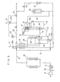
- Fig. 1 shows an embodiment of the present invention.
- the reference numeral 9 indicates an air compressor, 10 a drain separator, 11 a freon refrigerator, and 12 a couple of adsorbent columns.
- Each adsorbent column 12 is packed with a molecular sieve which adsorbs and remove H 2 0 and C0 2 from the compressed air from said air compressor 9.
- Indicated at 8 is a compressed air pipeline for feeding the compressed air freed of H 2 0 and C0 2 by adsorption.
- the numeral 13 indicates a first heat exchanger which is supplied with the compressed air freed of H 2 0 and C0 2 in the adsorbent column couple 12.
- To a second heat exchanger 14 is fed the compressed air from the first heat exchanger 13.
- the numeral 15 indicates a nitrogen distillation column, the top portion of which constitutes a partial condenser segment 21 having a condenser 21a, with the underneath portion constituting a column segment 22.
- the compressed air chilled to a cryogenic temperature in the first and second heat exchangers 13, 14 and fed via the pipeline 17 is further chilled and a portion thereof is liquefied and collects in the bottom of the column segment 22 as liquefied air 18 while nitrogen alone is pooled in gaseous state in the top ceiling portion of the column segment 22.
- a liquid nitrogen storage tank 23 contains liquid nitrogen (high-purity product) which is fed partly via a first feeding pipeline 24a into the top of the column segment 22 of the distillation column 15 for use as a refrigerant for the compressed air introduced into the column segment 22 and partly via a second feeding pipeline 24b into the first and second heat exchangers 14, 13 for heat exchange with the compressed air introduced into the heat exchangers 14, 13 to chill said air to a cryogenic temperature.
- the liquid nitrogen itself evaporates as a result of heat exchange in the heat exchangers 14, 13 and fed into a main pipeline 28 in the form of ordinary-temperature gas.
- the distillation column 15 is divided by a partitioning plate 20 into the partial condenser segment 21 and the column segment 22, and the condenser 21a in the partial condenser segment 21 is supplied with a portion of the nitrogen gas collected in the top portion of the column segment 22 via a pipeline 21b.
- the inside of this partial condenser segment 21 is relatively decompressed with respect to the inside of the column segment 22, and the liquefied air 18 (N 2 , 50-70%; 0 2 , 30-50%) pooled in the bottom of the column segment 22 is fed via a pipeline 19 equipped with an expansion valve 19a and gasified therein to lower the internal temperature to a level below the boiling point of liquid nitrogen.
- the nitrogen gas fed into the condenser 21a is liquefied.
- the top portion of the column segment 22 of the distillation column 15 is supplied with the liquid nitrogen produced in the condenser 21a of said partial condenser segment 21 via a down-coming pipeline 21c and also with liquid nitrogen from the liquid nitrogen storage tank 23 via the pipeline 24a.
- These two streams of liquid nitrogen flow down the column segment 22 from a liquid nitrogen basin 21d and come in counter-current contact with, and cool, the compressed air ascending from the bottom of the column segment 22 to thereby liquefy part of the compressed air.
- the high-boiling components in the compressed air are liquefied and collect in the bottom of the column segment 22, while nitrogen gas which is a low-boiling component collects in the top portion of the column segment 22.
- the reference numeral 27 indicates a withdrawal pipeline for withdrawing the nitrogen gas cooled in the top ceiling portion of the column segment 22 of the distillation column as product nitrogen gas. This pipeline guides the cryogenic nitrogen gas to the second and first exchangers 14, 13 for heat exchange with the compressed air fed thereto, and leads it at atmospheric temperature to a main pipeline 28.
- the withdrawal pipeline 27 is disposed to communicate at a substantial distance below the uppermost portion of the column segment 22 so that pure nitrogen gas free from He and H 2 may be withdrawn as product nitrogen gas.
- the reference numeral 29 indicates a pipeline for feeding gasified liquid air in the partial condenser segment 21 to the second and first heat exchangers 14, 13, with a pressure control valve thereof being indicated at 29a.
- the numeral 30 indicates a backup system line which, in the event of a failure of the air compression line, evaporates the liquid nitrogen in the liquid nitrogen storage tank 23 by means of an evaporator 31 and feeds it to the main pipeline 28 so as to prevent interruption of nitrogen gas supply.
- Indicated at 32 is an impurity analyzer which analyzes the purity of product nitrogen gas going out into the main pipeline 28 and, when the purity is low, actuates valves 34 and 34a to let off the product nitrogen gas in the direction indicated by the arrow- mark B.
- the equipment described above produces product nitrogen gas in the following manner.
- the air compressor 9 compresses the material air and the drain separator 10 removes water from the compressed air.
- the freon refrigerator 11 chills the compressed air and the chilled air is fed to the adsorption columns 12, where H 2 0 and C0 2 in the air are adsorbed and removed.
- This compressed air freed of H 2 0 and C0 2 is fed to the first and second heat exchangers 13, 14 which have been cooled by the liquid nitrogen supplied from the liquid nitrogen storage tank 23 via the second feeding pipeline 24b and the product nitrogen gas supplied from the distillation column 15 via the pipeline 27, etc., where it is chilled to a cryogenic temperature.
- the chilled air is then directly charged into a lower portion of the column segment 22 of the distillation column.
- This charged compressed air is chilled by contact with the liquid nitrogen fed into the column segment 22 from the liquid nitrogen storage tank 23 and the liquid nitrogen overflowing the liquid nitrogen basin 21d, whereby a portion of the air is liquefied and collects as liquid air 18 in the bottom of the column segment 22.
- oxygen which is a high-boiling fraction in the compressed air is liquefied while nitrogen remains as a gas.
- this remaining gaseous nitrogen is withdrawn through the withdrawal pipeline 27 and fed to the second and first heat exchangers 14, 13, where it is heated to a temperature near atmospheric temperature.
- This nitrogen is withdrawn from the main pipe 28 as product nitrogen gas.
- that portion of liquid nitrogen as fed to the column segment 22 from the liquid nitrogen storage tank 23 via the first feeding pipeline 24a serves as a refrigerant for liquefying the compressed air and the nitrogen itself vaporizes and is withdrawn as a part of product nitrogen gas via the withdrawal pipeline 27.
- the liquid nitrogen fed to the second and first heat exchangers 14, 13 from the liquid nitrogen storage tank 23 via the second feeding pipeline 24b serves as a refrigerant for cooling,the heat exchangers and said nitrogen itself vaporizes and is sent into the main pipeline 28 so as to constitute a part of product nitrogen gas.
- liquid nitrogen from the liquid nitrogen storage tank 23 is not discarded after use thereof as a refrigerant for the heat exchangers 14, 13 but is combined with the high-purity nitrogen gas produced from the raw material compressed air to give a product, so that it is used economically.
- Fig. 2 is shown an embodiment wherein a nitrogen distillation column differing in type from the nitrogen distillation column in the equipment of Fig. 1 is used in place of the latter.
- the partial condenser segment 21 is separated from the column segment 22 by means of partitioning plates 20 provided with a number of pipes 20a.
- liquid nitrogen from the liquid nitrogen storage tank 23 and this chills the compressed air supplied into the column segment 22 via the piping 19 in the pipes 20a of the partitioning plates 20, whereby oxygen in the compressed air is liquefied and falls while nitrogen alone is withdrawn in gaseous form from the top of the partial condenser segment 21.
- the internal pressure is lower as compared with the distillation column 15 in Fig. 1, so that the pressure of product nitrogen gas also becomes lower accordingly.
- Fig. 3 shows an embodiment wherein a distillation column of a still different type is used in lieu of the distillation column shown in Fig. 1.
- this distillation column 15 one column body is divided into two segments, namely the upper partial condenser segment 21 and the lower column segment 22.
- the partial condenser segment 21 there is provided a partial condenser 21a, to which the liquid air collecting in the bottom of the column segment 22 is supplied via the pipeline 19, while the liquid nitrogen from the liquid nitrogen storage tank 23 is supplied as reflux to the upper part of the column segment 22 via the first feeding pipeline 24a.
- this distillation column 15 produces low-pressure product nitrogen gas.
- Fig. 4 shows an embodiment wherein the equipment of Fig. 1 is provided with a temperature sensor, an adsorption column and a vaccum cold housing.
- a temperature sensor T is provided at the end, on the side of main pipeline 28, of the second feeding pipeline 24b.
- a valve provided at the end on the side of liquid nitrogen storage tank 23 is controlled, whereby the rate of flow of liquid nitrogen is controlled.
- an oxygen adsorption column 27a is provided in the withdrawal pipeline 27 to further increase the purity of product nitrogen gas by removing impurity oxygen, etc. in the cryogenic-temperature nitrogen gas discharged from the distillation column 15.
- the nitrogen distillation column 15, the first and second heat exchangers 13, 14 and the oxygen adsorption column 27a are accommodated in a vacuum cold housing (indicated in dot-dash line) for enhancement of distillation efficiency. Otherwise, this equipment is identical with the equipment illustrated in Fig. 1.
- the above oxygen adsorption column 27a is now described in further detail.
- This oxygen adsorption column 27a is packed with synthetic zeolite 3A, 4A or 5A having a pore size of 3 ⁇ , 4 ⁇ or 5 ⁇ , respectively (Union Carbide's molecular sieve 3A,. 4A or 5A). As shown in Fig.
- the synthetic zeolite 3A, 4A or 5A selectively adsorbs only oxygen and carbon monoxide at cryogenic temperatures of about -150°C.
- Union Carbide's synthetic zeolite 13X may also be used in place of the above-mentioned synthetic zeolite 3A, 4A or 5A. In this manner, oxygen and carbon monoxide alone are selectively adsorbed in the temperature range of about -150°C, so that the cryogenic nitrogen gas becomes highly pure.
- Fig. 6 shows an embodiment wherein a condenser is disposed in the column segment of the nitrogen distillation column in the equipment illustrated in Fig. 1, with a level guage also disposed on the periphery.
- a condenser 22a is disposed in the column segment 22 of the nitrogen distillation column 15 and liquid nitrogen is fed to said condenser as a refrigerant from the liquid nitrogen storage tank 23 via the first feeding line 24a to chill the compressed air entering the column segment 22 at the lower part thereof and ascending in the column segment 22.
- High-boiling components, such as oxygen, thus liquefied are retained in the bottom of the column segment 22, while low-boiling nitrogen gas is collected in the upper part of the column segment 22.
- the vaporized liquid nitrogen after serving as refrigerant in the condenser 22a is led to a discharge pipeline 24'b and, after heat exchange in the second and first heat exchangers 14, 13, let out from the system. Furthermore, a level gauge 25 is provided on the periphery of the partial condenser segment 21 of the distillation column 15 and at the same time the first feeding pipeline 24a is equipped with a valve means 26 so that the rate of feeding of liquid nitrogen from the liquid nitrogen storage tank 23 can be controlled by controlling the valve 26 depending on the level of liquid air in the partial condenser segment 21. Otherwise, this equipment is identical with the equipment illustrated in Fig. 1.
- Fig. 7 shows a modification of the equipment shown in Fig. 3.
- the liquid nitrogen fed to the second and first heat exchangers 14, 13 from the liquid nitrogen storage tank 23 via the second feeding pipeline 24b is led to the main piping 28, such nitrogen is released into the atmosphere in the equipment shown in Fig. 7.
- Fig. 8 shows an embodiment wherein an oxygen distillation column is added to the equipment of Fig. 1.
- the numeral 40 indicates an oxygen distillation column, which is connected to the bottom of the partial condenser segment 21 of the nitrogen distillation column 15 by means of a liquid air feeding pipeline 41.
- the liquid air introduced into the partial condenser segment 21 is then withdrawn into said oxygen distllation column taking advantage of head difference and, in said column, nitrogen is removed by evaporation, with oxygen collected in liquid state in the bottom.
- the numeral 42 indicates a discharge pipeline for sending the used liquid nitrogen, now in gaseous state, into the discharge pipeline 29 for discharging the vaporized liquid nitrogen in admixture with the vaporized liquid air.
- a withdrawal pipeline 43 for withdrawing the liquid oxygen retained in the bottom of the oxygen distillation column 40 leads said liquid oxygen to the second heat exchanger 14 and, after heat exchange with the compressed air fed through a branched pipe 9' and gasification due to temperature rise, further to a product oxygen withdrawal pipeline 44.
- a compressed air transfer pipeline 45 extends from the second heat exchanger 14 to the pipeline 17. On its way, said pipeline 45 passes through the oxygen distallation column 40, whereby the compressed air can heat the liquid oxygen collected in the bottom of said column to thereby vaporize the same. The vaporized oxygen comes into countercurrent contact with the liquid air falling from the pipe 41 through the column 40, so that the rectification efficiency can be improved.
- the numeral 25 indicates a level gauge and 26 a valve means controlled by said gauge. Otherwise, this equipment is identical with the equipment depicted in Fig. 1.
- high-purity product oxygen gas can be obtained in an efficient manner since product oxygen gas is produced by feeding oxygen-rich liquid air 18 obtained after nitrogen gas separation to the oxygen distillation column 40 via the partial condenser segment 21 of the nitrogen distillation column 15 to thereby remove residual nitrogen from the liquid air 18 by evaporation and evaporating the thus-obtained liquid oxygen in the heat exchanger 14.
- this equipment can produce not only high-purity nitrogen gas but also high-purity oxygen gas with high efficiency.
- Fig. 9 shows a modification of the equipment of Fig. 8.
- this equipment uses another distillation column shown in Fig. 2 in place of the distillation column shown in Fig. 8.
- the liquid air 18 retained in the bottom 22 of the distillation column 15 is fed to the oxygen distillation column 40 via a pipeline 41. Otherwise, this equipment is substantially identical with the equipment shown in Fig. 8.
- the oxygen distillation column 40 and the partial condenser segment 21 of the nitrogen distillation column 15 communicate with each other as a result of connection of the discharge pipe 42 to the vaporized liquid air discharge pipeline 29, the discharge pipeline 42 may be independent of the vaporized liquid air discharge pipeline 29 without connecting them to each other, as shown in Fig. 11.
- the oxygen distillation column 40 and nitrogen distillation column 15 are put in mutually independent state, so that the production quantity of oxygen gas can be increased or decreased without being substantially influenced by the production quantity of nitrogen gas in the nitrogen distillation column 15.
- adsorption column 43a packed with a hydrocarbon adsorbent such as silica gel or alumina gel to the liquid oxygen withdrawal pipeline 43 shown in Fig. 8 so that impurity hydrocarbons contained in liquid oxygen can be removed in the mode of liquid phase adsorption.
- a hydrocarbon adsorbent such as silica gel or alumina gel
- Fig. 13 shows an embodiment wherein the vaporized liquid air discharge pipeline 29 is provided, at the open end thereof, with a plurality of nitrogen adsorption columns for obtaining oxygen gas from the vaporized liquid air.
- the numerals 40', 41' and 42' each indicates an adsorption column packed with an adsorbent (synthetic zeolite: molecular sieve) capable of adsorbing N 2 selectively and the columns are connected, at the entrance thereof, to said discharge pipeline 29 via inlet lines 40a, 41a and 42a provided with valves 40b, 41b and 42b, respectively.
- adsorbent synthetic zeolite: molecular sieve
- a vacuum pump 44' is connected to the entrance of each of said adsorption columns 40', 41' and 42' via a suction pipeline 43' and via suction pipelines 40c, 41c and 42c, respectively.
- Withdrawal pipelines 40d, 41d and 42d are connected to said adsorption columns 40', 41' and 42', respectively, at the outlet thereof, and are provided with valves 40e, 41e and 42e, respectively.
- These withdrawal pipelines 40d, 41d and 42d are connected to a buffer tank 46' via a product oxygen gas withdrawal pipeline 45'. While one of said adsorption columns 40', 41' and 42' is used for adsorption, the remaining columns are regenerated by suction by the vacuum pump 44'.
- the numeral 25 indicates a level gauge and 26 a valve controlled by said gauge. Otherwise, this equipment is substantially identical with the equipment shown in Fig. 1.
- the oxygen-rich liquid air 18 after separation of nitrogen gas is fed to the partial condenser segment 21 of the nitrogen distillation column 15 to chill the condenser 21a and oxygen-rich liquid air vapor formed there is not released as it is into the air but is introduced into the adsorption column 40', (41'), (42') to remove residual nitrogen by adsorption and thus produce product oxygen gas. Therefore, high-purity product oxygen gas can be obtained efficiently.
- this equipment can produce not only high-purity nitrogen gas but also high-purity oxygen gas efficiently.
- Fig. 14 shows a modification of the equipment of Fig. 13.
- this equipment uses the distillation column shown in Fig. 2 in place of the distillation column shown inFig. 13.
- the structure of the distillation column 15 allows the liquid air 18 retained in the bottom of the column segment 22 of the distillation column 15 to be fed to the adsorption column 40', (41'), (42') via the vaporized liquid air discharge pipeline 29 after vaporization upon passing through the heat exchanger 13.
- this equipment is substantially indentical with the equipment illustrated in Fig. 13.
Abstract
Description
- The present invention relates to a production equipment for high-purity nitrogen gas.
- While the electronics industry consumes a very large quantity of nitrogen gas, stringent requirements have been imposed on the purity of the nitrogen gas they use from the standpoint of maintenance of the high precision of parts. Nitrogen gas is generally produced from air in a production sequnece which consists of compressing the air with a compressor, passing the compressed air through an adsorbent column to remove carbon dioxide gas and water, feeding the emerging air further to a heat exchanger where it is chilled by heat exchange with a refrigerant, feeding the chilled air to a distillation column for cryogenic liquefaction and separation to give product nitrogen gas, and finally passing the same through said heat exchanger to heat it up to a temperature near atmospheric temperature. However, the product nitrogen gas thus produced contains oxygen as an impurity and the use of this nitrogen gas as it is presents various problems. One of the methods for removing impurity oxygen (1) comprises adding a small amount of hydrogen to nitrogen gas and reacting the hydrogen in the mixture with the impurity oxygen in the nitrogen gas in the presence of a platinum catalyst at a temperature of about 200°C to remove the impurity oxygen in the form of water. Another method (2) comprises contacting nitrogen gas with a nickel catalyst at a temperature of about 200°C to remove the impurity oxygen by way of the reaction Ni + 1/202 + NiO. However, as both methods involve the step of heating nitrogen gas to a high temperature for catalytic reaction, the corresponding hardware cannot be built into the nitrogen gas production line which is a cryogenic system. That is to say, the purification equipment must be installed independently of the nitrogen gas production equipment and this entails, of necessity, the disadvantage that the overall size of the production plant is increased. Furthermore, the first-mentioned method (1) requires exact control over the addition level of hydrogen. Unless hydrogen is added in an amount exactly commensurate with the amount of impurity oxygen present, either some oxygen remains in the product gas or the very hydrogen so added becomes a new impurity, so that high skill is required in operation. In the second-mentioned method (2), the NiO produced in the reaction with impurity oxygen must be regenerated (NiO + H2 + Ni + H20) and the cost of the H2 gas equipment for catalyst regeneration contributes to an increased purification cost. Solutions to these problems have been awaited.
- Furthermore, the conventional nitrogen gas production equipment employs an expansion turbine for chilling the refrigerant used for heat exchange with compressed air from the compressor and this turbine is driven by the pressure of the gas generated by gasification of the liquid air collecting in the distillation column (As the result of cryogenic liquefaction and separation, the low-boiling nitrogen leaves the column, while the balance in the form of an oxygen-rich liquid air collects in the column). However, the expansion turbine has a high rotational speed (the order of tens of thousand revolutions per minute) and cannot easily follow a variation in load, thus requiring a specially trained operator. Moreover, as a high-speed machine, the expansion turbine not only demands high-precision in construction and is costly but requires specially trained personnel for its operation. These problems emanate all from the high-speed rotary mechanism of the expansion turbine and there has been a strong demand for elimination of the expansion turbine having such a high-speed rotary mechanism. Furthermore, an equipment capable of producing oxygen gas as well as nitrogen gas with the expansion turbine eliminated, if such becomes available, will be convenient since one single equipment can produce nitrogen gas and oxygen gas.
- It is a primary object of the present invention to provide a high-purity nitrogen gas production equipment which requires neither an expansion turbine nor a purification system. A further object is to provide a high-purity nitrogen gas production equipment which can also produce oxygen gas simultaneously.
- Developed for the purpose of accomplishing the above-mentioned object, the present invention provides a high-purity nitrogen gas production equipment which comprises, in one aspect, an air compression means for compressing the air from an external environment, an elimination means for eliminating carbon dioxide gas and water from the compressed air, a heat exchange means for chilling the compressed air from said elimination means to a cryogenic temperature, a nitrogen distillation column adapted to liquefy a portion of the cryogenic compressed air from said heat exchange means and collect the same therein while retaining nitrogen alone in gaseous form, a liquid nitrogen storage means for storing liquid nitrogen, a first feeding pipeline for leading liquid nitrogen in said liquid nitrogen storage means to said nitrogen distillation column for use as a refrigerant, a second feeding pipeline for leading liquid nitrogen in said liquid nitrogen storage means to said heat exchange means for use as a refrigerant for said heat exchange means and a nitrogen gas withdrawal line for withdrawing the retained gaseous nitrogen from said nitrogen distillation column as product nitrogen gas. In accordance with a second aspect of the invention, said equipment further comprises a means for improving the purity of product nitrogen gas as provided in the nitrogen gas withdrawal line for withdrawing the product nitrogen gas from said nitrogen distillation column, said means being an adsorption means containing an adsorbent capable of selectively adsorbing oxygen and carbon monoxide at cryogenic temperatures. In accordance with a third aspect of the invention, said equipment additionally comprises an oxygen distillation column disposed separately from said nitrogen distillation column, whereby oxygen gas can also be produced besides nitrogen by feeding oxygen-rich liquid air remaining after separation of nitrogen gas from said nitrogen distillation column to said oxygen distillation column. In accordance with a fourth aspect of the invention, said equipment avoids the use of such oxygen distillation column according to said third aspect but employs an adsorption tube or column containing an adsorbent capable of selectively adsorbing nitrogen as disposed in a discharge line extending from said nitrogen distillation column [for discharging oxygen-rich liquid air (or vapor thereof) after separation of nitrogen gas into the exterior] to thereby remove nitrogen fraction from the oxygen-rich liquid air passing said discharge line so as to convert the latter to oxygen gas, said equipment thus producing oxygen gas in addition to nitrogen gas obtained from said nitrogen distillaion column.
- The high-purity nitrogen gas production equipment according to the present invention does not employ an expansion turbine but, instead, employs a liquid nitrogen storage means such as a liquid nitrogen storage tank having no rotary element and, therefore, the whole equipment has no revolving parts and, hence, is trouble-free. Furthermore, whereas the expansion turbine is costly, the liquid nitrogen tank is not expensive and does not require special personnel for operation. In addition, the expansion turbine (which is driven by the pressure of the gas generated from the liquefied air collected within the nitrogen distillation column) is driven at a very high speed (the order of tens of thousand revolutions per minute), it is difficult to follow a delicate variation in load (the variation in the rate of withdrawal of product nitrogen gas). Therefore, it is difficult to accurately vary the supply of liquefied air to the expansion turbine according to the change in the outgoing product nitrogen gas so as to chill the compressed air, which is the raw material for nitrogen gas, to a constant temperature at all times. As a consequence, the product nitrogen gas varies in purity so that low-purity products may be withdrawn from time to time to affect the overall quality of production.
- In contrast, as the equipment according to the present invention employs a liquid nitrogen storage tank, in lieu of the expansion turbine, and liquid nitrogen, which permits delicate control of feed, as a refrigerant for both the heat exchange means such as a heat exchanger and the nitrogen distillation column, the equipment allows for delicate follow-up of load variation and, thus, enables one to produce nitrogen gas of extremely high and uniform purity. This, in turn, enables one to dispense with the purification system heretofore required. Furthermore, said equipment does not waste resources since liquid nitrogen is used as a refrigerant and, after use, made up into product nitrogen gas together with nitrogen gas produced by using air as the raw material, without allowing escape thereof. The equipment according to the second aspect of the invention, which has, in the product nitrogen gas withdrawal line of the equipment according to the first aspect of the invention, an adsorption means containing an adsorbent capable of selectively adsorbing oxygen and carbon monoxide at cryogenic temperatures, produces further improvement in the purity of product nitrogen gas as a result of adsorptive removal of impurity oxygen and so on contained therin. In the equipment according to the third aspect of the invention, an oxygen distillation column is used additionally in the equipment according to the above first aspect to thereby produce oxygen gas by feeding oxygen-rich liquid air after separation of nitrogen gas from the nitrogen distillation column to the oxygen distillation column, so that oxygen gas can be produced efficiently. In this way, this equipment by itself can produce high-purity nitrogen gas and oxygen gas efficiently and thus is best suited for use in the electronics industry. Furthermore, in the equipment according to the fourth aspect of the invention, in which an adsorption tube or column containing an adsorbent capable of adsorbing nitrogen selectively is disposed in the discharge line extending from the nitrogen distillation column [for discharging oxygen-rich liquid air (or vapor thereof) after separation of nitrogen gas into the exterior] to thereby removing nitrogen portion from the oxygen-rich liquid air flowing in said discharge line so as to give oxygen gas to be withdrawn as product oxygen gas, so that said equipment can readily produce oxygen gas with relatively high purity although the purity of oxygen gas is somewhat inferior as compared with the equipment according to the third aspect mentioned above. In this way, also the equipment according to the fourth aspect can produce both of high-purity nitrogen gas and oxygen gas having relatively high purity.
-
- Fig. 1 is a schematic process diagram showing one embodiment of the present invention;
- Fig. 2 and Fig. 3 each is a schematic process diagram showing a modification thereof;
- Fig. 4 is a schematic process diagram showing another embodiment;
- Fig. 5 shows adsorption characteristic curves for an adsorbent;
- Fig. 6 is a schematic process diagram showing still another embodiment;
- Fig. 7 is a schematic process diagram showing a modification of the embodiment shown in Fig. 3;
- Fig. 8-12 each is a schematic process diagram showing an embodiment in which an oxygen distillation column is used additionally; and
- Fig. 13 and Fig. 14 each is a schematic process diagram showing an embodiment in which a nitrogen adsorption tube is used.
- The present invention will be described in detail with reference to its embodiments.
- Fig. 1 shows an embodiment of the present invention. In Fig. 1, the
reference numeral 9 indicates an air compressor, 10 a drain separator, 11 a freon refrigerator, and 12 a couple of adsorbent columns. Eachadsorbent column 12 is packed with a molecular sieve which adsorbs and removeH 20 and C02 from the compressed air from saidair compressor 9. Indicated at 8 is a compressed air pipeline for feeding the compressed air freed ofH 20 and C02 by adsorption. Thenumeral 13 indicates a first heat exchanger which is supplied with the compressed air freed ofH 20 and C02 in theadsorbent column couple 12. To asecond heat exchanger 14 is fed the compressed air from thefirst heat exchanger 13. Thenumeral 15 indicates a nitrogen distillation column, the top portion of which constitutes apartial condenser segment 21 having acondenser 21a, with the underneath portion constituting acolumn segment 22. - In the distillation column, the compressed air chilled to a cryogenic temperature in the first and
second heat exchangers pipeline 17 is further chilled and a portion thereof is liquefied and collects in the bottom of thecolumn segment 22 as liquefiedair 18 while nitrogen alone is pooled in gaseous state in the top ceiling portion of thecolumn segment 22. A liquidnitrogen storage tank 23 contains liquid nitrogen (high-purity product) which is fed partly via afirst feeding pipeline 24a into the top of thecolumn segment 22 of thedistillation column 15 for use as a refrigerant for the compressed air introduced into thecolumn segment 22 and partly via asecond feeding pipeline 24b into the first andsecond heat exchangers heat exchangers heat exchangers main pipeline 28 in the form of ordinary-temperature gas. The-above-mentioneddistillation column 15 is now described in detail. Thedistillation column 15 is divided by apartitioning plate 20 into thepartial condenser segment 21 and thecolumn segment 22, and thecondenser 21a in thepartial condenser segment 21 is supplied with a portion of the nitrogen gas collected in the top portion of thecolumn segment 22 via apipeline 21b. The inside of thispartial condenser segment 21 is relatively decompressed with respect to the inside of thecolumn segment 22, and the liquefied air 18 (N2, 50-70%; 02, 30-50%) pooled in the bottom of thecolumn segment 22 is fed via apipeline 19 equipped with anexpansion valve 19a and gasified therein to lower the internal temperature to a level below the boiling point of liquid nitrogen. As the result of this chilling, the nitrogen gas fed into thecondenser 21a is liquefied. The top portion of thecolumn segment 22 of thedistillation column 15 is supplied with the liquid nitrogen produced in thecondenser 21a of saidpartial condenser segment 21 via a down-comingpipeline 21c and also with liquid nitrogen from the liquidnitrogen storage tank 23 via thepipeline 24a. These two streams of liquid nitrogen flow down thecolumn segment 22 from aliquid nitrogen basin 21d and come in counter-current contact with, and cool, the compressed air ascending from the bottom of thecolumn segment 22 to thereby liquefy part of the compressed air. In this process, the high-boiling components in the compressed air are liquefied and collect in the bottom of thecolumn segment 22, while nitrogen gas which is a low-boiling component collects in the top portion of thecolumn segment 22. Thereference numeral 27 indicates a withdrawal pipeline for withdrawing the nitrogen gas cooled in the top ceiling portion of thecolumn segment 22 of the distillation column as product nitrogen gas. This pipeline guides the cryogenic nitrogen gas to the second andfirst exchangers main pipeline 28. In this connection, since low-boiling He (-269°C) and H2 (-253°C) tend to collect, together with nitrogen gas, in the uppermost portion of thecolumn segment 22 of the distillation column, thewithdrawal pipeline 27 is disposed to communicate at a substantial distance below the uppermost portion of thecolumn segment 22 so that pure nitrogen gas free from He and H2 may be withdrawn as product nitrogen gas. Thereference numeral 29 indicates a pipeline for feeding gasified liquid air in thepartial condenser segment 21 to the second andfirst heat exchangers nitrogen storage tank 23 by means of anevaporator 31 and feeds it to themain pipeline 28 so as to prevent interruption of nitrogen gas supply. Indicated at 32 is an impurity analyzer which analyzes the purity of product nitrogen gas going out into themain pipeline 28 and, when the purity is low, actuatesvalves - The equipment described above produces product nitrogen gas in the following manner. Thus, the
air compressor 9 compresses the material air and thedrain separator 10 removes water from the compressed air. Thefreon refrigerator 11 chills the compressed air and the chilled air is fed to theadsorption columns 12, whereH 20 and C02 in the air are adsorbed and removed. This compressed air freed ofH 20 and C02 is fed to the first andsecond heat exchangers nitrogen storage tank 23 via thesecond feeding pipeline 24b and the product nitrogen gas supplied from thedistillation column 15 via thepipeline 27, etc., where it is chilled to a cryogenic temperature. The chilled air is then directly charged into a lower portion of thecolumn segment 22 of the distillation column. This charged compressed air is chilled by contact with the liquid nitrogen fed into thecolumn segment 22 from the liquidnitrogen storage tank 23 and the liquid nitrogen overflowing theliquid nitrogen basin 21d, whereby a portion of the air is liquefied and collects asliquid air 18 in the bottom of thecolumn segment 22. In this process, due to the difference between nitrogen and oxygen in boiling point (boiling point of oxygen -183°C; boiling point of nitrogen -196°C), oxygen which is a high-boiling fraction in the compressed air is liquefied while nitrogen remains as a gas. Then, this remaining gaseous nitrogen is withdrawn through thewithdrawal pipeline 27 and fed to the second andfirst heat exchangers main pipe 28 as product nitrogen gas. In this process, that portion of liquid nitrogen as fed to thecolumn segment 22 from the liquidnitrogen storage tank 23 via thefirst feeding pipeline 24a serves as a refrigerant for liquefying the compressed air and the nitrogen itself vaporizes and is withdrawn as a part of product nitrogen gas via thewithdrawal pipeline 27. The liquid nitrogen fed to the second andfirst heat exchangers nitrogen storage tank 23 via thesecond feeding pipeline 24b serves as a refrigerant for cooling,the heat exchangers and said nitrogen itself vaporizes and is sent into themain pipeline 28 so as to constitute a part of product nitrogen gas. In this way, the liquid nitrogen from the liquidnitrogen storage tank 23 is not discarded after use thereof as a refrigerant for theheat exchangers - In Fig. 2 is shown an embodiment wherein a nitrogen distillation column differing in type from the nitrogen distillation column in the equipment of Fig. 1 is used in place of the latter. Thus, in this
distillation column 15, thepartial condenser segment 21 is separated from thecolumn segment 22 by means of partitioningplates 20 provided with a number ofpipes 20a. Into thispartial condenser segment 21 is fed liquid nitrogen from the liquidnitrogen storage tank 23 and this chills the compressed air supplied into thecolumn segment 22 via the piping 19 in thepipes 20a of thepartitioning plates 20, whereby oxygen in the compressed air is liquefied and falls while nitrogen alone is withdrawn in gaseous form from the top of thepartial condenser segment 21. In thisnitrogen distillation column 15, the internal pressure is lower as compared with thedistillation column 15 in Fig. 1, so that the pressure of product nitrogen gas also becomes lower accordingly. - Fig. 3 shows an embodiment wherein a distillation column of a still different type is used in lieu of the distillation column shown in Fig. 1. Thus, in this
distillation column 15, one column body is divided into two segments, namely the upperpartial condenser segment 21 and thelower column segment 22. Within thepartial condenser segment 21, there is provided apartial condenser 21a, to which the liquid air collecting in the bottom of thecolumn segment 22 is supplied via thepipeline 19, while the liquid nitrogen from the liquidnitrogen storage tank 23 is supplied as reflux to the upper part of thecolumn segment 22 via thefirst feeding pipeline 24a. Like the distillation column shown in Fig. 2, thisdistillation column 15 produces low-pressure product nitrogen gas. - Fig. 4 shows an embodiment wherein the equipment of Fig. 1 is provided with a temperature sensor, an adsorption column and a vaccum cold housing. Thus, in this embodiment, a temperature sensor T is provided at the end, on the side of
main pipeline 28, of thesecond feeding pipeline 24b. By means of the output signal of this sensor T, a valve provided at the end on the side of liquidnitrogen storage tank 23 is controlled, whereby the rate of flow of liquid nitrogen is controlled. In addition, anoxygen adsorption column 27a is provided in thewithdrawal pipeline 27 to further increase the purity of product nitrogen gas by removing impurity oxygen, etc. in the cryogenic-temperature nitrogen gas discharged from thedistillation column 15. Furthermore, thenitrogen distillation column 15, the first andsecond heat exchangers oxygen adsorption column 27a are accommodated in a vacuum cold housing (indicated in dot-dash line) for enhancement of distillation efficiency. Otherwise, this equipment is identical with the equipment illustrated in Fig. 1. The aboveoxygen adsorption column 27a is now described in further detail. Thisoxygen adsorption column 27a is packed with synthetic zeolite 3A, 4A or 5A having a pore size of 3Å, 4Å or 5 Å, respectively (Union Carbide's molecular sieve 3A,. 4A or 5A). As shown in Fig. 5, the synthetic zeolite 3A, 4A or 5A selectively adsorbs only oxygen and carbon monoxide at cryogenic temperatures of about -150°C. Union Carbide's synthetic zeolite 13X may also be used in place of the above-mentioned synthetic zeolite 3A, 4A or 5A. In this manner, oxygen and carbon monoxide alone are selectively adsorbed in the temperature range of about -150°C, so that the cryogenic nitrogen gas becomes highly pure. - Fig. 6 shows an embodiment wherein a condenser is disposed in the column segment of the nitrogen distillation column in the equipment illustrated in Fig. 1, with a level guage also disposed on the periphery. Thus, in this equipment, a
condenser 22a is disposed in thecolumn segment 22 of thenitrogen distillation column 15 and liquid nitrogen is fed to said condenser as a refrigerant from the liquidnitrogen storage tank 23 via thefirst feeding line 24a to chill the compressed air entering thecolumn segment 22 at the lower part thereof and ascending in thecolumn segment 22. High-boiling components, such as oxygen, thus liquefied are retained in the bottom of thecolumn segment 22, while low-boiling nitrogen gas is collected in the upper part of thecolumn segment 22. The vaporized liquid nitrogen after serving as refrigerant in thecondenser 22a is led to a discharge pipeline 24'b and, after heat exchange in the second andfirst heat exchangers level gauge 25 is provided on the periphery of thepartial condenser segment 21 of thedistillation column 15 and at the same time thefirst feeding pipeline 24a is equipped with a valve means 26 so that the rate of feeding of liquid nitrogen from the liquidnitrogen storage tank 23 can be controlled by controlling thevalve 26 depending on the level of liquid air in thepartial condenser segment 21. Otherwise, this equipment is identical with the equipment illustrated in Fig. 1. - Fig. 7 shows a modification of the equipment shown in Fig. 3. Thus, while, in the equipment of Fig. 3, the liquid nitrogen fed to the second and
first heat exchangers nitrogen storage tank 23 via thesecond feeding pipeline 24b is led to themain piping 28, such nitrogen is released into the atmosphere in the equipment shown in Fig. 7. - Fig. 8 shows an embodiment wherein an oxygen distillation column is added to the equipment of Fig. 1. In Fig. 8, the numeral 40 indicates an oxygen distillation column, which is connected to the bottom of the
partial condenser segment 21 of thenitrogen distillation column 15 by means of a liquidair feeding pipeline 41. The liquid air introduced into thepartial condenser segment 21 is then withdrawn into said oxygen distllation column taking advantage of head difference and, in said column, nitrogen is removed by evaporation, with oxygen collected in liquid state in the bottom. The numeral 42 indicates a discharge pipeline for sending the used liquid nitrogen, now in gaseous state, into thedischarge pipeline 29 for discharging the vaporized liquid nitrogen in admixture with the vaporized liquid air. Awithdrawal pipeline 43 for withdrawing the liquid oxygen retained in the bottom of theoxygen distillation column 40 leads said liquid oxygen to thesecond heat exchanger 14 and, after heat exchange with the compressed air fed through a branched pipe 9' and gasification due to temperature rise, further to a productoxygen withdrawal pipeline 44. A compressedair transfer pipeline 45 extends from thesecond heat exchanger 14 to thepipeline 17. On its way, saidpipeline 45 passes through theoxygen distallation column 40, whereby the compressed air can heat the liquid oxygen collected in the bottom of said column to thereby vaporize the same. The vaporized oxygen comes into countercurrent contact with the liquid air falling from thepipe 41 through thecolumn 40, so that the rectification efficiency can be improved. The numeral 25 indicates a level gauge and 26 a valve means controlled by said gauge. Otherwise, this equipment is identical with the equipment depicted in Fig. 1. - In this equipment, high-purity product oxygen gas can be obtained in an efficient manner since product oxygen gas is produced by feeding oxygen-rich
liquid air 18 obtained after nitrogen gas separation to theoxygen distillation column 40 via thepartial condenser segment 21 of thenitrogen distillation column 15 to thereby remove residual nitrogen from theliquid air 18 by evaporation and evaporating the thus-obtained liquid oxygen in theheat exchanger 14. In this way, this equipment can produce not only high-purity nitrogen gas but also high-purity oxygen gas with high efficiency. - Fig. 9 shows a modification of the equipment of Fig. 8. Thus, this equipment uses another distillation column shown in Fig. 2 in place of the distillation column shown in Fig. 8. In this equipment, owing to the structure of the
distillation column 15, theliquid air 18 retained in the bottom 22 of thedistillation column 15 is fed to theoxygen distillation column 40 via apipeline 41. Otherwise, this equipment is substantially identical with the equipment shown in Fig. 8. - Whereas, in the embodiments shown in Fig. 8 and Fig. 9, the liquid oxygen retained in the bottom of the
oxygen distillation column 40 is withdrawn, it is also possible to withdraw oxygen in vaporized state, pass the same through thesecond heat exchanger 14 and then withdraw it via the productoxygen withdrawal pipeline 44, as shown in Fig. 10. It is further possible to accommodate thedistillation columns heat exchangers - Whereas, in the equipments shown in Fig. 8 and Fig. 10, the
oxygen distillation column 40 and thepartial condenser segment 21 of thenitrogen distillation column 15 communicate with each other as a result of connection of thedischarge pipe 42 to the vaporized liquidair discharge pipeline 29, thedischarge pipeline 42 may be independent of the vaporized liquidair discharge pipeline 29 without connecting them to each other, as shown in Fig. 11. By this measure, theoxygen distillation column 40 andnitrogen distillation column 15 are put in mutually independent state, so that the production quantity of oxygen gas can be increased or decreased without being substantially influenced by the production quantity of nitrogen gas in thenitrogen distillation column 15. - Furthermore, as illustrated in Fig. 12, it is possible to add an
adsorption column 43a packed with a hydrocarbon adsorbent such as silica gel or alumina gel to the liquidoxygen withdrawal pipeline 43 shown in Fig. 8 so that impurity hydrocarbons contained in liquid oxygen can be removed in the mode of liquid phase adsorption. - Fig. 13 shows an embodiment wherein the vaporized liquid
air discharge pipeline 29 is provided, at the open end thereof, with a plurality of nitrogen adsorption columns for obtaining oxygen gas from the vaporized liquid air. In the figure, the numerals 40', 41' and 42' each indicates an adsorption column packed with an adsorbent (synthetic zeolite: molecular sieve) capable of adsorbing N2 selectively and the columns are connected, at the entrance thereof, to saiddischarge pipeline 29 viainlet lines valves suction pipelines Withdrawal pipelines valves withdrawal pipelines - In this equipment, the oxygen-rich
liquid air 18 after separation of nitrogen gas is fed to thepartial condenser segment 21 of thenitrogen distillation column 15 to chill thecondenser 21a and oxygen-rich liquid air vapor formed there is not released as it is into the air but is introduced into the adsorption column 40', (41'), (42') to remove residual nitrogen by adsorption and thus produce product oxygen gas. Therefore, high-purity product oxygen gas can be obtained efficiently. Thus, this equipment can produce not only high-purity nitrogen gas but also high-purity oxygen gas efficiently. - Fig. 14 shows a modification of the equipment of Fig. 13. Thus, this equipment uses the distillation column shown in Fig. 2 in place of the distillation column shown inFig. 13. In this equipment, the structure of the
distillation column 15 allows theliquid air 18 retained in the bottom of thecolumn segment 22 of thedistillation column 15 to be fed to the adsorption column 40', (41'), (42') via the vaporized liquidair discharge pipeline 29 after vaporization upon passing through theheat exchanger 13. Otherwise, this equipment is substantially indentical with the equipment illustrated in Fig. 13.
Claims (6)
Applications Claiming Priority (2)
| Application Number | Priority Date | Filing Date | Title |
|---|---|---|---|
| JP146331/84 | 1984-07-13 | ||
| JP14633184A JPS6124967A (en) | 1984-07-13 | 1984-07-13 | Production unit for high-purity nitrogen gas |
Publications (3)
| Publication Number | Publication Date |
|---|---|
| EP0190355A1 true EP0190355A1 (en) | 1986-08-13 |
| EP0190355A4 EP0190355A4 (en) | 1986-11-26 |
| EP0190355B1 EP0190355B1 (en) | 1989-01-25 |
Family
ID=15405266
Family Applications (1)
| Application Number | Title | Priority Date | Filing Date |
|---|---|---|---|
| EP85903387A Expired EP0190355B1 (en) | 1984-07-13 | 1985-07-08 | Apparatus for producing high-purity nitrogen gas |
Country Status (6)
| Country | Link |
|---|---|
| US (1) | US4668260A (en) |
| EP (1) | EP0190355B1 (en) |
| JP (1) | JPS6124967A (en) |
| KR (1) | KR890001744B1 (en) |
| DE (1) | DE3567960D1 (en) |
| WO (1) | WO1986000693A1 (en) |
Cited By (2)
| Publication number | Priority date | Publication date | Assignee | Title |
|---|---|---|---|---|
| FR2660741A1 (en) * | 1990-04-10 | 1991-10-11 | Air Liquide | PROCESS AND PLANT FOR GENERATING GASEOUS NITROGEN AND CORRESPONDING NITROGEN SUPPLY SYSTEM THEREFOR. |
| US8080198B2 (en) | 2006-10-20 | 2011-12-20 | Avery Dennison Corporation | Elastic diaper component |
Families Citing this family (17)
| Publication number | Priority date | Publication date | Assignee | Title |
|---|---|---|---|---|
| US5058387A (en) * | 1989-07-05 | 1991-10-22 | The Boc Group, Inc. | Process to ultrapurify liquid nitrogen imported as back-up for nitrogen generating plants |
| FR2670278B1 (en) * | 1990-12-06 | 1993-01-22 | Air Liquide | METHOD AND INSTALLATION FOR AIR DISTILLATION IN A VARIABLE REGIME FOR THE PRODUCTION OF GASEOUS OXYGEN. |
| US5144808A (en) * | 1991-02-12 | 1992-09-08 | Liquid Air Engineering Corporation | Cryogenic air separation process and apparatus |
| CN1071444C (en) * | 1992-02-21 | 2001-09-19 | 普拉塞尔技术有限公司 | Cryogenic air separation system for producing gaseous oxygen |
| FR2694383B1 (en) * | 1992-07-29 | 1994-09-16 | Air Liquide | Production and installation of nitrogen gas production with several different purities. |
| US5528906A (en) * | 1995-06-26 | 1996-06-25 | The Boc Group, Inc. | Method and apparatus for producing ultra-high purity oxygen |
| FR2753391B1 (en) * | 1996-09-16 | 1998-10-30 | Air Liquide | PURIFICATION OF A FLUID INERTED IN THE LIQUID STATE IN ITS H2 AND / OR CO IMPURITIES |
| TWI227531B (en) * | 1997-03-05 | 2005-02-01 | Hitachi Ltd | Manufacturing method of semiconductor integrated circuit device |
| US5740683A (en) * | 1997-03-27 | 1998-04-21 | Praxair Technology, Inc. | Cryogenic rectification regenerator system |
| EP1207362A1 (en) * | 2000-10-23 | 2002-05-22 | Air Products And Chemicals, Inc. | Process and apparatus for the production of low pressure gaseous oxygen |
| EP1582830A1 (en) * | 2004-03-29 | 2005-10-05 | Air Products And Chemicals, Inc. | Process and apparatus for the cryogenic separation of air |
| US7210312B2 (en) * | 2004-08-03 | 2007-05-01 | Sunpower, Inc. | Energy efficient, inexpensive extraction of oxygen from ambient air for portable and home use |
| EP1890099A1 (en) * | 2006-08-08 | 2008-02-20 | Linde Aktiengesellschaft | Dephlegmator |
| US7981195B2 (en) | 2007-11-09 | 2011-07-19 | Praxair Technology, Inc. | System for preventing contaminants from reaching a gas purifier |
| CN102448570B (en) * | 2009-05-21 | 2014-07-02 | 大阳日酸株式会社 | Method for supplying refined liquefied gas |
| CN106219495B (en) * | 2016-08-19 | 2018-01-16 | 浙江智海化工设备工程有限公司 | Small-sized PSA and small-sized cryogenic air separation unit a kind of combination unit |
| US11542016B2 (en) * | 2018-03-23 | 2023-01-03 | Raytheon Technologies Corporation | Cryogenic cooling system for an aircraft |
Citations (5)
| Publication number | Priority date | Publication date | Assignee | Title |
|---|---|---|---|---|
| GB1052146A (en) * | 1965-02-26 | 1966-12-21 | ||
| JPS5047882A (en) * | 1973-04-13 | 1975-04-28 | ||
| JPS5525344B1 (en) * | 1970-12-30 | 1980-07-05 | ||
| EP0144430A1 (en) * | 1983-03-08 | 1985-06-19 | Daidousanso Co., Ltd. | Apparatus for producing high-purity nitrogen gas |
| EP0175791A1 (en) * | 1984-03-29 | 1986-04-02 | Daidousanso Co., Ltd. | Apparatus for producing high-purity nitrogen gas |
Family Cites Families (14)
| Publication number | Priority date | Publication date | Assignee | Title |
|---|---|---|---|---|
| DE1067046B (en) * | 1956-01-04 | 1959-10-15 | Union Carbide Corporation, New York, N. Y. (V. St. A.) | Method for separating a gas mixture at low temperature and device for carrying out the method |
| US3062016A (en) * | 1957-12-31 | 1962-11-06 | Air Reduction | Maintaining high purity argon atmosphere |
| US3363427A (en) * | 1964-06-02 | 1968-01-16 | Air Reduction | Production of ultrahigh purity oxygen with removal of hydrocarbon impurities |
| GB1135871A (en) * | 1965-06-29 | 1968-12-04 | Air Prod & Chem | Liquefaction of natural gas |
| JPS4940071A (en) * | 1972-08-17 | 1974-04-15 | ||
| DE2542468A1 (en) * | 1975-09-24 | 1977-04-07 | Bayer Ag | HERBICIDAL AGENT |
| JPS52132442U (en) * | 1976-04-05 | 1977-10-07 | ||
| JPS5525344A (en) * | 1978-08-11 | 1980-02-23 | Tokyo Electric Co Ltd | Ribbon cassette case |
| JPS55118568A (en) * | 1979-03-02 | 1980-09-11 | Osaka Gas Co Ltd | Method of cooling air |
| DE2934332C2 (en) * | 1979-08-24 | 1982-06-03 | Uhde Gmbh, 4600 Dortmund | Process for the catalytic synthesis of methanol |
| JPS5761151A (en) * | 1980-09-30 | 1982-04-13 | Matsushita Electric Works Ltd | Metal cored rail body |
| JPS5828581U (en) * | 1981-08-20 | 1983-02-24 | 株式会社リコー | flat motor |
| GB2129115B (en) * | 1982-10-27 | 1986-03-12 | Air Prod & Chem | Producing gaseous nitrogen |
| US4526425A (en) * | 1983-04-04 | 1985-07-02 | J. I. Case Company | Dual wheel mounting arrangement |
-
1984
- 1984-07-13 JP JP14633184A patent/JPS6124967A/en active Granted
- 1984-10-30 KR KR1019840006746A patent/KR890001744B1/en not_active IP Right Cessation
-
1985
- 1985-07-08 US US06/845,278 patent/US4668260A/en not_active Expired - Lifetime
- 1985-07-08 DE DE8585903387T patent/DE3567960D1/en not_active Expired
- 1985-07-08 EP EP85903387A patent/EP0190355B1/en not_active Expired
- 1985-07-08 WO PCT/JP1985/000385 patent/WO1986000693A1/en active IP Right Grant
Patent Citations (5)
| Publication number | Priority date | Publication date | Assignee | Title |
|---|---|---|---|---|
| GB1052146A (en) * | 1965-02-26 | 1966-12-21 | ||
| JPS5525344B1 (en) * | 1970-12-30 | 1980-07-05 | ||
| JPS5047882A (en) * | 1973-04-13 | 1975-04-28 | ||
| EP0144430A1 (en) * | 1983-03-08 | 1985-06-19 | Daidousanso Co., Ltd. | Apparatus for producing high-purity nitrogen gas |
| EP0175791A1 (en) * | 1984-03-29 | 1986-04-02 | Daidousanso Co., Ltd. | Apparatus for producing high-purity nitrogen gas |
Non-Patent Citations (2)
| Title |
|---|
| "Zeolite to sono Riyo" Henshu Iinkai-hen, "Zeolite to sono Riyo" 1 December 1967, Gihodo P. 164-165 * |
| See also references of WO8600693A1 * |
Cited By (5)
| Publication number | Priority date | Publication date | Assignee | Title |
|---|---|---|---|---|
| FR2660741A1 (en) * | 1990-04-10 | 1991-10-11 | Air Liquide | PROCESS AND PLANT FOR GENERATING GASEOUS NITROGEN AND CORRESPONDING NITROGEN SUPPLY SYSTEM THEREFOR. |
| EP0452177A1 (en) * | 1990-04-10 | 1991-10-16 | L'air Liquide, Societe Anonyme Pour L'etude Et L'exploitation Des Procedes Georges Claude | Process and installation for the production of gaseous nitrogen and system for its provision |
| US5157927A (en) * | 1990-04-10 | 1992-10-27 | L'air Liquide, Societe Anonyme Pour L'etude Et L'exploitation Des Procedes Georges Claude | Process and apparatus for the production of gaseous nitrogen and system for supplying corresponding nitrogen |
| AU642991B2 (en) * | 1990-04-10 | 1993-11-04 | L'air Liquide, Societe Anonyme Pour L'etude Et L'exploitation Des Procedes Georges Claude | Process and apparatus for the production of gaseous nitrogen and system for supplying corresponding nitrogen |
| US8080198B2 (en) | 2006-10-20 | 2011-12-20 | Avery Dennison Corporation | Elastic diaper component |
Also Published As
| Publication number | Publication date |
|---|---|
| EP0190355A4 (en) | 1986-11-26 |
| WO1986000693A1 (en) | 1986-01-30 |
| DE3567960D1 (en) | 1989-03-02 |
| KR860001329A (en) | 1986-02-24 |
| EP0190355B1 (en) | 1989-01-25 |
| JPS6124967A (en) | 1986-02-03 |
| US4668260A (en) | 1987-05-26 |
| KR890001744B1 (en) | 1989-05-19 |
| JPS6148072B2 (en) | 1986-10-22 |
Similar Documents
| Publication | Publication Date | Title |
|---|---|---|
| US4668260A (en) | High-purity nitrogen gas production equipment | |
| EP0144430B1 (en) | Apparatus for producing high-purity nitrogen gas | |
| EP0191862B1 (en) | Apparatus for producing high-purity nitrogen gas | |
| JPH0313505B2 (en) | ||
| EP0175791B1 (en) | Apparatus for producing high-purity nitrogen gas | |
| US4731102A (en) | Oxygen gas production apparatus | |
| KR890001768B1 (en) | Highly pure nitrogen gas producing apparatus | |
| EP0279500B2 (en) | Highly pure nitrogen gas producing apparatus | |
| JPS6244190B2 (en) | ||
| JPS6148071B2 (en) | ||
| KR900005986B1 (en) | High-purity nitrogen gas production equipment | |
| JPS6152388B2 (en) | ||
| JPS6149594B2 (en) | ||
| JPH01239375A (en) | Device for manufacturing highly pure nitrogen gas | |
| JPS6152390B2 (en) | ||
| JPH0665947B2 (en) | High-purity nitrogen gas production equipment | |
| JPS6152389B2 (en) | ||
| JPH0560460A (en) | Device for manufacturing high purity nitrogen and oxygen gas | |
| JPH0719724A (en) | High purity nitrogen gas preparing apparatus | |
| JPS60232471A (en) | Production unit for high-purity nitrogen gas | |
| JPS62422B2 (en) | ||
| JPH10292987A (en) | High purity nitrogen gas producing device |
Legal Events
| Date | Code | Title | Description |
|---|---|---|---|
| PUAI | Public reference made under article 153(3) epc to a published international application that has entered the european phase |
Free format text: ORIGINAL CODE: 0009012 |
|
| AK | Designated contracting states |
Kind code of ref document: A1 Designated state(s): DE FR GB NL |
|
| 17P | Request for examination filed |
Effective date: 19860703 |
|
| RTI1 | Title (correction) | ||
| A4 | Supplementary search report drawn up and despatched |
Effective date: 19861126 |
|
| 17Q | First examination report despatched |
Effective date: 19871014 |
|
| GRAA | (expected) grant |
Free format text: ORIGINAL CODE: 0009210 |
|
| AK | Designated contracting states |
Kind code of ref document: B1 Designated state(s): DE FR GB NL |
|
| REF | Corresponds to: |
Ref document number: 3567960 Country of ref document: DE Date of ref document: 19890302 |
|
| ET | Fr: translation filed | ||
| PLBE | No opposition filed within time limit |
Free format text: ORIGINAL CODE: 0009261 |
|
| STAA | Information on the status of an ep patent application or granted ep patent |
Free format text: STATUS: NO OPPOSITION FILED WITHIN TIME LIMIT |
|
| 26N | No opposition filed | ||
| REG | Reference to a national code |
Ref country code: FR Ref legal event code: TP |
|
| NLS | Nl: assignments of ep-patents |
Owner name: DAIDO HOXAN INC. |
|
| REG | Reference to a national code |
Ref country code: GB Ref legal event code: 732E |
|
| NLT1 | Nl: modifications of names registered in virtue of documents presented to the patent office pursuant to art. 16 a, paragraph 1 |
Owner name: AIR WATER INC. |
|
| REG | Reference to a national code |
Ref country code: FR Ref legal event code: CD |
|
| REG | Reference to a national code |
Ref country code: GB Ref legal event code: IF02 |
|
| PGFP | Annual fee paid to national office [announced via postgrant information from national office to epo] |
Ref country code: NL Payment date: 20040704 Year of fee payment: 20 |
|
| PGFP | Annual fee paid to national office [announced via postgrant information from national office to epo] |
Ref country code: GB Payment date: 20040707 Year of fee payment: 20 |
|
| PGFP | Annual fee paid to national office [announced via postgrant information from national office to epo] |
Ref country code: FR Payment date: 20040708 Year of fee payment: 20 |
|
| PGFP | Annual fee paid to national office [announced via postgrant information from national office to epo] |
Ref country code: DE Payment date: 20040715 Year of fee payment: 20 |
|
| PG25 | Lapsed in a contracting state [announced via postgrant information from national office to epo] |
Ref country code: GB Free format text: LAPSE BECAUSE OF EXPIRATION OF PROTECTION Effective date: 20050707 |
|
| PG25 | Lapsed in a contracting state [announced via postgrant information from national office to epo] |
Ref country code: NL Free format text: LAPSE BECAUSE OF EXPIRATION OF PROTECTION Effective date: 20050708 |
|
| REG | Reference to a national code |
Ref country code: GB Ref legal event code: PE20 |
|
| NLV7 | Nl: ceased due to reaching the maximum lifetime of a patent |
Effective date: 20050708 |