EP0190108A2 - Gerät für Elektron-Photonzusammenwirkungen - Google Patents
Gerät für Elektron-Photonzusammenwirkungen Download PDFInfo
- Publication number
- EP0190108A2 EP0190108A2 EP19860850001 EP86850001A EP0190108A2 EP 0190108 A2 EP0190108 A2 EP 0190108A2 EP 19860850001 EP19860850001 EP 19860850001 EP 86850001 A EP86850001 A EP 86850001A EP 0190108 A2 EP0190108 A2 EP 0190108A2
- Authority
- EP
- European Patent Office
- Prior art keywords
- electron
- tube
- electrons
- instrument
- photon
- Prior art date
- Legal status (The legal status is an assumption and is not a legal conclusion. Google has not performed a legal analysis and makes no representation as to the accuracy of the status listed.)
- Granted
Links
Images
Classifications
-
- G—PHYSICS
- G21—NUCLEAR PHYSICS; NUCLEAR ENGINEERING
- G21K—HANDLING OF PARTICLES OR IONISING RADIATION NOT OTHERWISE PROVIDED FOR; IRRADIATION DEVICES; GAMMA RAY OR X-RAY MICROSCOPES
- G21K1/00—Arrangements for handling particles or ionising radiation, e.g. focusing or moderating
Definitions
- This invention relates to a physical instrument for production, recording, observation and transmission of temporo-spatially adjustable electron-photon interactions.
- Such an instrument will then, according to existing physical laws, concretely perform and display temporo-spatial matter-radiation transitions corresponding to a rotating event horizon by carrying said principle with itself and thus avoiding the necessity of travelling into the gravitational trap characterizing stellar black holes.
- an instrument comprising a ring-shaped vacuum tube, an electron injector for supplying electrons to the tube, a linear accelerator for accelerating electrons supplied to the tube, several deflecting and collimating means operatively connected to the vacuum tube with free-flight intervals of the tube between adjacent means, interaction : recording components associated with the tube in said free-flight intervals thereof, a computer processing unit operatively connected to said accelerator and said interaction recording components, and a display connected to said computer processing unit.
- One practicable way of achieving and manufacturing said high-speed electrons is a ring-formed particle accelerator of the synchrotron type, modified according to the new and special purposes and requirements of the present invention, and furthermore supplied and combined with interaction detecting, recording, observation and transmission devices into the here contrived new and special instrument assembly.
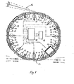
- FIG. 1 to which reference is made shows a device for bringing and keeping electrons in an orbitally accelerated path at regulated high speeds, up to very close to c, and for recording radiative interactions with other regions of space-time of these electrons at repeated free-flight intervals of their stepwise orbital path.
- the device is a modified electron accelerator of the synchrotron/electron storage ring type.
- an electron injector 10 at one (or multiple) sites from the interior (or exterior) of a mobile or stationary carrier or other framing of the instrument, into a toroidal vacuum tube 11, the vacuum of which can be produced by a vacuum pump mechanism (not illustrated).
- the electrons are linearly accelerated to and maintained at their desired speeds by a steerable energy supply in a radio-frequency resonant cavity 12 or other linear accelerator component of the instrument.
- the power supply of these magnets whose number may vary, is coordinated with the electron speed, i.e. the strength applied to the linear accelerator component of the instrument.
- the orbital deflection magnets are combined with a focussing magnet (magnet lens or collimator) 14, which keeps the electrons in a narrow and coordinated beam-like trajectory.
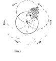
- the free-flight electron path and corresponding vacuum tube configuration are rectilinear. In all these intervals, except the sites of the electron injection and linear accelerator components, the electron motion is non-accelerated. In these repeated free-flight intervals, interaction recording components 15 are placed. It is proposed that radiative interactions in the visible and lower as well as higher radio-frequency wavelengths will be orientated along the same interaction cones relative to the electron direction in the free--flight intervals, as the synchrotron radiation when the electrons are orbitally accelerated under the deflecting magnets as shown at 16, where the direction and distribution of synchronous radiation from deflected high-speed electrons are indicated.
- any of the following existing recording components i.e. sufficiently sensitive interferometer, particle-counter, or electrostatic cathode-ray oscilloscope/oscillograph or their combinations can be mounted into the instrument. They can trace and indicate very small changes and can be facing the interior aspect of the rectilinear free-flight segments.
- the electron current pattern can be measured both in absolute terms and relative to the recordings in the other free-flight intervals of the ring.
- the electron-photon interactions can be of two kinds, absorption and emission.
- photon absorption in the free-flight electron intervals represent an interaction with a past region of space-time and is expressed and can be measured if it occurs in sufficiently many of the electrons as a corresponding desceleration of their current under the electric field recorder.
- An emission process in the interaction cone direction represents a communication with a future region and is expressed and measured as an acceleration.
- the order of the descelera- tion/acceleration which can be obtained from the recorder, corresponds to the intensity of the source, and the number of events to the size/density of this.
- the instrument may be of varying size. For most practical purposes a diameter of the electron orbital ring in the order of 15 - 100 meters or more will be suitable.
- the electrons circulate in a toroidal vacuum tube, which may be optically dense or transparent in vacuum centripetally open, perforated or openable, and in which the vacuum can be induced and maintained by a pump mechanism or (e.g. out in space) automatically (in which case the tube can be replaced by a centripetally open slit).
- the regularly spaced electromagnets provide forceful electromagnetical fields which accelerate the electrons into a stepwise orbital path. Between the deflecting magnets, the electron trajectory is non--accelerated and rectilinear.
- a particle accelerator of the synchrotron type modified and adjusted to the special requirements and properties of the present invention, provides a practicable mechanism for keeping electrons in synchronized motion with a wide range of steerable velocities, even approaching c, where direct electron--photon interactions with correspondingly slower virtual photons must emanate from other temporo-spatial regions of Universe and be directed along the interactions cones known and demonstrated in relation to the electron motion by the synchrotronous radiation.
- the velocity of the interacting photon in relation to the electron so that their speeds add to c can also be simply calculated. This speed furthermore gives the temporal transition factor of the interaction.
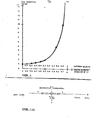
- the speed of the electron is 1/2 c
- the speed of the virtual photon is also 1/2 c
- the time transition factor must be 2; i.e. the virtual photons stem from a point two years ago in the terrestial reference in that space-time coordinate.
- the electron speed is 0.99 c
- the same factor will be 100 and the temporal transition 100 years; and if the electron speed is 0.999999 c
- the factor is 1,000,000 and the time displacement over the same distance 1,000,000 years.
- these examples show that the temporal transitions induced by changes in the electron speed are exponential.
- large velocity changes in the order of 0.2 - 0.1 c impose relatively unremarkable temporal displacements, but with higher electron velocities small differences in the speed induce gradually larger temporal shifts. This is illustrated by the graph of FIG. 3.
- the direction and time displacement factor of the virtual photon source can be simply computed.
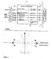
- the speed of the photon must be 0.01 c and it will be absorbed by the electron and emanate from a past region of space-time in relation to the observatory reference frame, left side of FIG. 4.
- the time displacement factor will be of exactly the same order but directed to the future instead of to the past.
- the interesting measurable present-time effect of the absorption/past and emission/future interactions, respectively, is that the former will be accompanied by a deceleration of the electrons interacted with, while the latter will be accompanied by an acceleration. By measuring the presence, magnitude,and numbers of such decelerations and/or accelerations, these interactions and their further important properties can be recorded.
- the magnitude of the deceleration/acceleration is proportionate to the intensity/wavelength of the photon source, while the number of interaction events, i.e. quantity of electrons affected by it in each pulse, . must be proportionate to its density/size.
- both direction, time displacement factor, past or future nature, intensity and size of the radiative object can easily be obtained from computation of measurable present-time characteristics of the mainstream electron pulses in the acceleration ring.
- it is suitable to utilize the free--flight intervals of the electron path between the deflecting magnets.
- a device is incorporated in the instrument, for detecting and recording the occurrence and nature of radiative interactions with the travelling electrons in these repeated intervals of their trajectory. This device is shown at 18 in FIG.
- FIG. 1 comprises a computer processing unit which is operatively connected to the accelerator 10 and the interaction recorders 15 as indicated in FIG. 1.
- the output of the computer is connected to a cathode-ray tube array or other observatorial display 19.
- the computer processing unit and the parameters processed therein are more clearly shown in FIG. 5.
- pulses of undisturbedly free-flying electrons passing through such a device would cause no deviations from the expected homogeneous pattern, but a sizeable number of decelerations and/or accelerations will induce corresponding perturbances in the electron current, which can be recorded as to type (deceleration or acceleration), intensity and quantity of events.
- Such particle or electrostatic field recorders can be spanned across most free-flight intervals of the electron storage ring between the deflecting magnets and thus cover segments over most of the accelerator circumference.
- the velocity and mainstream orientation of each electron pulse in the respective rectilinear free-flight intervals are known and adjustable, and hence the direction of the radiative source can easily be computed from these steerable and controllable factors.
- the information on past/future nature, intensity and quantitative magnitude of the source as derived from the electrostatical field detection component of the instrument can be directly transferred to and simply calculated by the same computer as diagrammatically shown in FIG. 5.
- exact data on direction, sign and size of time displacement factor, wavelength/intensity and magnitude of the interacting object (which over large space-time distances in most cases is a star or corresponding sizeable stellar matter) can be immediately calculated and processed by a computer component of the contrivance.
- the present invention constitutes a new and unique combination and assembly of practicable instrument components for the accomplishment and maintenance of adjustable and controllably rapid electron motions and for the earlier not realized functions of detecting, recording and computing decelerative or accelerative processes due to interactions with virtual photons from other regions of space-time of these electrons at repeated free-flying intervals of their path.
- this instrument henceforth provides the not previously described composite purposes and techniques of registration and detailed calculation of temporo-spatial electron-photon interaction shifts analogous to and by the same mechanism as a rotating black hole.
- the computer input and transactions of the data i.e.
- temporal displacement, intensity and size of the object are well suited for on-line computer processing and output to an optical or other display, e.g. as a visual image on a cathode-ray screen supplied with the necessary space-time coordinates and other useful reference and frame indicators.
- the assembled instrument can be accommodated for various purposes and vehicles, e.g. as a fixed earth-or satellite-bound temporo-spatial telescope station or around the outer circumference of a mobile space--craft, in which case a visual cathode-ray display system can be arranged continuously or interruptedly along the internal aspect of this electron accelerator ring or observatorial "horizon". This will then cover all spatial direction due to the steerable orientation in and around the vertical plane of the mobile carrier of the instrument (FIG. 6).
- a visual cathode-ray display system can be arranged continuously or interruptedly along the internal aspect of this electron accelerator ring or observatorial "horizon". This will then cover all spatial direction due to the steerable orientation in and around the vertical plane of the mobile carrier of the instrument (FIG. 6).
- the same principles and mechanisms can be utilized not only for receiving but also for transmitting and sending analogous impulses and signals to arbitrarily defined future or past regions of space-time, viz. by the controlled induction of rectilinear accelerations or decelerations of the electro pulses in the respective free-flight intervals of their trajectory.
Landscapes
- Physics & Mathematics (AREA)
- Spectroscopy & Molecular Physics (AREA)
- Engineering & Computer Science (AREA)
- General Engineering & Computer Science (AREA)
- High Energy & Nuclear Physics (AREA)
- Analysing Materials By The Use Of Radiation (AREA)
- Particle Accelerators (AREA)
- Measurement Of Radiation (AREA)
- Photometry And Measurement Of Optical Pulse Characteristics (AREA)
Priority Applications (1)
| Application Number | Priority Date | Filing Date | Title |
|---|---|---|---|
| AT86850001T ATE102384T1 (de) | 1985-01-02 | 1986-01-02 | Geraet fuer elektron-photonzusammenwirkungen. |
Applications Claiming Priority (2)
| Application Number | Priority Date | Filing Date | Title |
|---|---|---|---|
| US68841585A | 1985-01-02 | 1985-01-02 | |
| US688415 | 1985-01-02 |
Publications (3)
| Publication Number | Publication Date |
|---|---|
| EP0190108A2 true EP0190108A2 (de) | 1986-08-06 |
| EP0190108A3 EP0190108A3 (en) | 1988-10-19 |
| EP0190108B1 EP0190108B1 (de) | 1994-03-02 |
Family
ID=24764335
Family Applications (1)
| Application Number | Title | Priority Date | Filing Date |
|---|---|---|---|
| EP86850001A Expired - Lifetime EP0190108B1 (de) | 1985-01-02 | 1986-01-02 | Gerät für Elektron-Photonzusammenwirkungen |
Country Status (6)
| Country | Link |
|---|---|
| EP (1) | EP0190108B1 (de) |
| JP (1) | JPS61234000A (de) |
| AT (1) | ATE102384T1 (de) |
| AU (1) | AU597569B2 (de) |
| CA (1) | CA1233275A (de) |
| DE (1) | DE3689670T2 (de) |
Families Citing this family (1)
| Publication number | Priority date | Publication date | Assignee | Title |
|---|---|---|---|---|
| JPS63143900U (de) * | 1987-03-13 | 1988-09-21 |
Family Cites Families (2)
| Publication number | Priority date | Publication date | Assignee | Title |
|---|---|---|---|---|
| US3412337A (en) * | 1966-08-24 | 1968-11-19 | Atomic Energy Commission Usa | Beam spill control for a synchrotron |
| US4598415A (en) * | 1982-09-07 | 1986-07-01 | Imaging Sciences Associates Limited Partnership | Method and apparatus for producing X-rays |
-
1985
- 1985-12-24 CA CA000498610A patent/CA1233275A/en not_active Expired
- 1985-12-24 AU AU51773/85A patent/AU597569B2/en not_active Ceased
- 1985-12-27 JP JP60293331A patent/JPS61234000A/ja active Pending
-
1986
- 1986-01-02 DE DE3689670T patent/DE3689670T2/de not_active Expired - Fee Related
- 1986-01-02 AT AT86850001T patent/ATE102384T1/de not_active IP Right Cessation
- 1986-01-02 EP EP86850001A patent/EP0190108B1/de not_active Expired - Lifetime
Also Published As
| Publication number | Publication date |
|---|---|
| DE3689670D1 (de) | 1994-04-07 |
| AU597569B2 (en) | 1990-06-07 |
| AU5177385A (en) | 1986-07-10 |
| CA1233275A (en) | 1988-02-23 |
| ATE102384T1 (de) | 1994-03-15 |
| EP0190108A3 (en) | 1988-10-19 |
| JPS61234000A (ja) | 1986-10-18 |
| DE3689670T2 (de) | 1994-10-27 |
| EP0190108B1 (de) | 1994-03-02 |
Similar Documents
| Publication | Publication Date | Title |
|---|---|---|
| US5153665A (en) | Vaporizing particle velocimeter | |
| US20190178992A1 (en) | LIDAR Signal Acquisition | |
| US3060319A (en) | Optical synchronizer | |
| Torbert et al. | The electron drift instrument for MMS | |
| US3688584A (en) | Interferometric gravity gradiometer incorporating retroreflectors and means to correct for their relative shifting | |
| CN106842347B (zh) | 一种阵列式原子干涉重力梯度张量全分量的测量系统 | |
| SE432319B (sv) | Laserutrustad betraktningsanordning | |
| CN110221309A (zh) | 基于异步ToF离散点云的3D成像装置及电子设备 | |
| CN110658529A (zh) | 一种集成分束扫描单元及其制造方法 | |
| US20240230947A9 (en) | Preparation of cold atom clouds for measuring gravity gradient | |
| CN110471081A (zh) | 基于同步ToF离散点云的3D成像装置及电子设备 | |
| Krauz et al. | Laboratory modeling of the rotation of jets ejected from young stellar objects at studies the azimuthal structure of an axial jet at the PF-3 facility | |
| EP0190108B1 (de) | Gerät für Elektron-Photonzusammenwirkungen | |
| US4851688A (en) | Physical instrument for determining accelerations of electrons | |
| Bernhardt et al. | Heater‐induced cavities as optical tracers of plasma drifts | |
| JPH0356861A (ja) | 吊下げ粒子加速度計 | |
| EP4542794A1 (de) | Magnetische optische falle, physikalisches gehäuse für atomuhren, physikalisches gehäuse | |
| JPH01112165A (ja) | 移動光散乱体の速度測定装置 | |
| JP2857744B2 (ja) | 飛行体位置計測装置 | |
| US2767324A (en) | Apparatus for neutron detection | |
| Strom et al. | Giant radio galaxies | |
| US3090240A (en) | Electronic accelerometer | |
| Xie | Analysis Of Black Hole Merger from Gravitational Wave Generation and Observation | |
| US3452872A (en) | Shock-layer radiation measurement | |
| Boivin | Measurements of charged fusion product diffusion in TFTR |
Legal Events
| Date | Code | Title | Description |
|---|---|---|---|
| PUAI | Public reference made under article 153(3) epc to a published international application that has entered the european phase |
Free format text: ORIGINAL CODE: 0009012 |
|
| AK | Designated contracting states |
Kind code of ref document: A2 Designated state(s): AT BE CH DE FR GB IT LI LU NL SE |
|
| PUAL | Search report despatched |
Free format text: ORIGINAL CODE: 0009013 |
|
| AK | Designated contracting states |
Kind code of ref document: A3 Designated state(s): AT BE CH DE FR GB IT LI LU NL SE |
|
| 17P | Request for examination filed |
Effective date: 19890413 |
|
| 17Q | First examination report despatched |
Effective date: 19901217 |
|
| RAP3 | Party data changed (applicant data changed or rights of an application transferred) |
Owner name: TRELL, ERIK |
|
| GRAA | (expected) grant |
Free format text: ORIGINAL CODE: 0009210 |
|
| AK | Designated contracting states |
Kind code of ref document: B1 Designated state(s): AT BE CH DE FR GB IT LI LU NL SE |
|
| PG25 | Lapsed in a contracting state [announced via postgrant information from national office to epo] |
Ref country code: CH Effective date: 19940302 Ref country code: BE Effective date: 19940302 Ref country code: IT Free format text: LAPSE BECAUSE OF FAILURE TO SUBMIT A TRANSLATION OF THE DESCRIPTION OR TO PAY THE FEE WITHIN THE PRESCRIBED TIME-LIMIT;WARNING: LAPSES OF ITALIAN PATENTS WITH EFFECTIVE DATE BEFORE 2007 MAY HAVE OCCURRED AT ANY TIME BEFORE 2007. THE CORRECT EFFECTIVE DATE MAY BE DIFFERENT FROM THE ONE RECORDED. Effective date: 19940302 Ref country code: AT Effective date: 19940302 Ref country code: LI Effective date: 19940302 Ref country code: NL Effective date: 19940302 |
|
| REF | Corresponds to: |
Ref document number: 102384 Country of ref document: AT Date of ref document: 19940315 Kind code of ref document: T |
|
| REF | Corresponds to: |
Ref document number: 3689670 Country of ref document: DE Date of ref document: 19940407 |
|
| REG | Reference to a national code |
Ref country code: CH Ref legal event code: PL |
|
| ET | Fr: translation filed | ||
| NLV1 | Nl: lapsed or annulled due to failure to fulfill the requirements of art. 29p and 29m of the patents act | ||
| PLBE | No opposition filed within time limit |
Free format text: ORIGINAL CODE: 0009261 |
|
| STAA | Information on the status of an ep patent application or granted ep patent |
Free format text: STATUS: NO OPPOSITION FILED WITHIN TIME LIMIT |
|
| EAL | Se: european patent in force in sweden |
Ref document number: 86850001.8 |
|
| PG25 | Lapsed in a contracting state [announced via postgrant information from national office to epo] |
Ref country code: LU Free format text: LAPSE BECAUSE OF NON-PAYMENT OF DUE FEES Effective date: 19950131 |
|
| 26N | No opposition filed | ||
| PGFP | Annual fee paid to national office [announced via postgrant information from national office to epo] |
Ref country code: DE Payment date: 20000526 Year of fee payment: 14 |
|
| PG25 | Lapsed in a contracting state [announced via postgrant information from national office to epo] |
Ref country code: DE Free format text: LAPSE BECAUSE OF NON-PAYMENT OF DUE FEES Effective date: 20010103 |
|
| REG | Reference to a national code |
Ref country code: GB Ref legal event code: IF02 |
|
| PGFP | Annual fee paid to national office [announced via postgrant information from national office to epo] |
Ref country code: FR Payment date: 20040622 Year of fee payment: 19 |
|
| PGFP | Annual fee paid to national office [announced via postgrant information from national office to epo] |
Ref country code: GB Payment date: 20050617 Year of fee payment: 20 |
|
| PGFP | Annual fee paid to national office [announced via postgrant information from national office to epo] |
Ref country code: SE Payment date: 20050719 Year of fee payment: 20 |
|
| PG25 | Lapsed in a contracting state [announced via postgrant information from national office to epo] |
Ref country code: FR Free format text: LAPSE BECAUSE OF NON-PAYMENT OF DUE FEES Effective date: 20050930 |
|
| REG | Reference to a national code |
Ref country code: FR Ref legal event code: ST |
|
| PG25 | Lapsed in a contracting state [announced via postgrant information from national office to epo] |
Ref country code: GB Free format text: LAPSE BECAUSE OF EXPIRATION OF PROTECTION Effective date: 20060101 |
|
| REG | Reference to a national code |
Ref country code: GB Ref legal event code: PE20 |
|
| EUG | Se: european patent has lapsed |