EP0190106B1 - Landwirtschaftlicher Trockner mit direkter Heizung - Google Patents
Landwirtschaftlicher Trockner mit direkter Heizung Download PDFInfo
- Publication number
- EP0190106B1 EP0190106B1 EP86830019A EP86830019A EP0190106B1 EP 0190106 B1 EP0190106 B1 EP 0190106B1 EP 86830019 A EP86830019 A EP 86830019A EP 86830019 A EP86830019 A EP 86830019A EP 0190106 B1 EP0190106 B1 EP 0190106B1
- Authority
- EP
- European Patent Office
- Prior art keywords
- air
- fan
- heating chamber
- drier
- burner
- Prior art date
- Legal status (The legal status is an assumption and is not a legal conclusion. Google has not performed a legal analysis and makes no representation as to the accuracy of the status listed.)
- Expired - Lifetime
Links
- 238000010304 firing Methods 0.000 title claims abstract description 12
- 238000010438 heat treatment Methods 0.000 claims abstract description 20
- 238000002485 combustion reaction Methods 0.000 claims abstract description 8
- 239000000446 fuel Substances 0.000 claims abstract description 7
- 239000007788 liquid Substances 0.000 claims abstract description 6
- 238000001035 drying Methods 0.000 claims description 8
- 230000009977 dual effect Effects 0.000 claims description 3
- 238000004891 communication Methods 0.000 abstract description 2
- 239000012530 fluid Substances 0.000 abstract description 2
- 239000003546 flue gas Substances 0.000 description 3
- 239000000203 mixture Substances 0.000 description 3
- 238000010276 construction Methods 0.000 description 2
- 230000006866 deterioration Effects 0.000 description 2
- 239000004464 cereal grain Substances 0.000 description 1
- 230000003247 decreasing effect Effects 0.000 description 1
- 239000000428 dust Substances 0.000 description 1
- 239000008187 granular material Substances 0.000 description 1
- 238000009434 installation Methods 0.000 description 1
- 238000004519 manufacturing process Methods 0.000 description 1
- 239000002184 metal Substances 0.000 description 1
- 238000011144 upstream manufacturing Methods 0.000 description 1
- 239000002699 waste material Substances 0.000 description 1
Images
Classifications
-
- F—MECHANICAL ENGINEERING; LIGHTING; HEATING; WEAPONS; BLASTING
- F26—DRYING
- F26B—DRYING SOLID MATERIALS OR OBJECTS BY REMOVING LIQUID THEREFROM
- F26B9/00—Machines or apparatus for drying solid materials or objects at rest or with only local agitation; Domestic airing cupboards
- F26B9/06—Machines or apparatus for drying solid materials or objects at rest or with only local agitation; Domestic airing cupboards in stationary drums or chambers
- F26B9/08—Machines or apparatus for drying solid materials or objects at rest or with only local agitation; Domestic airing cupboards in stationary drums or chambers including agitating devices, e.g. pneumatic recirculation arrangements
- F26B9/082—Machines or apparatus for drying solid materials or objects at rest or with only local agitation; Domestic airing cupboards in stationary drums or chambers including agitating devices, e.g. pneumatic recirculation arrangements mechanically agitating or recirculating the material being dried
- F26B9/085—Machines or apparatus for drying solid materials or objects at rest or with only local agitation; Domestic airing cupboards in stationary drums or chambers including agitating devices, e.g. pneumatic recirculation arrangements mechanically agitating or recirculating the material being dried moving the material in a substantially vertical sense using conveyors or agitators, e.g. screws or augers with vertical axis, which are positioned inside the drying enclosure
-
- F—MECHANICAL ENGINEERING; LIGHTING; HEATING; WEAPONS; BLASTING
- F26—DRYING
- F26B—DRYING SOLID MATERIALS OR OBJECTS BY REMOVING LIQUID THEREFROM
- F26B19/00—Machines or apparatus for drying solid materials or objects not covered by groups F26B9/00 - F26B17/00
- F26B19/005—Self-contained mobile devices, e.g. for agricultural produce
-
- F—MECHANICAL ENGINEERING; LIGHTING; HEATING; WEAPONS; BLASTING
- F26—DRYING
- F26B—DRYING SOLID MATERIALS OR OBJECTS BY REMOVING LIQUID THEREFROM
- F26B23/00—Heating arrangements
- F26B23/02—Heating arrangements using combustion heating
-
- F—MECHANICAL ENGINEERING; LIGHTING; HEATING; WEAPONS; BLASTING
- F26—DRYING
- F26B—DRYING SOLID MATERIALS OR OBJECTS BY REMOVING LIQUID THEREFROM
- F26B9/00—Machines or apparatus for drying solid materials or objects at rest or with only local agitation; Domestic airing cupboards
- F26B9/10—Machines or apparatus for drying solid materials or objects at rest or with only local agitation; Domestic airing cupboards in the open air; in pans or tables in rooms; Drying stacks of loose material on floors which may be covered, e.g. by a roof
- F26B9/103—Machines or apparatus for drying solid materials or objects at rest or with only local agitation; Domestic airing cupboards in the open air; in pans or tables in rooms; Drying stacks of loose material on floors which may be covered, e.g. by a roof using fixed or removable drying air channels placed in the stack, e.g. horizontally or vertically
Definitions
- Subject of the present invention is a direct-firing agricultural drier of a type comprising a drying chamber adapted to accommodate products to be dried, means of dispensing air into said drying chamber, and a hot air generator having an air heating chamber with a feed conduit for the air to be heated and a conduit for delivering hot air to said dispensing means, a furnace in said heating chamber, a liquid fuel burner mounted externally of said heating chamber and connected to said furnace, and a fan for force feeding air into said dispensing means through said heating chamber, said fan having a delivery port connected to the feed conduit for the air to be heated.
- direct-firing refers, in an agricultural drier to that the related hot air generator is designed such that the hot flue gases enter the drying chamber admixed to the heated air; that is to say the furnace is open to the air heating chamber.
- the driers of the aforesaid type are widely employed in agriculture to reduce the relative moisture content of freshly harvested products in order to improve the preservability thereof.
- direct-firing agricultural drier are equipped with a hot air generator whose fan is located j downstream (with reference to the air flow direction through the heating chambe4 of the burner/ furnace assembly.
- the fans employed are mostly of the axial flow type.
- the feed air to the fan has a high thermal content. This involves a number of non-negligible problems both in the design and operation of the drier.
- That deteriorated performance of the fan reflects, in the majority of cases, in a decreased overall performance of the drier.
- a second problem resides in the high rate of wear of the fan impeller bearings due to their high operating temperature, of the impeller itself especially where this is of the centrifugal type, due to the occurrence of hot deformation, and of the motor members driving the fan.
- the problem underlying the present invention is that of providing a direct-firing agricultural drier which is operated on liquid fuel and so conceived, construction-and function-wise, as to overcome all the problems encountered with the cited prior art.
- the solutive idea to the above problem is that of mounting the hot air generator upstream of the air heating chamber and of so pressurizing the burner as to enable its installation externally of said heating"chamber.
- a direct-firing agricultural drier as indicated, which is characterized in that said burner includes a fan for force feeding of combustion air into the furnace, said fan having a combustion air intake which is connected through a conduit with said delivery port.
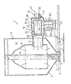
- Figure 1 Depicted in Figure 1 is a direct-firing agricultural drier of the wheel-mounted kind, comprehensively designated 1.
- the drier 1 comprises, on a dolly 2, a vertical axis cylindrical silo 3 having at the bottom a hopper 4 which tapers down into a well 5, an auger elevator 6 drawing from the well 5 and extending coaxially with the silo 3, a perforated drum 8 supported inside the silo 3 coaxially therewith, and a hot air generator 10 mounted in fluid communication with the drum 8.
- the silo 3 and drum 8 are constructed of perforated sheet metal, and defined in the space therebetween is a drying chamber 12 intended for accommodating a product to be dried, usually a granulate matter.
- the drum 8 has the function of dispensing hot air through the drying chamber 12 to thereby prompt removal of moisture from the product loaded therein.
- the hot air generator 10 comprises a centrifugal fan 15 of the dual intake type, i.e. having two intake ports indicated at 16a and 16b, respectively, and a delivery port 17.
- the fan 15 is supported on the dolly 2 and driven by motor means not shown, such as the power take-off of an agricultural tractor.
- the delivery port 17 is connected to a heating chamber 19 through a feed conduit 20 forthe air to be heated.
- a delivery conduit 21 extending between the chamber 19 and the drum 8 supplies hot air under pressure to the dispensing means.
- the furnace 22 has an end 24 open toward the conduit 21 and provided with a baffle plate 25.
- the hot air generator 10 further comprises a burner 27 mounted on the exterior of the chamber 19 and connected to the furnace 22 through a nosepiece 28.
- the burner 27 incorporates a fan 30forthe force feed of combustion air into the furnace 22 through the nosepiece 28 and is liquid fuel operated with fuel, such as oil, picked up from a tank not shown.
- the fan 30 has a combustion air intake 32 which is connected, through a bypass conduit 31 and the chamber 19, to the delivery port 17 of the fan 15.
- the drier 1 operates as follows: the productto be dried, such as cereal grains, is loaded into the chamber 12 and recirculated through said chamber upwardly through the conveyor 6.
- the hot air generator 10 is started. Air is drawn in for heating through the intakes 16a, 16b of the fan 15 and conveyed under pressure into the heating chamber 19.
- Some of the air compressed by the fan 15 is utilized to pressurize the burner 27 through the conduit 31, and the remainder is circulated in turbulent flow through the chamber 19 to remove heat from the furnace 22.
- This arrangement affords the possibility of keeping the outer shroud of the chamber 19 at near ambient temperature.
- the air forced in by the fan 15 and the hot flue gases issuing from the furnace 22 through the end 24 mix together and are dispensed into the drum 8 interior as a blend.
- the hot drying air that is, the mix of air being introduced by the fan and flue gases, is dispersed homogeneously through the produce being dried and flows out through the perforated walls of the silo 3.
- centrifugal fans even of the dual intake kind, which are known to be quieter and less expensive than axial flow fans, may be employed and are simple to install.
Landscapes
- Engineering & Computer Science (AREA)
- Mechanical Engineering (AREA)
- General Engineering & Computer Science (AREA)
- Life Sciences & Earth Sciences (AREA)
- Chemical & Material Sciences (AREA)
- Combustion & Propulsion (AREA)
- Sustainable Development (AREA)
- Agronomy & Crop Science (AREA)
- Drying Of Solid Materials (AREA)
- Compounds Of Unknown Constitution (AREA)
- Fertilizers (AREA)
Claims (2)
Priority Applications (1)
| Application Number | Priority Date | Filing Date | Title |
|---|---|---|---|
| AT86830019T ATE53252T1 (de) | 1985-01-25 | 1986-01-22 | Landwirtschaftlicher trockner mit direkter heizung. |
Applications Claiming Priority (2)
| Application Number | Priority Date | Filing Date | Title |
|---|---|---|---|
| IT19225/85A IT1183301B (it) | 1985-01-25 | 1985-01-25 | Essiccatoio agricolo a fuoco diretto |
| IT1922585 | 1985-01-25 |
Publications (3)
| Publication Number | Publication Date |
|---|---|
| EP0190106A2 EP0190106A2 (de) | 1986-08-06 |
| EP0190106A3 EP0190106A3 (en) | 1988-05-11 |
| EP0190106B1 true EP0190106B1 (de) | 1990-05-30 |
Family
ID=11155926
Family Applications (1)
| Application Number | Title | Priority Date | Filing Date |
|---|---|---|---|
| EP86830019A Expired - Lifetime EP0190106B1 (de) | 1985-01-25 | 1986-01-22 | Landwirtschaftlicher Trockner mit direkter Heizung |
Country Status (4)
| Country | Link |
|---|---|
| EP (1) | EP0190106B1 (de) |
| AT (1) | ATE53252T1 (de) |
| DE (1) | DE3671661D1 (de) |
| IT (1) | IT1183301B (de) |
Families Citing this family (4)
| Publication number | Priority date | Publication date | Assignee | Title |
|---|---|---|---|---|
| IT1186979B (it) * | 1985-09-19 | 1987-12-16 | Pedrotti Srl Flli | Essiccatoio per cereali con generatore d'aria calda a combustibile liquido |
| ITPD20010181A1 (it) * | 2001-07-18 | 2003-01-18 | Agrex Spa | Essiccatoio per cereali e materiali granulari in genere. |
| DE102010002134B4 (de) * | 2010-02-18 | 2015-10-29 | Christoph Kiener | Verfahren und Mittel zur Trocknung feuchter, biomassehaltiger Substanzen |
| IT201700053106A1 (it) * | 2017-05-16 | 2018-11-16 | Agrex Spa | Gruppo scambiatore di calore, gruppo generatore di calore e apparecchiatura per l´essicazione di prodotti sfusi |
Family Cites Families (2)
| Publication number | Priority date | Publication date | Assignee | Title |
|---|---|---|---|---|
| DE2037480C3 (de) * | 1970-07-29 | 1978-04-13 | Werner & Pfleiderer, 7000 Stuttgart | Vorrichtung zum Erzeugen eines Trocknungs-Luftstromes z.B. für Konvektionstrockner |
| US4402302A (en) * | 1981-06-19 | 1983-09-06 | Westelaken C | Air heating apparatus |
-
1985
- 1985-01-25 IT IT19225/85A patent/IT1183301B/it active
-
1986
- 1986-01-22 DE DE8686830019T patent/DE3671661D1/de not_active Expired - Fee Related
- 1986-01-22 EP EP86830019A patent/EP0190106B1/de not_active Expired - Lifetime
- 1986-01-22 AT AT86830019T patent/ATE53252T1/de not_active IP Right Cessation
Also Published As
| Publication number | Publication date |
|---|---|
| EP0190106A3 (en) | 1988-05-11 |
| EP0190106A2 (de) | 1986-08-06 |
| IT1183301B (it) | 1987-10-22 |
| DE3671661D1 (de) | 1990-07-05 |
| IT8519225A0 (it) | 1985-01-25 |
| ATE53252T1 (de) | 1990-06-15 |
Similar Documents
| Publication | Publication Date | Title |
|---|---|---|
| CN102016471A (zh) | 用于干燥物料的烘干机 | |
| US4142302A (en) | Multiple bin heat recycled grain drying | |
| CN101424482A (zh) | 干燥装置 | |
| CN108072260A (zh) | 一种室外型粮食烘干装置 | |
| EP0190106A2 (de) | Landwirtschaftlicher Trockner mit direkter Heizung | |
| US4523390A (en) | Peripheral exhaust system for high velocity dryer | |
| US2200379A (en) | Utilization of waste engine heat | |
| US4240209A (en) | Method of and apparatus for drying grain and the like | |
| US4526510A (en) | Double-walled centrifugal fan scroll and system of operation | |
| US2684668A (en) | Air heating furnace for drying purposes | |
| US4161294A (en) | Blower beater mill | |
| US4126410A (en) | Fuel burner | |
| JPH11294861A (ja) | 強制燃焼給湯器 | |
| US3386715A (en) | Air heating devices for crop dryers and the like | |
| US4869062A (en) | Burner for solid and other high ash fuels | |
| JPS62190380A (ja) | 穀粒乾燥機 | |
| US2564257A (en) | Forced air, fuel fired heater with scroll enclosed multiple annular heat transfer element | |
| JP2003247778A (ja) | 穀粒乾燥機の集穀室構造 | |
| US1700142A (en) | Manhole drier and ventilator | |
| US3606608A (en) | Encasement and fuel burner assembly | |
| CN217109530U (zh) | 一种生物颗粒燃烧机 | |
| US2999676A (en) | Grain conditioning apparatus | |
| US2418042A (en) | Spreader stoker apparatus | |
| JP4325091B2 (ja) | 遠赤外線穀粒乾燥機 | |
| US20260078927A1 (en) | Heating Appliance Including a Backward-Incline Blower |
Legal Events
| Date | Code | Title | Description |
|---|---|---|---|
| PUAI | Public reference made under article 153(3) epc to a published international application that has entered the european phase |
Free format text: ORIGINAL CODE: 0009012 |
|
| AK | Designated contracting states |
Kind code of ref document: A2 Designated state(s): AT BE CH DE FR GB LI LU NL SE |
|
| PUAL | Search report despatched |
Free format text: ORIGINAL CODE: 0009013 |
|
| AK | Designated contracting states |
Kind code of ref document: A3 Designated state(s): AT BE CH DE FR GB LI LU NL SE |
|
| 17P | Request for examination filed |
Effective date: 19880429 |
|
| 17Q | First examination report despatched |
Effective date: 19890126 |
|
| EL | Fr: translation of claims filed | ||
| RAP1 | Party data changed (applicant data changed or rights of an application transferred) |
Owner name: ARMAFOR S.R.L. |
|
| GRAA | (expected) grant |
Free format text: ORIGINAL CODE: 0009210 |
|
| AK | Designated contracting states |
Kind code of ref document: B1 Designated state(s): AT BE CH DE FR GB LI LU NL SE |
|
| PG25 | Lapsed in a contracting state [announced via postgrant information from national office to epo] |
Ref country code: SE Effective date: 19900530 Ref country code: NL Effective date: 19900530 Ref country code: LI Effective date: 19900530 Ref country code: CH Effective date: 19900530 Ref country code: BE Effective date: 19900530 Ref country code: AT Effective date: 19900530 |
|
| REF | Corresponds to: |
Ref document number: 53252 Country of ref document: AT Date of ref document: 19900615 Kind code of ref document: T |
|
| REF | Corresponds to: |
Ref document number: 3671661 Country of ref document: DE Date of ref document: 19900705 |
|
| ET | Fr: translation filed | ||
| REG | Reference to a national code |
Ref country code: CH Ref legal event code: PL |
|
| NLV1 | Nl: lapsed or annulled due to failure to fulfill the requirements of art. 29p and 29m of the patents act | ||
| PG25 | Lapsed in a contracting state [announced via postgrant information from national office to epo] |
Ref country code: LU Free format text: LAPSE BECAUSE OF NON-PAYMENT OF DUE FEES Effective date: 19910131 |
|
| PLBI | Opposition filed |
Free format text: ORIGINAL CODE: 0009260 |
|
| 26 | Opposition filed |
Opponent name: MECMAR S.R.L. Effective date: 19910225 |
|
| PG25 | Lapsed in a contracting state [announced via postgrant information from national office to epo] |
Ref country code: DE Effective date: 19911001 |
|
| PGFP | Annual fee paid to national office [announced via postgrant information from national office to epo] |
Ref country code: GB Payment date: 19911211 Year of fee payment: 7 |
|
| PLBN | Opposition rejected |
Free format text: ORIGINAL CODE: 0009273 |
|
| STAA | Information on the status of an ep patent application or granted ep patent |
Free format text: STATUS: OPPOSITION REJECTED |
|
| 27O | Opposition rejected |
Effective date: 19920224 |
|
| PG25 | Lapsed in a contracting state [announced via postgrant information from national office to epo] |
Ref country code: GB Effective date: 19930122 |
|
| GBPC | Gb: european patent ceased through non-payment of renewal fee |
Effective date: 19930122 |
|
| PGFP | Annual fee paid to national office [announced via postgrant information from national office to epo] |
Ref country code: FR Payment date: 19940131 Year of fee payment: 9 |
|
| PG25 | Lapsed in a contracting state [announced via postgrant information from national office to epo] |
Ref country code: FR Effective date: 19950929 |
|
| REG | Reference to a national code |
Ref country code: FR Ref legal event code: ST |