EP0189887B1 - Vorrichtung zur verzögerten Schliessung für Kontakte eines Strombegrenzungs-Lastschalters - Google Patents
Vorrichtung zur verzögerten Schliessung für Kontakte eines Strombegrenzungs-Lastschalters Download PDFInfo
- Publication number
- EP0189887B1 EP0189887B1 EP86101066A EP86101066A EP0189887B1 EP 0189887 B1 EP0189887 B1 EP 0189887B1 EP 86101066 A EP86101066 A EP 86101066A EP 86101066 A EP86101066 A EP 86101066A EP 0189887 B1 EP0189887 B1 EP 0189887B1
- Authority
- EP
- European Patent Office
- Prior art keywords
- contact arm
- contact
- ratchet
- pin
- arm
- Prior art date
- Legal status (The legal status is an assumption and is not a legal conclusion. Google has not performed a legal analysis and makes no representation as to the accuracy of the status listed.)
- Expired
Links
- 230000007246 mechanism Effects 0.000 claims abstract description 25
- 230000005520 electrodynamics Effects 0.000 claims description 9
- 238000000926 separation method Methods 0.000 description 4
- 230000008033 biological extinction Effects 0.000 description 2
- 241000607479 Yersinia pestis Species 0.000 description 1
- 230000006835 compression Effects 0.000 description 1
- 238000007906 compression Methods 0.000 description 1
- 230000002939 deleterious effect Effects 0.000 description 1
- 230000002045 lasting effect Effects 0.000 description 1
Images
Classifications
-
- H—ELECTRICITY
- H01—ELECTRIC ELEMENTS
- H01H—ELECTRIC SWITCHES; RELAYS; SELECTORS; EMERGENCY PROTECTIVE DEVICES
- H01H77/00—Protective overload circuit-breaking switches operated by excess current and requiring separate action for resetting
- H01H77/02—Protective overload circuit-breaking switches operated by excess current and requiring separate action for resetting in which the excess current itself provides the energy for opening the contacts, and having a separate reset mechanism
- H01H77/10—Protective overload circuit-breaking switches operated by excess current and requiring separate action for resetting in which the excess current itself provides the energy for opening the contacts, and having a separate reset mechanism with electrodynamic opening
- H01H77/102—Protective overload circuit-breaking switches operated by excess current and requiring separate action for resetting in which the excess current itself provides the energy for opening the contacts, and having a separate reset mechanism with electrodynamic opening characterised by special mounting of contact arm, allowing blow-off movement
- H01H77/104—Protective overload circuit-breaking switches operated by excess current and requiring separate action for resetting in which the excess current itself provides the energy for opening the contacts, and having a separate reset mechanism with electrodynamic opening characterised by special mounting of contact arm, allowing blow-off movement with a stable blow-off position
-
- H—ELECTRICITY
- H01—ELECTRIC ELEMENTS
- H01H—ELECTRIC SWITCHES; RELAYS; SELECTORS; EMERGENCY PROTECTIVE DEVICES
- H01H7/00—Devices for introducing a predetermined time delay between the initiation of the switching operation and the opening or closing of the contacts
-
- H—ELECTRICITY
- H01—ELECTRIC ELEMENTS
- H01H—ELECTRIC SWITCHES; RELAYS; SELECTORS; EMERGENCY PROTECTIVE DEVICES
- H01H75/00—Protective overload circuit-breaking switches in which excess current opens the contacts by automatic release of mechanical energy stored by previous operation of power reset mechanism
- H01H75/02—Details
- H01H75/04—Reset mechanisms for automatically reclosing a limited number of times
Definitions
- the invention relates to a device for preventing the transitory reclosing of the contacts of a current limiting circuit breaker after opening by a electrodynamic repulsion caused by a short circuit current before the current is extinguished. Interruption of short circuit currents can be due to two distinct causes: namely, a transitory rapid contact separation, or by the positive operation of the circuit breaker trip mechanism to hold the contacts open indefinitely.
- the two arms bearing the contacts are free to separate due to electrodynamic repulsion under intense short circuit currents. Opening of the contacts is subsequently completed by the circuit breaker operating mechanism,if the short circuit current is maintained for a time long enough to articulate the operating mechanism.
- the high separation speed of the contacts necessary to provide the current limitation can result in a rebound of the contacts upon separation resulting in a transitory reclosing of the contacts before the operating mechanism has had sufficient time to operate.
- the short circuit occurence is shorter than the response time of the operating mechanism, there is no need to open the contacts indefinitely. It is important however, to ensure continuity of circuit current in the absence of a real fault condition. With 3-phase loads protected by 3-pole breakers, it is essential to prevent a single-phase transitory short circuit occurrence from opening only one pole of the breaker, resulting in a dangerous condition known as "single phasing".
- the purpose of this invention is to delay reclosing of the circuit breaker contacts, after a short circuit interruption, for a period of time sufficient to allow the operating mechanism to open the contacts indefinitely providing that the short circuit lasts for a time longer than the reclosing delay.
- the invention consists essentially of a contact delay arrangement wherein a first contact arm bearing a first contact and a second contact arm bearing a second contact are both free to rotate around their respective pivot pins, the first pivot pin being connected to a contact arm support cam which is driven by the circuit breaker operating mechanism, the second pivot pin being housed in a contact arm support, the contacts being held closed by a pair of springs and being separated by means of electrodynamic repulsion upon the occurrence of a short circuit, said delay arrangement being characterized in that: it includes a spring loaded ratchet for locking the second contact arm by engaging a pawl pin attached to the second contact arm when the arm is driven by electrodynamic repulsion toward a stops to prevent the arm from returning to a closed position after striking against the step; a release lever releasing the ratchet through driving a bottom bumper of the release lever against a pin extending through the bottom of the spring loaded ratchet, thereby moving the ratchet out of engagement with the pawl pin and thereby allowing the second contact arm
- the ratchet is characterized by a pivot pin, around which it can rotate, by a detent engaging the corresponding pin of the second contact arm by said pin drivable by the bottom of said release lever and by a spring driving the detent of said ratchet causing it to engage the pawl pin of the second contact arm.
- the release lever is characterized by a pin pivotally supported by a pair of sockets formed in an insulating hood that surrounds both the contact arm support as well as part of the second arm; by the top bumper in the nature of a reinforced upper extension designed to receive both the post attached to the first contact arm, and the rear surface of the cam upon operation of the breaker operating mechanism and by the bottom bumper comprising a reinforced lower extension designed to contact the ratchet pin to release the ratchet, thereby unlocking the second contact arm.
- the ratchet locking the second contact arm and the release lever are formed by two members arranged one on each side of the second contact arm and spanning the width of the arm itself.
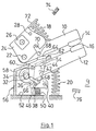
- the delay arrangement 9 is shown in the figures with a contact arm 10 and a contact arm 12 carrying contacts 14, 16 held in a closed position by springs 18 and 20 respectively.
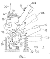
- the contact arm 10 rotates about a pin 22 supported by an operating cam 24 which, in turn rotates around an operating shaft 26 fitted with a post 28 to which a force represtend by an arrow 30 is applied when it is desired to cause cam 24 to rotate the shaft 26 for moving the contact arm 10 into the fully open position shown in fig. 3.
- the contact arm 12 rotates around a pin 32 captured within an elongated slot 34 formed in the contact am support 36. Also mounted on the contact arm support is a double ratchet 38, one on each side of the contact arm, only one of which is shown for purposes of clarity.
- the ratchet 38 rotates around a pin 40 through the contact arm support and has a detent 42 formed at the end opposite pin 40 which engages a post or pawl pin 44 attached to the contact arm 12.
- a pin 46 attached to the bottom of ratchet 38 is captured within radial slot 48 formed in the side of support 36 and is biased upwards within the slot by a compression spring 50 which is captured between the bottom of the ratchet 38 and the bottom circuit breaker support 52.
- a projection 54 is formed on each side of the contact arm support 36 for engaging the post 44 on contact arm 12 to stop movement of the arm against the bias exerted by spring 20.
- the whole contact arm support 36 is enclosed within an insulating hood 56 fitted with a cover 58.
- the cover 58 is provided with a hole on either side of the contact arm 12 to receive a pair of pins 60 formed on the exterior surface of a pair of release levers 62.
- One lever is arranged on each side of the contact arm and both levers are provided with top and bottom reinforced bumpers 64, 66.
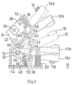
- the reinforced bumper 64 is engaged by a pest 68 extending from both sides of contact arm 10, as shown in fig. 2, or by the rear surface 78 of the cam 24, as shown in fig. 3.
- cam 24 has a notch 70 formed on a bottom surface for receiving the post 68, as indicated in phantom at 68a, during opening of the contact arm under repulsion due to short circuit current as indicated in phantom at 10a.
- An extension 72 on the top of cam 24 serves as a support for the spring 18 which is associated with contact arm 10.
- a pair of stops 74, 76 limit the travel of the contact arms 10 and 12, respectively.
- the contact arms 10, 12 move into the positions indicated in phantom as 10a and 12a, respectively.
- Spring 18 biases contact arm 10 in a clockwise direction whereas the spring 20 biases contact arm 12 in a counter-clockwise direction to hold the respective contacts in counter-balanced relation to each other.
- the cam 24 is rotated counter clockwise bringing its rear surface 78 against the top reinforced bumper 64 thereby driving the lever 62 clockwise and bringing the bottom reinforced bumper 66 against the pin 46 and releasing the post 44 from the detent 42.
- the contact arm 12 returns from the position 12b to the initial position shown in figs. 1 and 3 under the urgence of the spring 20.
- the contact arm 10 is carried by the action of the circuit breaker operating mechanism on cam 24 from the position indicated in phantom at 10b to the position against the stop 74 indicated in solid lines at 10 a which is the fully opened position of the contact 14.
Landscapes
- Physics & Mathematics (AREA)
- Electromagnetism (AREA)
- Keying Circuit Devices (AREA)
- Breakers (AREA)
- Emergency Protection Circuit Devices (AREA)
- Driving Mechanisms And Operating Circuits Of Arc-Extinguishing High-Tension Switches (AREA)
- Electronic Switches (AREA)
Claims (4)
- Kontaktverzögerungsanordnung für einen Strombegrenzungsschalter, wobei ein erster Kontaktarm (10), der ein erstes Kontaktstück (14) trägt, und ein zweiter Kontaktarm (12), der ein zweites Kontaktstück (16) trägt, beide frei sind für eine Drehung um ihre entsprechenden Drehstifte (22, 32), wobei der erste Drehstift (22) mit einer Kontaktarm-Halterungsnocke (24) verbunden ist, die durch den Schalterbetätigungsmechanismus angetrieben wird, der zweite Drehstift (32) in einer Kontaktarmhalterung (36) untergebracht ist, die Kontaktstücke (14, 16) durch zwei Federn (18, 20) geschlossen und durch elektrodynamische Abstoßung beim Auftreten eines Kurzschlusses getrennt werden, gekennzeichnet durch
eine federbelastete Sperrklinke (38) zum Verriegeln des zweiten Kontaktarmes (12) durch Eingriff mit einem an dem zweiten Kontaktarm (12) befestigten Klinkenstift (44), wenn der Arm durch elektrodynamische Abstoßung in Richtung auf einen Anschlag (76) bewegt wird, um zu verhindern, daß der Arm nach dem Aufprall gegen den Anschlag (76) in die Schließstellung zurückkehrt,
einen Freigabehebel (62), der die Sperrklinke (38) freigibt, indem ein unterer Dämpfer (66) des Freigabehebels (62) gegen einen Stift (46) bewegt wird, der sich durch die Unterseite der federbelasteten Sperrklinke (38) erstreckt, wodurch die Sperrklinke (38) sich aus einem Eingriff mit dem Klinkestift (44) bewegt und dadurch dem zweiten Kontaktarm (12) gestattet, in seine Schließstellung zurückzukehren, wobei der Freigabehebel (62) durch einen Zapfen (68), der an dem ersten Kontaktarm (10) befestigt ist, betätigt wird, wenn der erste Kontaktarm (10) in Richtung auf seine Schließstellung zurückkehrt, nachdem die Kontaktstücke getrennt worden sind, und der Freigabehebel (62) durch eine Oberfläche (78) der Halterungsnocke (24) betätigt wird, wenn die durch den Schalterbetätigungsmechanismus angetriebene Halterungsnocke den ersten Kontaktarm (10) in die Öffnungsstellung bewegt. - Kontaktverzögerungsanordnung nach Anspruch 1, dadurch gekennzeichnet, daß die Sperrklinke (38) einen Drehstift (40) aufweist, um den sie sich drehen kann, ein Zahn (42) an dem entsprechenden Klinkenstift (44) des zweiten Kontaktarms (12) angreift, der Stift (46) durch den unteren Dämpfer (66) des Freigabehebels (62) verschiebbar ist und eine Feder (50) den Zahn (42) der Sperrklinke (38) bewegt, damit dieser mit dem Klinkenstift (44) des zweiten Kontaktarms (12) in Eingriff kommt.
- Kontaktverzögerungsanordnung nach Anspruch 1, dadurch gekennzeichnet, daß der Freigabehebel (62) einen Stift (60) aufweist, der durch zwei Sockel schwenkbar gehaltert ist, die in einer Isolierhaube (56) ausgebildet sind, die sowohl die Kontaktarmhalterung (36) als auch einen Teil des zweiten Arms (12) umgibt, und daß der obere Dämpfer (64) eine verstärkte obere Verlängerung aufweist, die so ausgestaltet ist, daß sie sowohl den Zapfen (68), der an dem ersten Kontaktarm (10) befestigt ist, als auch die rückseitige Oberfläche (78) der Nocke (24) bei einer Betätigung des Schalterbetätigungsmechanismus aufnimmt, und daß der untere Dämpfer (66) eine verstärkte untere Verlängerung aufweist, die so gestaltet ist, daß sie den Sperrklinkenstift (46) kontaktiert, um die Sperrklinke (38) freizugeben, wodurch der zweite Kontaktarm (12) entriegelt wird.
- Kontaktverzögerungsanordnung nach Anspruch 1, dadurch gekennzeichnet, daß die Sperrklinke (38), die den zweiten Kontaktarm (12) verriegelt, und der Freigabehebel (62) durch zwei Teile gebildet sind, von denen jeweils einer auf jeder Seite des zweiten Kontaktarms (12) angeordnet sind und die die Breite des Arms (12) selbst überspannen.
Priority Applications (1)
| Application Number | Priority Date | Filing Date | Title |
|---|---|---|---|
| AT86101066T ATE71474T1 (de) | 1985-01-29 | 1986-01-27 | Vorrichtung zur verzoegerten schliessung fuer kontakte eines strombegrenzungs-lastschalters. |
Applications Claiming Priority (2)
| Application Number | Priority Date | Filing Date | Title |
|---|---|---|---|
| IT1927985 | 1985-01-29 | ||
| IT19279/85A IT1184864B (it) | 1985-01-29 | 1985-01-29 | Disposizione atta ad evitare e/o ritardare la richiusura di contatti in interruttori limitatori di corrente dopo un'apertura dei medesimi per repulsione |
Publications (3)
| Publication Number | Publication Date |
|---|---|
| EP0189887A2 EP0189887A2 (de) | 1986-08-06 |
| EP0189887A3 EP0189887A3 (en) | 1989-04-05 |
| EP0189887B1 true EP0189887B1 (de) | 1992-01-08 |
Family
ID=11156353
Family Applications (1)
| Application Number | Title | Priority Date | Filing Date |
|---|---|---|---|
| EP86101066A Expired EP0189887B1 (de) | 1985-01-29 | 1986-01-27 | Vorrichtung zur verzögerten Schliessung für Kontakte eines Strombegrenzungs-Lastschalters |
Country Status (4)
| Country | Link |
|---|---|
| EP (1) | EP0189887B1 (de) |
| AT (1) | ATE71474T1 (de) |
| DE (1) | DE3683301D1 (de) |
| IT (1) | IT1184864B (de) |
Cited By (1)
| Publication number | Priority date | Publication date | Assignee | Title |
|---|---|---|---|---|
| US6747532B1 (en) | 2002-12-23 | 2004-06-08 | General Electric Company | Method, system and apparatus for employing neutral poles in multipole circuit breakers |
Families Citing this family (2)
| Publication number | Priority date | Publication date | Assignee | Title |
|---|---|---|---|---|
| FR2792768B1 (fr) | 1999-04-22 | 2001-06-15 | Schneider Electric Ind Sa | Disjoncteur limiteur comportant un accumulateur d'energie auxiliaire |
| CN107958828B (zh) * | 2016-10-17 | 2020-03-31 | 浙江正泰电器股份有限公司 | 断路器 |
Family Cites Families (3)
| Publication number | Priority date | Publication date | Assignee | Title |
|---|---|---|---|---|
| US3469216A (en) * | 1966-07-12 | 1969-09-23 | Nikko Electric Mfg Co Ltd | High speed current limiting circuit breaker utilizing electromagnetic repulsion |
| NL142271B (nl) * | 1967-01-27 | 1974-05-15 | Terasaki Denki Sangyo Kk | Automatische schakelinrichting met beweegbare contactstangen openend onder invloed van elektrodynamische krachten. |
| US4144513A (en) * | 1977-08-18 | 1979-03-13 | Gould Inc. | Anti-rebound latch for current limiting switches |
-
1985
- 1985-01-29 IT IT19279/85A patent/IT1184864B/it active
-
1986
- 1986-01-27 AT AT86101066T patent/ATE71474T1/de not_active IP Right Cessation
- 1986-01-27 EP EP86101066A patent/EP0189887B1/de not_active Expired
- 1986-01-27 DE DE8686101066T patent/DE3683301D1/de not_active Expired - Lifetime
Cited By (1)
| Publication number | Priority date | Publication date | Assignee | Title |
|---|---|---|---|---|
| US6747532B1 (en) | 2002-12-23 | 2004-06-08 | General Electric Company | Method, system and apparatus for employing neutral poles in multipole circuit breakers |
Also Published As
| Publication number | Publication date |
|---|---|
| EP0189887A2 (de) | 1986-08-06 |
| IT8519279A0 (it) | 1985-01-29 |
| ATE71474T1 (de) | 1992-01-15 |
| EP0189887A3 (en) | 1989-04-05 |
| DE3683301D1 (de) | 1992-02-20 |
| IT1184864B (it) | 1987-10-28 |
Similar Documents
| Publication | Publication Date | Title |
|---|---|---|
| US4255732A (en) | Current limiting circuit breaker | |
| US4484046A (en) | Vacuum load break switch | |
| AU601169B2 (en) | Circuit breaker with shock resistant latch trip mechanism | |
| EP0218470B1 (de) | Ausschalter mit Klinke | |
| US4489295A (en) | Circuit interrupter with improved electro-mechanical undervoltage release mechanism | |
| US4286242A (en) | Mechanical interlock for low voltage circuit breakers | |
| JPH0338694B2 (de) | ||
| US3605052A (en) | Avoidance of switching device false off handle indication | |
| DK163616B (da) | Fejlstroems- og ledningsbeskyttelsesafbryder | |
| NZ242704A (en) | Circuit breaker with interlock preventing handle moving to off position when contacts welded closed | |
| JPH026181B2 (de) | ||
| US4635011A (en) | Circuit breaker with arm latch for high interrupting capacity | |
| JPH0119313Y2 (de) | ||
| JP4454823B2 (ja) | 回路遮断器用の制御機構 | |
| EP0189887B1 (de) | Vorrichtung zur verzögerten Schliessung für Kontakte eines Strombegrenzungs-Lastschalters | |
| US3940723A (en) | Instantaneously tripping device for circuit interrupter | |
| US3688237A (en) | Fused circuit breaker | |
| US3769477A (en) | Switch operating mechanism | |
| US5931289A (en) | Circuit breaker with quick closing mechanism | |
| US3849619A (en) | Circuit breaker with reverse override device | |
| US4295025A (en) | Circuit breaker with electromechanical trip means | |
| US4739291A (en) | Magnetic vacuum circuit breaker | |
| US4695690A (en) | Closing delay arrangement for current limiting circuit breaker contacts | |
| US5430422A (en) | Circuit breaker with anti-shock-off blocking mechanism | |
| CN215869224U (zh) | 一种断路器 |
Legal Events
| Date | Code | Title | Description |
|---|---|---|---|
| PUAI | Public reference made under article 153(3) epc to a published international application that has entered the european phase |
Free format text: ORIGINAL CODE: 0009012 |
|
| AK | Designated contracting states |
Kind code of ref document: A2 Designated state(s): AT BE CH DE FR GB LI NL SE |
|
| PUAL | Search report despatched |
Free format text: ORIGINAL CODE: 0009013 |
|
| AK | Designated contracting states |
Kind code of ref document: A3 Designated state(s): AT BE CH DE FR GB LI NL SE |
|
| 17P | Request for examination filed |
Effective date: 19890913 |
|
| 17Q | First examination report despatched |
Effective date: 19900925 |
|
| GRAA | (expected) grant |
Free format text: ORIGINAL CODE: 0009210 |
|
| AK | Designated contracting states |
Kind code of ref document: B1 Designated state(s): AT BE CH DE FR GB LI NL SE |
|
| REF | Corresponds to: |
Ref document number: 71474 Country of ref document: AT Date of ref document: 19920115 Kind code of ref document: T |
|
| PGFP | Annual fee paid to national office [announced via postgrant information from national office to epo] |
Ref country code: NL Payment date: 19920131 Year of fee payment: 7 |
|
| PGFP | Annual fee paid to national office [announced via postgrant information from national office to epo] |
Ref country code: SE Payment date: 19920210 Year of fee payment: 7 |
|
| PGFP | Annual fee paid to national office [announced via postgrant information from national office to epo] |
Ref country code: DE Payment date: 19920212 Year of fee payment: 7 |
|
| REF | Corresponds to: |
Ref document number: 3683301 Country of ref document: DE Date of ref document: 19920220 |
|
| PGFP | Annual fee paid to national office [announced via postgrant information from national office to epo] |
Ref country code: AT Payment date: 19920408 Year of fee payment: 7 |
|
| PGFP | Annual fee paid to national office [announced via postgrant information from national office to epo] |
Ref country code: GB Payment date: 19920416 Year of fee payment: 7 |
|
| PGFP | Annual fee paid to national office [announced via postgrant information from national office to epo] |
Ref country code: CH Payment date: 19920527 Year of fee payment: 7 |
|
| ET | Fr: translation filed | ||
| PLBE | No opposition filed within time limit |
Free format text: ORIGINAL CODE: 0009261 |
|
| STAA | Information on the status of an ep patent application or granted ep patent |
Free format text: STATUS: NO OPPOSITION FILED WITHIN TIME LIMIT |
|
| 26N | No opposition filed | ||
| PG25 | Lapsed in a contracting state [announced via postgrant information from national office to epo] |
Ref country code: GB Effective date: 19930127 Ref country code: AT Effective date: 19930127 |
|
| PG25 | Lapsed in a contracting state [announced via postgrant information from national office to epo] |
Ref country code: SE Effective date: 19930128 |
|
| PG25 | Lapsed in a contracting state [announced via postgrant information from national office to epo] |
Ref country code: LI Effective date: 19930131 Ref country code: CH Effective date: 19930131 |
|
| PG25 | Lapsed in a contracting state [announced via postgrant information from national office to epo] |
Ref country code: NL Effective date: 19930801 |
|
| NLV4 | Nl: lapsed or anulled due to non-payment of the annual fee | ||
| GBPC | Gb: european patent ceased through non-payment of renewal fee |
Effective date: 19930127 |
|
| REG | Reference to a national code |
Ref country code: CH Ref legal event code: PL |
|
| PG25 | Lapsed in a contracting state [announced via postgrant information from national office to epo] |
Ref country code: DE Effective date: 19931001 |
|
| EUG | Se: european patent has lapsed |
Ref document number: 86101066.8 Effective date: 19930810 |
|
| PGFP | Annual fee paid to national office [announced via postgrant information from national office to epo] |
Ref country code: FR Payment date: 20021212 Year of fee payment: 18 |
|
| PGFP | Annual fee paid to national office [announced via postgrant information from national office to epo] |
Ref country code: BE Payment date: 20021219 Year of fee payment: 18 |
|
| PG25 | Lapsed in a contracting state [announced via postgrant information from national office to epo] |
Ref country code: BE Free format text: LAPSE BECAUSE OF NON-PAYMENT OF DUE FEES Effective date: 20040131 |
|
| BERE | Be: lapsed |
Owner name: COMPAGNIA GENERALE ELETTROMECCANICA S.P.A. *CGE Effective date: 20040131 |
|
| PG25 | Lapsed in a contracting state [announced via postgrant information from national office to epo] |
Ref country code: FR Free format text: LAPSE BECAUSE OF NON-PAYMENT OF DUE FEES Effective date: 20040930 |
|
| REG | Reference to a national code |
Ref country code: FR Ref legal event code: ST |