EP0189339B1 - Liquid level height-measuring apparatus - Google Patents
Liquid level height-measuring apparatus Download PDFInfo
- Publication number
- EP0189339B1 EP0189339B1 EP19860400031 EP86400031A EP0189339B1 EP 0189339 B1 EP0189339 B1 EP 0189339B1 EP 19860400031 EP19860400031 EP 19860400031 EP 86400031 A EP86400031 A EP 86400031A EP 0189339 B1 EP0189339 B1 EP 0189339B1
- Authority
- EP
- European Patent Office
- Prior art keywords
- light
- optical
- distance
- measuring
- liquid level
- Prior art date
- Legal status (The legal status is an assumption and is not a legal conclusion. Google has not performed a legal analysis and makes no representation as to the accuracy of the status listed.)
- Expired
Links
Images


Classifications
-
- G—PHYSICS
- G01—MEASURING; TESTING
- G01F—MEASURING VOLUME, VOLUME FLOW, MASS FLOW OR LIQUID LEVEL; METERING BY VOLUME
- G01F23/00—Indicating or measuring liquid level or level of fluent solid material, e.g. indicating in terms of volume or indicating by means of an alarm
- G01F23/22—Indicating or measuring liquid level or level of fluent solid material, e.g. indicating in terms of volume or indicating by means of an alarm by measuring physical variables, other than linear dimensions, pressure or weight, dependent on the level to be measured, e.g. by difference of heat transfer of steam or water
- G01F23/28—Indicating or measuring liquid level or level of fluent solid material, e.g. indicating in terms of volume or indicating by means of an alarm by measuring physical variables, other than linear dimensions, pressure or weight, dependent on the level to be measured, e.g. by difference of heat transfer of steam or water by measuring the variations of parameters of electromagnetic or acoustic waves applied directly to the liquid or fluent solid material
- G01F23/284—Electromagnetic waves
- G01F23/292—Light, e.g. infrared or ultraviolet
Definitions
- the present invention relates to a light wave distance-meter for measuring a distance up to an object to be distance-measured by using light waves. More specifically, the invention relates to a liquid level height-measuring apparatus for measuring a height of a liquid level to be distance measured by using such a light wave distance-meter. This liquid level height-measuring apparatus is used for measuring a height of a level of crude oil in a crude oil tank.
- a lightwave distance-meter main body with an electric system is installed in a control housing far from the crude oil tank; an objective optical means is arranged in the crude oil tank for irradiating measuring light waves upon the level of the crude oil as a level to be distance-measured and condensing reflected measuring light waves reflected by the level of the crude oil; the object optical means and the light wave distance-meter main body are optically connected together by an optical fiber as a light wave transmission piping member; the distance-measuring light waves optically modulated at a given modulation frequency are generated from a distance-measuring light wave generating means of the light wave distance-meter main body; the distance-measuring light waves are led to the objective optical means through the optical fiber to irradiate the distance-measuring light waves upon the level surface of the crude oil; the reflected distance-measuring light waves reflected on the crude oil level surface are condensed by the objective optical means again; and the reflected distance-measuring light waves are
- the height of the liquid level is measured based on a phase difference as a time lag between the distance-measuring light waves and reflected distance-measuring light waves.
- the above liquid level height-measuring apparatus is adapted to directly measure the distance to be measured including the whole length of the light wave transmission piping member.
- the height of the liquid level is determined by subtracting the whole length of the light wave transmission piping member as a known physical amount from the measured distance.
- phase difference between the distance-measuring light waves and the reflected distance-measuring light waves both transmitted inside of the optical fiber is proportional to the whole lenngth of the whole length of the optical fiber
- the phase difference between the distance-measuring light waves and the reflected light waves increases with the increase in length of the optical fiber due to the above proportional relation to produce errors in the measured distance.
- the phase difference between the distance-measuring light waves and the reflected light waves changes due to bent portions on way of the arranged optical fiber and bending thereof by wind, and errors of the measured distance induced thereby increases with increase in length of the optical fiber.
- liquid level height measuring apparatuses are known by the documents WO-A-83/03135 and DE-A-2 630 789.
- the first document discloses in particular an apparatus as defined in the preamble of claim 1.
- the present invention has been made taking the above-mentioned circumstances into consideration, and is aimed at the provision of a liquid level height-measuring apparatus which can eliminate errors of measured distances due to increase in length of a light wave transmission piping member to the utmost.
- the liquid level height-measuring apparatus is characterized in that along the light wave transmission piping member is arranged a reference light wave transmission piping member which has substantially the same physical properties as those of the light wave transmission piping member, is set at substantially the same length as that of the light wave transmission piping member, and is adapted to circularly transmit the distance-measuring light waves as reference light waves toward a light receiving means thereby giving the distance-measuring light waves to the light receiving means.
- the whole length of the reference light wave transmission piping member is preliminary measured, and this measured data can be regarded as the whole length of the light wave transmission piping member.
- the height of the liquid level can be determined by substracting this measured datum from a distance-measured datum including the length of the light wave transmission piping member, while the error of the measured distance due to the length of the light wave transmission piping member being removed.
- the liquid level height-measuring apparatus is defined in the claim 1.
- the whole length of the reference light wave transmission piping means is preliminarily measured, and the height of the liquid level is determined by substracting thus measured data from a measured distance data while the whole length of the reference light wave transmission piping member being regarded as the light wave transmission piping means. Therefore, the present invention has the effect that distance-measuring errors with increase in the length of the light wave transmission piping member can be prevented from increasing so that the enhanced measuring accuracy of the liquid level height can be further expected.
- the invention also has effect that the structure thereof is simple.
- Other aspects of the described liquid level height measuring apparatus are claimed in the co-pending applications EP-A-188393 and 191658 with the same priority date.
- the liquid level height-measuring apparatus will be explained below with respect to a case of measuring a height of a level of crude oil in a crude oil tank thereby while referring to the attached drawings.
- M and T show a control housing and a crude oil tank, respectively.
- the control housing M is installed apart far from the crude oil tank T from the explosion-avoiding standpoint of view.
- a light wave distance-meter main body 1 with an electric system is installed in the control housing M, and an objective optical system unit 101 as an objective optical means is hanged from the ceiling of the crude oil tank T.
- the objective optical system unit 101 has function to irradiate distance-measuring light waves upon the level surface S of the crude oil as a liquid level to be distance-measured and condense the reflected distance-measuring light waves reflected on the liquid level surface S of the crude oil.
- the light wave distance-meter main body 1 and the objective optical system unit 101 are optically connected together through an opitcal fiber 102 as a light wave transmission piping member.
- the liquid level height-measuring apparatus 100 is substantially constituted by the light wave-distance-meter main body 1, the objective optical system unit 101 and the optical fiber 102.
- the objective optical system unit 101 has an objective lens 41 which is faced with the crude oil level surface S.
- the light wave distance-meter main body 1 is provided with a light wave distance-measuring circuit 2 for generating and receiving the distance-measuring light waves.
- the light wave distance-measuring circuit 2 has a distance-measuring light wave generating means for generating distance-measuring light waves optically modulated at a given modulation frequency and a light receiving means for receiving the reflected distance-measuring light waves led through the objective optical system unit 101.
- the optical fiber 102 consists of an outward optical fiber 104 optically connecting the distance-measuring light wave generating means to the objective optical system unit 101 and a return optical fiber 105 optically connecting the objective optical system unit 101 to the light receiving means.
- Reference numerals 104a and 105a indicate incident faces of the optical fibers 104 and 105, respectively, while reference numerals 104b and 105b do ejecting faces of the optical fibers 104 and 105, respectively.
- An incident face 104a of the outward optical fiber 104 faces a reflecting face 42a of a reflection prism 42, and an ejecting face 104b thereof faces a reflecting face 40a of a reflection prism 40.
- An incident face 105a of the return optical fiber 105 faces a reflecting face 40b of the reflection prism 40, and its ejecting face 105b faces a reflecting face 42b of the reflection prism 42.
- the distance-measuring light wave generating means is provided with a luminescent diode 205, which faces a reflecting face 41a of a reflection prism 41 through a shutter member 206.
- the light receiving means has a light receiving diode 30, which faces a reflecting face 41b of the reflection prism 41.
- the distance-measuring light waves optically modulated at a given modulation frequency are led to the reflection prism 41 and reflected on the reflecting face 41a thereof, and then the reflected light waves are led to the incident face 104a of the outward optical fiber 104 through the lenses 43 and 44.
- the distance-measuring light waves are transmitted inside of the outward optical fiber 104 and ejected from the ejecting face 104b thereof. Then, the light waves are led to the objective lens 41 where they are converted into a beam of parallel light rays, and the light rays are irradiated upon the crude oil level surface S.
- the distance-measuring light waves Upon being reflected on the crude oil level S, the distance-measuring light waves are converted into the reflected distance-measuring light waves.
- the reflected distance-measuring light waves are condensed by the objective lens 41 again and reflected by the reflecting face 40b of the reflection prism 40.
- the reflected distance-measuring light waves are transmitted inside of the return optical fiber 105 and ejected from the ejecting face 105b thereof, the ejected light waves being led to the light receiving element through the reflection prism 42, the lenses 44 and 43 and the reflection prism 41 to be photoelectrically converted.
- the reflection prisms 42 and the lens 44 constitutes a joint optical system 103.
- the light wave distance-measuring circuit 2 is adapted to generate a processing signal to an operation circuit 3 on the basis of the distance-measuring light waves and the reflected distance-measuring light waves.
- the operation circuit 3 is adapted to calculate a measurement distance L including the length I of the optical fiber 102 on the basis of the distance-measuring light waves and the reflected distance-measuring light waves.
- a reference light wave transmission piping member 5 is arranged between the light wave distance-meter main body 1 and the objective optical system unit 101.
- the reference light wave transmission piping member 5 is disposed along the optical fiber 102, and has substantially the same physical properties as those of the optical fiber 102.
- the length I' of the reference light wave transmission piping member 5 is designed to be almost the same as the length I of the optical fiber 102.
- An optical fiber is used as the reference light wave transmission piping member 5, and is provided with an incident face 5a and an ejecting face 5b.
- the incident face 5a is opposed to the luminescent diode 205, and the ejecting face 5b is opposed to the light receiving element 30.
- the reference light wave transmission piping member 5 receives the distance-measuring light waves generated from the luminescent diode 205 as reference light waves
- the reference linht wavce are circularly transmitted inside of the reference light wave transmission piping member 5, ejected toward the light receiving diode 30 from ejecting face 5b thereof and received by the light receiving diode 30.
- the operation circuit 3 preliminarily measures the whole length I' of the reference light wave transmission piping member 5, and the height H of the liquid level is determined by substracting the whole length I from the measured distance L while the whole length I' being regarded as the whole length I of the optical fiber 102.
- a calculating formula therefore is shown in the following: wherein V is a distance from the tip end of the objective lens-optical system unit 101 to the bottom B of the crude oil tank, and the distance L is the known physical amount.
- the height H of the liquid level is indicated as a measured datum by a display 4.
- the reference light wave transmission piping member 5 is formed completely independent of the outward optical fiber 104 and the return optical fiber 105 for measuring the distance.
- the present invention is not restricted thereto.
- the outward optical fiber and/or the return optical fiber may be also used for the reference light wave transmission when a light branching means and a light switch are used.
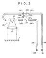
- Fig. 3 shows an embodiment of such a modification in which an outward optical fiber 104 is divided into 104'a and 104'b in the vicinity of an objective optical system unit 101, and a half mirror 201 as a light branching means is interposed therebetween.
- a return optical fiber 105 is divided into 105'a and 105'b in the vicinity of the objective optical system unit 101, and a half mirror 202 is interposed therebetween.
- a reflection light path 201 a of the half mirror 201 is coincident with an incident light path 202a of the other half mirror 202.
- a chopper 203 is so disposed as to be alternatively inserted between the half mirror 202 and the ejecting face of the return optical fiber 105'a and between the half mirror 201 and the half mirror 202 so that the light receiving element 30 may receive the distance-measuring light waves or the reference light waves selectively. Switching of the chopper 203 is performed by a rotary solenoid 204.
- Rv the nhnva construction the outward and return optical fibers 104 and 105 for measuring the distance may be also used for the reference light waves.
Landscapes
- Physics & Mathematics (AREA)
- Electromagnetism (AREA)
- Thermal Sciences (AREA)
- Fluid Mechanics (AREA)
- General Physics & Mathematics (AREA)
- Optical Radar Systems And Details Thereof (AREA)
- Length Measuring Devices By Optical Means (AREA)
- Measurement Of Optical Distance (AREA)
- Measurement Of Levels Of Liquids Or Fluent Solid Materials (AREA)
Applications Claiming Priority (2)
| Application Number | Priority Date | Filing Date | Title |
|---|---|---|---|
| JP132285U JPS61118032U (enExample) | 1985-01-09 | 1985-01-09 | |
| JP1322/85U | 1985-01-09 |
Publications (2)
| Publication Number | Publication Date |
|---|---|
| EP0189339A1 EP0189339A1 (en) | 1986-07-30 |
| EP0189339B1 true EP0189339B1 (en) | 1990-06-13 |
Family
ID=11498255
Family Applications (1)
| Application Number | Title | Priority Date | Filing Date |
|---|---|---|---|
| EP19860400031 Expired EP0189339B1 (en) | 1985-01-09 | 1986-01-08 | Liquid level height-measuring apparatus |
Country Status (3)
| Country | Link |
|---|---|
| EP (1) | EP0189339B1 (enExample) |
| JP (1) | JPS61118032U (enExample) |
| DE (1) | DE3671959D1 (enExample) |
Families Citing this family (2)
| Publication number | Priority date | Publication date | Assignee | Title |
|---|---|---|---|---|
| JPS63169521A (ja) * | 1987-01-07 | 1988-07-13 | Toshiba Corp | 変位計 |
| JPS6444819A (en) * | 1987-08-13 | 1989-02-17 | Nitto Machinery | Level gage utilizing laser light |
Family Cites Families (4)
| Publication number | Priority date | Publication date | Assignee | Title |
|---|---|---|---|---|
| DE2630789A1 (de) * | 1976-07-08 | 1978-01-12 | Ito Patent Ag | Verfahren zur messung des fuellstandes in behaeltern und anordnung zur durchfuehrung des verfahrens |
| EP0102390B1 (en) * | 1982-03-04 | 1987-06-16 | Kent Scientific and Industrial Projects Limited | Fluid level sensing apparatus |
| GB8305531D0 (en) * | 1983-02-28 | 1983-03-30 | Shell Int Research | Optical tank gauging |
| JPS6031072A (ja) * | 1983-07-30 | 1985-02-16 | Tokyo Optical Co Ltd | 光波距離計用光学アダプタ |
-
1985
- 1985-01-09 JP JP132285U patent/JPS61118032U/ja active Pending
-
1986
- 1986-01-08 DE DE8686400031T patent/DE3671959D1/de not_active Expired - Lifetime
- 1986-01-08 EP EP19860400031 patent/EP0189339B1/en not_active Expired
Also Published As
| Publication number | Publication date |
|---|---|
| JPS61118032U (enExample) | 1986-07-25 |
| EP0189339A1 (en) | 1986-07-30 |
| DE3671959D1 (de) | 1990-07-19 |
Similar Documents
| Publication | Publication Date | Title |
|---|---|---|
| US4692023A (en) | Optical adapter for a light-wave rangefinder | |
| US6975388B2 (en) | Optical-fiber refractometer | |
| US4745293A (en) | Method and apparatus for optically measuring fluid levels | |
| US4994682A (en) | Fiber optic continuous liquid level sensor | |
| US20040021100A1 (en) | Fiber-optic sensor for measuring level of fluid | |
| US4822135A (en) | Optical wave guide band edge sensor and method | |
| EP0196168B1 (en) | Fiber optic doppler anemometer | |
| EP0188393B1 (en) | Liquid level height-measuring apparatus | |
| US7463339B2 (en) | Device for measuring the distance to far-off objects and close objects | |
| EP0189339B1 (en) | Liquid level height-measuring apparatus | |
| US6005242A (en) | Environmental media and pressure sensor | |
| EP0274091B1 (en) | Optical displacement sensor | |
| RU2088883C1 (ru) | Лазерный прицел-дальномер | |
| EP0135423B1 (en) | Distance measuring system | |
| GB2076960A (en) | Liquid sensor | |
| EP0210341B1 (en) | Method and device for measuring coupling losses in single mode optical fibres | |
| GB2141223A (en) | Optical arrangements for monitoring refractive index of fluid | |
| JPH068724B2 (ja) | 光学的検出装置 | |
| EP0191658B1 (en) | Liquid level height-measuring apparatus | |
| GB2213018A (en) | Laser velocimeter | |
| RU2327959C2 (ru) | Волоконно-оптический сигнализатор уровня жидкости | |
| JPS5960699A (ja) | 光学センサ | |
| SU1458779A1 (ru) | Автоколлимационный способ определения показателя преломления клиновидных образцов | |
| CA2194483C (en) | Process and device for determining the refractive index of different mediums | |
| SU1679456A1 (ru) | Оптическа визирна система |
Legal Events
| Date | Code | Title | Description |
|---|---|---|---|
| PUAI | Public reference made under article 153(3) epc to a published international application that has entered the european phase |
Free format text: ORIGINAL CODE: 0009012 |
|
| 17P | Request for examination filed |
Effective date: 19860111 |
|
| AK | Designated contracting states |
Kind code of ref document: A1 Designated state(s): CH DE FR GB LI SE |
|
| 17Q | First examination report despatched |
Effective date: 19880830 |
|
| RAP1 | Party data changed (applicant data changed or rights of an application transferred) |
Owner name: KABUSHIKI KAISHA TOPCON |
|
| GRAA | (expected) grant |
Free format text: ORIGINAL CODE: 0009210 |
|
| AK | Designated contracting states |
Kind code of ref document: B1 Designated state(s): CH DE FR GB LI SE |
|
| REF | Corresponds to: |
Ref document number: 3671959 Country of ref document: DE Date of ref document: 19900719 |
|
| ET | Fr: translation filed | ||
| PLBE | No opposition filed within time limit |
Free format text: ORIGINAL CODE: 0009261 |
|
| STAA | Information on the status of an ep patent application or granted ep patent |
Free format text: STATUS: NO OPPOSITION FILED WITHIN TIME LIMIT |
|
| 26N | No opposition filed | ||
| PGFP | Annual fee paid to national office [announced via postgrant information from national office to epo] |
Ref country code: FR Payment date: 19911227 Year of fee payment: 7 |
|
| PGFP | Annual fee paid to national office [announced via postgrant information from national office to epo] |
Ref country code: GB Payment date: 19920103 Year of fee payment: 7 |
|
| PG25 | Lapsed in a contracting state [announced via postgrant information from national office to epo] |
Ref country code: GB Effective date: 19930108 |
|
| PGFP | Annual fee paid to national office [announced via postgrant information from national office to epo] |
Ref country code: CH Payment date: 19930119 Year of fee payment: 8 |
|
| GBPC | Gb: european patent ceased through non-payment of renewal fee |
Effective date: 19930108 |
|
| PG25 | Lapsed in a contracting state [announced via postgrant information from national office to epo] |
Ref country code: FR Effective date: 19930930 |
|
| REG | Reference to a national code |
Ref country code: FR Ref legal event code: ST |
|
| PG25 | Lapsed in a contracting state [announced via postgrant information from national office to epo] |
Ref country code: LI Effective date: 19940131 Ref country code: CH Effective date: 19940131 |
|
| REG | Reference to a national code |
Ref country code: CH Ref legal event code: PL |
|
| EAL | Se: european patent in force in sweden |
Ref document number: 86400031.0 |
|
| PGFP | Annual fee paid to national office [announced via postgrant information from national office to epo] |
Ref country code: SE Payment date: 19961216 Year of fee payment: 12 |
|
| PGFP | Annual fee paid to national office [announced via postgrant information from national office to epo] |
Ref country code: DE Payment date: 19970325 Year of fee payment: 12 |
|
| PG25 | Lapsed in a contracting state [announced via postgrant information from national office to epo] |
Ref country code: SE Free format text: LAPSE BECAUSE OF NON-PAYMENT OF DUE FEES Effective date: 19980109 |
|
| PG25 | Lapsed in a contracting state [announced via postgrant information from national office to epo] |
Ref country code: DE Free format text: LAPSE BECAUSE OF NON-PAYMENT OF DUE FEES Effective date: 19981001 |
|
| EUG | Se: european patent has lapsed |
Ref document number: 86400031.0 |