EP0189162A2 - Speiseeis-Schöpflöffel für die Abgabe von Speiseeiskugeln - Google Patents
Speiseeis-Schöpflöffel für die Abgabe von Speiseeiskugeln Download PDFInfo
- Publication number
- EP0189162A2 EP0189162A2 EP86100681A EP86100681A EP0189162A2 EP 0189162 A2 EP0189162 A2 EP 0189162A2 EP 86100681 A EP86100681 A EP 86100681A EP 86100681 A EP86100681 A EP 86100681A EP 0189162 A2 EP0189162 A2 EP 0189162A2
- Authority
- EP
- European Patent Office
- Prior art keywords
- piston
- cylinder
- scoop
- spoon
- scoop according
- Prior art date
- Legal status (The legal status is an assumption and is not a legal conclusion. Google has not performed a legal analysis and makes no representation as to the accuracy of the status listed.)
- Withdrawn
Links
Images

Classifications
-
- A—HUMAN NECESSITIES
- A47—FURNITURE; DOMESTIC ARTICLES OR APPLIANCES; COFFEE MILLS; SPICE MILLS; SUCTION CLEANERS IN GENERAL
- A47J—KITCHEN EQUIPMENT; COFFEE MILLS; SPICE MILLS; APPARATUS FOR MAKING BEVERAGES
- A47J43/00—Implements for preparing or holding food, not provided for in other groups of this subclass
- A47J43/28—Other culinary hand implements, e.g. spatulas, pincers, forks or like food holders, ladles, skimming ladles, cooking spoons; Spoon-holders attached to cooking pots
- A47J43/282—Spoons for serving ice-cream
Definitions
- This invention relates to a scoop for dispensing balls of ice cream.
- Traditional scoops for dispensing icecream balls comprise a hemispherical spoon, a respective sweeping band or doctor blade, and a pliers-like spring baised handle cooperating with a rack and pinion arrangement for actuating the sweeping band. Such traditional scoops tend to fatigue the operator when used for long time periods and are of very slow operation.
- Another object of this invention is to greatly increase, all the other conditions being equal, the number of the ice creams balls an operator can dispense in a time unit.
- Another object of this invention is to provide a scoop for dispensing balls of ice cream, which is of practical use, of reliable operation, and of relatively low manufacturing cost.
- a scoop for dispensing balls of ice cream comprising a spoon, a doctor blade or sweeping band pivotally mounted in the spoon, and a handle carrying the spoon with the sweeping band, characterized in that it has a motor housed inside the handle, a drive system for operatively connecting the motor to the sweeping band, and a control means for the motor, thereby each time the control means is actuated, the sweeping band effects a sequential rotary movement first in one direction and then in the opposite direction.
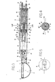
- a scoop 1 comprises an approximately hemispherical spoon or dish 2 in which an arcuate sweeping band or doctor blade 3 is pivotally mounted, through two side juts 4 and 5 so as to be able to turn about a diametrical axis X-X of the spoon (which also coincides with the longitudinal axis of the scoop).
- Three small pins, one of which is indicated at 5 and the other two (only one of which is visible in the drawings) are indicated at 6, project from the spoon 2.
- the pins 5 and 6 of the spoon are designed for bayonet coupling with and removal from one end of a holder 7 whose other end is shaped as a handgrip or handle 8.
- the pin 5 is integral with a secondary shaft 9, which can be rotated through a clutch 10, (see also Figure 5), by a primary drive shaft 11.
- the latter is driven by an electric motor 12 housed within the handgrip 8 along with reduction gearing 13.
- a pushbutton 14 On the exterior of the handgrip 8 and on its side confronting the spoon 2, there is provided a pushbutton 14 arranged to control an on/off switch (not shown) for the motor 12, whereas at the free end of the handgrip a cable 15 electrically connects the motor 12 to an electric power supply.
- the shaft 11 Upon energization of the electric motor 12, when depressing the pushbutton 14, the drive shaft 11 is rotated together with the doctor blade or sweeping band 3.
- the shaft 11 has two control marks generally indicated at 16 which are arranged at a predetermined angular distance from one another and designed to be "read” by a phototransistor or a photodiode 17 which is connected via suitable circuitry (not shown) to the power supply of the motor 12.
- the component 17 acts as a limit stop to reverse the direction of rotation of the motor 12 and that of the shaft 11 and the blade 3, once the shaft 9 has rotated through 180°, and to stop the motor once the shaft 9 and the blade 3 have reached their starting position. This operating cycle is repeated each time the pushbutton 14 is pressed.
- a scoop 20 according to the invention shown in Figure 2 is pneumatically operated. Some of its components which are identical with, or structurally similar to those of the scoop of Figure 1, are identified by the same reference numerals and further description thereof is deemed unnecessary.
- the drive shaft 11 is mounted for rotation on a bearing 21 through a seal 22 and extends to a chamber 23 formed in the holder 7.
- a piston 24 is slidably mounted which, on its end facing the shaft 11, has a blind hole 25 for slidably receiving therein the adjacent end of the shaft 11, whereas at its other end it carries seats 26.
- the piston 24 can slide on a section of the shaft 11.
- a small pin 27 laterally projecting from the shaft 11 slidably engages in a throughgoing helical guide or groove 28 formed in the piston wall.
- a straight groove 28' slidably engages with a fixed guide pin 29 fast with the holder 7, whereby the piston 24 can be displaced but cannot rotate in the chamber 23.
- the helical groove 28 while the piston is being displaced causes the shaft 11 to turn without being displaced.
- a buffer coil spring 30 having one end resting against the piston 24 and its other end against the bearing 21.
- a buffer spring 31 is also provided behind the piston 24 inside the handgrip 8.
- the pushbutton 14 is arranged to control a distributor which is generally indicated at 32 and housed within the handgrip 8.
- the distributor 32 is designed to shut off the flow of compressed air through two conduits, i.e. one conduit 33 for the forward stroke of the piston and the other 34 for its return stroke, the said conduits being connected to a source (not shown) of compressed air.
- a scoop 40 of Figures 3 and 4 could be regarded as a modification of the scoop 20 shown in Figure 2.
- the drive connection between the piston 24 and the shaft 11 comprises a groove 28 slidably engaged by a small pin 27 fast with the shaft 1 1.
- the piston 24 has a considerable extension on its end opposite that engaged by the shaft 11, and the chamber 23 spans the full length of the handle 8.
- the piston 24 has inside thereof three axial cavities arranged in succession, namely a cavity 25 for accomodating one end of the shaft 11, and intermediate cavity 41 adapted to slidably accomodate therein a valve element 42 configured as a slide valve distributor, and a hole 43 which has a smaller light than the cavity 41 and in which a small intemal rod 45 can sealingly slide to actuate the valve element 42.
- the piston 24 is also formed with two longitudinal bores 46 and 47 located at diametrically opposite positions with respect to the piston axis.
- two additional longitudinal bores 48 and 49 may be provided which act as thrust bores, as explained below.
- the chamber 23 is closed at the handle end by a stopper 50 which carries on its inner face two hollow guide pins 51 and 52 secured to it.
- the pins 51 and 52 are arranged and sized to slidably and sealingly fit in a respective longitudinal bore 46, 47 in the piston to act as guide elements for the piston.
- a supply duct 53 is connected to the stopper 50 and extends from a supply (not shown) of a compressed fluid - (air) and communicates with the hollow pin 51 and a return duct 54.
- a pushbutton 14 arranged to control a linkage including an outer longitudinal rod 56 pivoted to one end of a small lever 57 which can be fulcrumed on the line 53 and has its other end abutting against the end of the rod 45 projecting from the stopper 50.
- the valve element 42 has an axial cavity 58 in communication with two opposite cross bores 59 and 60 designed to be displaced in alignment with a respective passage, i.e. the bore 59 with a passage 61 for communication between the cavity 41 and the bore 46 in the piston and the bore 60 with a passage 62 for communication between the cavity 41 and the bore 47.
- the valve element 42 Upon pressing the pushbutton 14 rearwards, the valve element 42 is displaced until bore 60 is brought into alignment with the passage 62 to exhaust the pressurized air from the chamber 23 through the bore 47, the hollow pin 52 and the return line 54.
- air under pressure in the bore 46 and possibly in the thrust bores 48 and 49 in communication therewith moves the piston which slides along the shaft 1 1 and is caused to rotate until it abuts against the valve element 42 and is displaced by it back to its starting position (that shown in Figure 3).
- the pushbutton 14 and its respective control linkage is also set back to its home position ready for starting a new operating cycle.
- the spoon 2 can be attached to the holder 7 by means of a ring nut 63 arranged to be fitted on the end of the holder 7 and to be snap-locked at 64.
- the fluid-operated unit can comprise in general either a double- or single-acting cylinder/piston unit
- the scoop handle can have an angled set (e.g. by about 5 to 15°) with respect to the pivot axis of the sweeping band 3.
- the invention achieves all of the objects set forth in above, and in particular it can considerably alleviate the operator's effort while making it possible faster dispensing of ice cream balls.
- the bayonet coupling between the spoon and the holder allows rapid replacement of one spoon with one of different capacity for use on one and the same power-driven holder 7.
- the materials and dimensions may vary according to requirements.
Landscapes
- Engineering & Computer Science (AREA)
- Mechanical Engineering (AREA)
- Food Science & Technology (AREA)
- Confectionery (AREA)
Applications Claiming Priority (2)
| Application Number | Priority Date | Filing Date | Title |
|---|---|---|---|
| IT8490785 | 1985-01-24 | ||
| IT84907/85A IT1202003B (it) | 1985-01-24 | 1985-01-24 | Paletta per il prelievo e la formazione di palline di pasta gelato |
Publications (2)
| Publication Number | Publication Date |
|---|---|
| EP0189162A2 true EP0189162A2 (de) | 1986-07-30 |
| EP0189162A3 EP0189162A3 (de) | 1986-12-30 |
Family
ID=11325541
Family Applications (1)
| Application Number | Title | Priority Date | Filing Date |
|---|---|---|---|
| EP86100681A Withdrawn EP0189162A3 (de) | 1985-01-24 | 1986-01-20 | Speiseeis-Schöpflöffel für die Abgabe von Speiseeiskugeln |
Country Status (3)
| Country | Link |
|---|---|
| US (1) | US4758150A (de) |
| EP (1) | EP0189162A3 (de) |
| IT (1) | IT1202003B (de) |
Cited By (2)
| Publication number | Priority date | Publication date | Assignee | Title |
|---|---|---|---|---|
| DE9206062U1 (de) * | 1992-05-05 | 1992-08-06 | Fasolo, Gianni, 3575 Kirchhain | Motorisch betriebene Eiszange |
| WO1993002568A1 (de) * | 1991-08-10 | 1993-02-18 | Schuelling Christof | Portionierer für lebensmittel |
Families Citing this family (7)
| Publication number | Priority date | Publication date | Assignee | Title |
|---|---|---|---|---|
| US4850843A (en) * | 1988-08-09 | 1989-07-25 | Ralls W Fred | Ice cream server |
| US5326248A (en) * | 1993-01-21 | 1994-07-05 | The Vollrath Company, Inc. | Product serving apparatus |
| KR200283320Y1 (ko) * | 2002-04-18 | 2002-07-26 | (주)유한임페리얼 | 아이스크림 디셔 |
| USD487381S1 (en) | 2003-04-23 | 2004-03-09 | Hamilton Beach/Proctor-Silex, Inc. | Disher |
| CN104172953A (zh) * | 2014-08-19 | 2014-12-03 | 上海启济科技有限公司 | 一种量勺 |
| CN104489885A (zh) * | 2014-11-28 | 2015-04-08 | 陈青苹 | 一种丸子制作模具 |
| CN113017451B (zh) * | 2021-03-17 | 2024-01-23 | 丁扬阳 | 一种带有转动调料器的多功能漏勺 |
Family Cites Families (8)
| Publication number | Priority date | Publication date | Assignee | Title |
|---|---|---|---|---|
| US1763389A (en) * | 1924-08-04 | 1930-06-10 | Penrose E Chapman | Ice-cream spoon |
| US2412050A (en) * | 1945-01-29 | 1946-12-03 | Bert F Lawrence | Ice cream disher |
| US2547651A (en) * | 1947-12-17 | 1951-04-03 | Robert T Mccrum | Ice cream dipper |
| US2571729A (en) * | 1949-07-15 | 1951-10-16 | Bert F Lawrence | Ice-cream disher |
| US2631551A (en) * | 1951-05-04 | 1953-03-17 | Bert F Lawrence | Ice-cream scoop |
| US3598062A (en) * | 1969-06-06 | 1971-08-10 | Edward Weinstein | Food product scooper |
| US3784341A (en) * | 1972-04-06 | 1974-01-08 | T Magalotti | Hand tool for dispensing frozen food items |
| US3799407A (en) * | 1973-04-27 | 1974-03-26 | W Loethen | Semi-solid material dispensing including a power operated scoop |
-
1985
- 1985-01-24 IT IT84907/85A patent/IT1202003B/it active
-
1986
- 1986-01-13 US US06/818,417 patent/US4758150A/en not_active Expired - Fee Related
- 1986-01-20 EP EP86100681A patent/EP0189162A3/de not_active Withdrawn
Cited By (2)
| Publication number | Priority date | Publication date | Assignee | Title |
|---|---|---|---|---|
| WO1993002568A1 (de) * | 1991-08-10 | 1993-02-18 | Schuelling Christof | Portionierer für lebensmittel |
| DE9206062U1 (de) * | 1992-05-05 | 1992-08-06 | Fasolo, Gianni, 3575 Kirchhain | Motorisch betriebene Eiszange |
Also Published As
| Publication number | Publication date |
|---|---|
| US4758150A (en) | 1988-07-19 |
| EP0189162A3 (de) | 1986-12-30 |
| IT1202003B (it) | 1989-02-02 |
| IT8584907A0 (it) | 1985-01-24 |
Similar Documents
| Publication | Publication Date | Title |
|---|---|---|
| EP0189162A2 (de) | Speiseeis-Schöpflöffel für die Abgabe von Speiseeiskugeln | |
| US4625597A (en) | Screw driving apparatus | |
| US6601738B2 (en) | Lubricant dispenser | |
| US3254806A (en) | Power driven putty gun | |
| RU2432252C2 (ru) | Инструмент для демонтажа резца | |
| US6241130B1 (en) | Hand-held squeezing-out tool with a drive motor | |
| US3395704A (en) | Power operated syringe | |
| US5083619A (en) | Powered impact wrench | |
| EP3515358A1 (de) | Reinigungsvorrichtung | |
| CN101091082A (zh) | 油脂枪 | |
| US4353141A (en) | Power toothbrush | |
| US4486174A (en) | Arrangement for dispensing of maintenance media to medical, particularly dental, handpieces | |
| US5363726A (en) | Hand operated tool driver | |
| HU180242B (en) | Motor driven jackhammer | |
| US3334487A (en) | Impulse tool with improved cut-off device | |
| US2723580A (en) | Power driven wrench | |
| US5992695A (en) | Dispensing system | |
| GB2106024A (en) | Control for pneumatic tool eg a screwdriver | |
| JPS6158243B2 (de) | ||
| US4838364A (en) | Electrically powered screw tightening tool | |
| US4440324A (en) | Cartridge-type dispenser gun | |
| US1776659A (en) | Force-feed lubricator | |
| EP0555967A1 (de) | Drehmoment-Schraubenschlüssel | |
| US3401839A (en) | Liquid sampling and dispensing device | |
| US3099905A (en) | Portable tool |
Legal Events
| Date | Code | Title | Description |
|---|---|---|---|
| PUAI | Public reference made under article 153(3) epc to a published international application that has entered the european phase |
Free format text: ORIGINAL CODE: 0009012 |
|
| AK | Designated contracting states |
Kind code of ref document: A2 Designated state(s): AT BE DE FR GB LU NL |
|
| PUAL | Search report despatched |
Free format text: ORIGINAL CODE: 0009013 |
|
| AK | Designated contracting states |
Kind code of ref document: A3 Designated state(s): AT BE DE FR GB LU NL |
|
| 17P | Request for examination filed |
Effective date: 19870622 |
|
| 17Q | First examination report despatched |
Effective date: 19880614 |
|
| STAA | Information on the status of an ep patent application or granted ep patent |
Free format text: STATUS: THE APPLICATION IS DEEMED TO BE WITHDRAWN |
|
| 18D | Application deemed to be withdrawn |
Effective date: 19881025 |