EP0189151A2 - Apparatus for producing an electrophotographic print - Google Patents
Apparatus for producing an electrophotographic print Download PDFInfo
- Publication number
- EP0189151A2 EP0189151A2 EP86100615A EP86100615A EP0189151A2 EP 0189151 A2 EP0189151 A2 EP 0189151A2 EP 86100615 A EP86100615 A EP 86100615A EP 86100615 A EP86100615 A EP 86100615A EP 0189151 A2 EP0189151 A2 EP 0189151A2
- Authority
- EP
- European Patent Office
- Prior art keywords
- receptor
- holder
- developing unit
- groove
- absorbent material
- Prior art date
- Legal status (The legal status is an assumption and is not a legal conclusion. Google has not performed a legal analysis and makes no representation as to the accuracy of the status listed.)
- Granted
Links
Images
Classifications
-
- G—PHYSICS
- G03—PHOTOGRAPHY; CINEMATOGRAPHY; ANALOGOUS TECHNIQUES USING WAVES OTHER THAN OPTICAL WAVES; ELECTROGRAPHY; HOLOGRAPHY
- G03G—ELECTROGRAPHY; ELECTROPHOTOGRAPHY; MAGNETOGRAPHY
- G03G15/00—Apparatus for electrographic processes using a charge pattern
- G03G15/01—Apparatus for electrographic processes using a charge pattern for producing multicoloured copies
- G03G15/0105—Details of unit
- G03G15/0121—Details of unit for developing
-
- G—PHYSICS
- G03—PHOTOGRAPHY; CINEMATOGRAPHY; ANALOGOUS TECHNIQUES USING WAVES OTHER THAN OPTICAL WAVES; ELECTROGRAPHY; HOLOGRAPHY
- G03G—ELECTROGRAPHY; ELECTROPHOTOGRAPHY; MAGNETOGRAPHY
- G03G15/00—Apparatus for electrographic processes using a charge pattern
- G03G15/06—Apparatus for electrographic processes using a charge pattern for developing
- G03G15/10—Apparatus for electrographic processes using a charge pattern for developing using a liquid developer
- G03G15/11—Removing excess liquid developer, e.g. by heat
-
- G—PHYSICS
- G03—PHOTOGRAPHY; CINEMATOGRAPHY; ANALOGOUS TECHNIQUES USING WAVES OTHER THAN OPTICAL WAVES; ELECTROGRAPHY; HOLOGRAPHY
- G03G—ELECTROGRAPHY; ELECTROPHOTOGRAPHY; MAGNETOGRAPHY
- G03G21/00—Arrangements not provided for by groups G03G13/00 - G03G19/00, e.g. cleaning, elimination of residual charge
- G03G21/0088—Arrangements not provided for by groups G03G13/00 - G03G19/00, e.g. cleaning, elimination of residual charge removing liquid developer
Definitions
- the present invention relates generally to an apparatus for producing an electrophotographic print on a photosensitive material, and more particularly, a wet-type electrophotographic copying machine including a device for removing the used developer remaining on the photosensitive material.
- a wet-type electrophotographic copying machine hereinafter referred to merely as the copying machine
- the common practice is to use a pneumatic knife whereby the remainder of developer on the sensitive receptor is removed.
- the used developer blown by the pneumatic knife is likely to deposit at one spot on the receptor holder, and as the deposit becomes excessive, it tends to fall in droplets, and eventually returns to the reservoir.
- the problem is that the used developer has a reduced toner concentration. If such a diluted developer enters the reservoir, the concentration of toner in the developer therein is likely to decrease, thereby resulting in a deteriorated developing ability. This requires special care to be constantly taken so as to keep the toner concentration adequate.
- color toners it may happen that one color gets mixed with another, thereby spoiling the finished color tone. This will be fatal to the color copying.
- the present invention is directed to solve the problems pointed out above, and has for its object to provide a copying machine including a device for removing the used developer remaining on the sensitive receptor without returning it to the reservoir, thereby keeping the developer in the reservoir constantly fresh.
- an apparatus for producing an electrographic print on a photosensitive receptor placed on a holder so as to produce an electrostatic latent image on the receptor by projecting light thereon comprising a developing unit located below the receptor holder, the developing unit including a developing section, the developing unit or the receptor holder being movable in relation to the other, the developing section supplying a developer to the sensitive receptor so as to make the electrostatic latent image visible; and means for collecting the used developer from the sensitive receptor, the collecting means including a pneumatic knife for blowing the used developer on the sensitive receptor to a place of collection, and means for receiving the used developer brought by the pneumatic knife, the receiving means being provided on that surface of the receptor holder which is outside the sensitive receptor, the receiving means being provided in a direction transverse to the direction in which the receptor holder or the developing unit is moved.
- photosensitive receptor As the photosensitive receptor the following may be used in conjunction with the present invention:
- the illustrated example is a color proof .electrophotographic copying machine.
- the application of the present invention is not limited to it, but the color proof copying machine has been taken up for illustration purpose only.
- the machine is used, prior to the regular printing, to see whether the film obtained through color separation of the original is appropriate or not.
- the machine functions as a proofreader.
- the machine is operated as follows:
- an electrostatic charger 5 is caused to run in the direction of arrow (B), during which electrostatic charge is given on the entire surface of the photosensitive receptor 3.
- a color separation film (e.g. for cyan) 4 is overlaid on the charged receptor 3, whose position is also decided by means of pins and secured under suction.
- a light 6 is lit so that the image on the film 4 is projected onto the receptor 3, thereby producing the electrostatic latent image thereon.
- the color separation film 4 is removed out of the receptor 3, which is still secured under suction.
- the receptor holder 1 is moved in the direction of arrow (A) until the receptor 3 looks downward as shown in Figure 1.
- the developing section 7c in a wet-type developing unit 7 which corresponds to the color separation film 4 is raised in the direction of arrow (D), and simultaneously, the developing unit 7 is moved in the direction of arrow (D). In this way the latent image on the receptor 3 is subjected to color development, thereby producing visible color image.
- the unit includes a suction groove 11 whose depth is perpendicular to the direction of arrow (D) in which the developing unit 7 is moved, a suction duct 14 connected to the groove 11 through a pipe 12, the duct 14 being producted through a rotary shaft 13, and a suction means 17 connected to the suction duct 14, an inlet pipe 15 and a drain 16.
- a remainder 19 of the liquid developer is sucked from the surface of the receptor 3. The sucked remainder 19 is led to the drain 16 through the groove 11, pipe 12 and duct 14.
- the groove 11 is provided with an absorbent material 18, such as felt or sponge with a space lla at the bottom of the groove 11.
- the space lla is intended to enable the sucking force from the pipe 12 to diffuse extensively against the absorbent material 18. If no space lla is present, the sucking force is likely to concentrate on the part where the pipe 12 is jointed to the groove 18.
- the developing unit 7 includes developing sections 7C, 7M and 7Y for cyan, magenta and yellow, respectively. In these sections the respective color electrostatic latent images are developed. Where required, another section (not shown) is provided for black. On the sensitive receptor 3 a particular latent image for one color is produced, which is developed with the particular color toner. This procedure is repeated several times until all the color images are developed.
- Each section 7C, 7M and 7Y is moved reciprocally in the directions of arrow (D). This is achieved by mounting these sections on a carrier 20, which is movable in the direction of arrow (D). On the carrier 20 each section is also movable in the direction of arrow (C) independently of the others. More specifically the carrier 20 is moved by means of a driving mechanism including a motor, chains and the like (not shown) along a guide rail 21 to and fro in the direction of arrow (D).
- a lifting unit 25 including a motor 22, a crank 23, a lifter table 24 and the like is operated to raise the section 7C until it comes near the sensitive receptor 3.
- a developer 27 in a reservoir 26 is supplied to the surface 2 of the receptor 3 by means of a pump (not shown).
- the section 7C continues. to move until it covers the whole surface 2 of the receptor 3. When it has passed the receptor 3, the supply of developer is automatically stopped.
- Each section 7C, 7M and 7Y is equipped with a pneumatic knife 8 including an air outlet 8a, the pneumatic knife being located adjacent to electrodes 9.
- the pneumatic knife 8 is to blow the liquid remainder 19 on the receptor 3 in the direction of arrow (D) in which the section 7C, 7M or 7Y is moved.
- the groove 11 is engraved perpendicularly to the direction of (D) in which the developing section is moved, wherein the groove is provided with the absorbent material 18, having the small space lla left at the bottom.
- the invention is not limited to this structure.
- the absorbent material can be fully packed in the groove without the space lla, or alternatively it is possible to use no absorbent material at all although the efficiency is reduced.
- the cross-section of the groove 11 can be shaped as shown in Figure 3, that is, the opening is constricted whereas the passage is widened toward the depth.
- many pores can be arranged crosswisely of the width of the holder 2, wherein they are preferably spaced from one to another at minimum intervals.
- the absorbent material 18 felt, sponge, cloth or the like can be selectively used. However, it is important for the material not to extrude from the surface 2 of the receptor holder 1. To this end it is preferred to make a recess on the surface of the holder, so as to have the absorbent material packed therein.
- the absorbent material When the absorbent material is saturated with the used developer, it is required to dry it; for example, by ejecting hot air onto the wet absorbent material. Another possible way is to suck the absorbed developer by means of a suitable sucking device provided outside the recepter holder 1, wherein a sucking pat is intermittently applied to the saturated material.
- the absorbent material can be provided in such a manner as to cover the suction opening provided on the surface of the holder 1, and lead the developer out of the holder surface 2 through the holder body.
- the groove When a negligible amount of developer remains, the groove may be provided with no absorbent material. In this case there will be a danger of the developer dropping through the groove, but as it stays on the inside walls of the groove, it rarely happens that it falls in droplets.
- a pulse motor For driving the developing unit 7 in the direction of arrow (D) a pulse motor can be employed, whereby the top or rear end of the receptor 3 held on the holder 1 is detected as previously set, thereby effecting the automatic supply of developer.
- the present invention has the following advantages:
Abstract
Description
- The present invention relates generally to an apparatus for producing an electrophotographic print on a photosensitive material, and more particularly, a wet-type electrophotographic copying machine including a device for removing the used developer remaining on the photosensitive material.
- In a wet-type electrophotographic copying machine, hereinafter referred to merely as the copying machine, it is essential to remove the used developer remaining on the photosensitive material, hereinafter referred to as a sensitive receptor or merely a receptor. The common practice is to use a pneumatic knife whereby the remainder of developer on the sensitive receptor is removed.
- However, the used developer blown by the pneumatic knife is likely to deposit at one spot on the receptor holder, and as the deposit becomes excessive, it tends to fall in droplets, and eventually returns to the reservoir. The problem is that the used developer has a reduced toner concentration. If such a diluted developer enters the reservoir, the concentration of toner in the developer therein is likely to decrease, thereby resulting in a deteriorated developing ability. This requires special care to be constantly taken so as to keep the toner concentration adequate. When color toners are used, it may happen that one color gets mixed with another, thereby spoiling the finished color tone. This will be fatal to the color copying.
- The present invention is directed to solve the problems pointed out above, and has for its object to provide a copying machine including a device for removing the used developer remaining on the sensitive receptor without returning it to the reservoir, thereby keeping the developer in the reservoir constantly fresh.
- Other objects and advantages of the present invention will become apparent from the detailed description given hereinafter; it should be understood, however, that the detailed description and specific embodiment are given by way of illustration only, since various changes and modifications within the spirit and scope of the invention will become apparent to those skilled in the art from this detailed description.
- According to the present invention, there is provided an apparatus for producing an electrographic print on a photosensitive receptor placed on a holder so as to produce an electrostatic latent image on the receptor by projecting light thereon, the apparatus comprising a developing unit located below the receptor holder, the developing unit including a developing section, the developing unit or the receptor holder being movable in relation to the other, the developing section supplying a developer to the sensitive receptor so as to make the electrostatic latent image visible; and means for collecting the used developer from the sensitive receptor, the collecting means including a pneumatic knife for blowing the used developer on the sensitive receptor to a place of collection, and means for receiving the used developer brought by the pneumatic knife, the receiving means being provided on that surface of the receptor holder which is outside the sensitive receptor, the receiving means being provided in a direction transverse to the direction in which the receptor holder or the developing unit is moved.
- As the photosensitive receptor the following may be used in conjunction with the present invention:
- a backing of relatively electrically conductive material sheet such as paper or plastic film coated with an electroconductive material, or of metal plate having a coating of electrophotoconductive material layer such as titanium dioxide, zinc oxide, and the like, dispersed in a resinous binder on one surface thereof to provide the electrophotoconductive surface. It is especially advantageous to use a photosensitive receptor containing titanium dioxide, this results in a multicolor print image having high contrast with good continuous gradation of the image such as that pictorial tone resembling the appearance obtainable in silver halide photography.
-
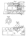
- Figure 1 is a cross-section through a wet-type electrophotographic copying machine including a device embodying the present invention;
- Figure 2 is a cross-sectional side view of the copying machine of Figure 1; and
- Figure 3 is a schematic view showing a modified version of the device embodying the present invention.
- The illustrated example is a color proof .electrophotographic copying machine. Of course the application of the present invention is not limited to it, but the color proof copying machine has been taken up for illustration purpose only. The machine is used, prior to the regular printing, to see whether the film obtained through color separation of the original is appropriate or not. The machine functions as a proofreader.
- The machine is operated as follows:
- In Figure 2 a holder 1 for holding a photosensitive receptor 3 rotatively supported on a frame (not shown) is rotated in the direction of arrow (A), so as to enable its
holder surface 2 to turn upward on which the photosensitive receptor 3 is placed. The position of the receptor 3 is decided by the use of pins (not shown), and secured thereon under suction. - Then, an electrostatic charger 5 is caused to run in the direction of arrow (B), during which electrostatic charge is given on the entire surface of the photosensitive receptor 3. Subsequently, a color separation film (e.g. for cyan) 4 is overlaid on the charged receptor 3, whose position is also decided by means of pins and secured under suction. Finally a light 6 is lit so that the image on the film 4 is projected onto the receptor 3, thereby producing the electrostatic latent image thereon.
- The color separation film 4 is removed out of the receptor 3, which is still secured under suction. At this stage the receptor holder 1 is moved in the direction of arrow (A) until the receptor 3 looks downward as shown in Figure 1. The developing section 7c in a wet-
type developing unit 7 which corresponds to the color separation film 4 is raised in the direction of arrow (D), and simultaneously, the developingunit 7 is moved in the direction of arrow (D). In this way the latent image on the receptor 3 is subjected to color development, thereby producing visible color image. - In this way exposure and development are repeated for the whole surface of one receptor 3 until the image on the color original is completely reproduced as a proof.
- The mechanical structure of the machine will be described in greater detail:
- There is provided a special unit for removing a remainder of a liquid developer at an appropriate place on the photosensitive
receptor holder surface 2. In the illustrated example the unit includes asuction groove 11 whose depth is perpendicular to the direction of arrow (D) in which the developingunit 7 is moved, asuction duct 14 connected to thegroove 11 through apipe 12, theduct 14 being producted through arotary shaft 13, and a suction means 17 connected to thesuction duct 14, aninlet pipe 15 and adrain 16. Aremainder 19 of the liquid developer is sucked from the surface of the receptor 3. The suckedremainder 19 is led to thedrain 16 through thegroove 11,pipe 12 andduct 14. - The
groove 11 is provided with anabsorbent material 18, such as felt or sponge with a space lla at the bottom of thegroove 11. The space lla is intended to enable the sucking force from thepipe 12 to diffuse extensively against theabsorbent material 18. If no space lla is present, the sucking force is likely to concentrate on the part where thepipe 12 is jointed to thegroove 18. - The function of the
absorbent material 18 will be described in detail: - If no
absorbent material 18 is used, some of theliquid remainder 19 is likely to stay in droplets on the inside walls of the groove,thereby clogging thegroove 11 partly or wholly. Once such clogging has occurred, the sucking force will act exclusively on the part of the part of thegroove 11 which is free from the staying droplets, thereby reducing the efficiency of suction. Otherwise the suction would lose its continuity and become intermittent. Theabsorbent material 18 packed in thegroove 11 is effectively resistant not only to the flow of air but also to theliquid remainder 19 being sucked, thereby enabling the sucking force to diffuse evenly in thegroove 11 regardless of whether the absorbent material is impregnated with theliquid remainder 19. - The developing
unit 7 includes developingsections - Each
section carrier 20, which is movable in the direction of arrow (D). On thecarrier 20 each section is also movable in the direction of arrow (C) independently of the others. More specifically thecarrier 20 is moved by means of a driving mechanism including a motor, chains and the like (not shown) along aguide rail 21 to and fro in the direction of arrow (D). When the desired section e.g. thesection 7C comes immediately before the receptor holder 1, alifting unit 25 including amotor 22, acrank 23, a lifter table 24 and the like is operated to raise thesection 7C until it comes near the sensitive receptor 3. In this way adeveloper 27 in a reservoir 26 is supplied to thesurface 2 of the receptor 3 by means of a pump (not shown). Thesection 7C continues. to move until it covers thewhole surface 2 of the receptor 3. When it has passed the receptor 3, the supply of developer is automatically stopped. - Each
section pneumatic knife 8 including anair outlet 8a, the pneumatic knife being located adjacent toelectrodes 9. Thepneumatic knife 8 is to blow theliquid remainder 19 on the receptor 3 in the direction of arrow (D) in which thesection - In this way the
liquid remainder 19 is blown toward thegroove 11, through which it is sucked finally into thedrain 16. - In the illustrated embodiment the
groove 11 is engraved perpendicularly to the direction of (D) in which the developing section is moved, wherein the groove is provided with theabsorbent material 18, having the small space lla left at the bottom. However, the invention is not limited to this structure. - For example, the absorbent material can be fully packed in the groove without the space lla, or alternatively it is possible to use no absorbent material at all although the efficiency is reduced.
- The cross-section of the
groove 11 can be shaped as shown in Figure 3, that is, the opening is constricted whereas the passage is widened toward the depth. Instead of the groove many pores can be arranged crosswisely of the width of theholder 2, wherein they are preferably spaced from one to another at minimum intervals. - For the
absorbent material 18 felt, sponge, cloth or the like can be selectively used. However, it is important for the material not to extrude from thesurface 2 of the receptor holder 1. To this end it is preferred to make a recess on the surface of the holder, so as to have the absorbent material packed therein. - When the absorbent material is saturated with the used developer, it is required to dry it; for example, by ejecting hot air onto the wet absorbent material. Another possible way is to suck the absorbed developer by means of a suitable sucking device provided outside the recepter holder 1, wherein a sucking pat is intermittently applied to the saturated material. Alternatively, the absorbent material can be provided in such a manner as to cover the suction opening provided on the surface of the holder 1, and lead the developer out of the
holder surface 2 through the holder body. - When a negligible amount of developer remains, the groove may be provided with no absorbent material. In this case there will be a danger of the developer dropping through the groove, but as it stays on the inside walls of the groove, it rarely happens that it falls in droplets.
- For driving the developing
unit 7 in the direction of arrow (D) a pulse motor can be employed, whereby the top or rear end of the receptor 3 held on the holder 1 is detected as previously set, thereby effecting the automatic supply of developer. - The foregoing description has been given with respect to the application of the invention to a color proof electrophotographic copying machine, but the invention is not limited to it. For example, it can be applied to a monochromatic electrophotographic copying machine including a single developing section.
- As evident from the foregoing description, the present invention has the following advantages:
- (1) The used developer remaining on the sensitive receptor is effectively removed without returning to the reservoir, thereby keeping the surface of the sensitive receptor free from the used developer.
- (2) The removal of the used developer ensures that the developer stored in the reservoir is protected against dilution and contamination, thereby securing a prolonged life of the developer, and an effective concentration of the toner content.
- (3) In multicolor copying machines the developer stored in the reservoir is protected against possible contamination with other color, thereby keeping the developer stored in the reservoir constantly pure. On the sensitive receptor the used developers of different colors are prevented from getting mixed with each other, thereby securing a clear reproduction of color image.
- While the invention has been illustrated and described as embodied in a wet-type electrophotographic copying machine, it is not intended to be limited to the details shown, since various modifications and structural changes may be made without departing in any way from the spirit of the present invention.
- Without further analysis, the foregoing will so fully reveal the gist of the present invention that others can, by applying current knowledge, readily adapt it for various applications without omitting features that, from the standpoint of prior art, fairly constitute essential characteristics of the generic or specific aspects of this invention.
- The features disclosed in the foregoing description in the following claims and/or in the accompanying drawings may, both separately and in any combination thereof, be material for realising the invention in diverse forms thereof.
Claims (15)
Priority Applications (1)
| Application Number | Priority Date | Filing Date | Title |
|---|---|---|---|
| AT86100615T ATE46046T1 (en) | 1985-01-19 | 1986-01-17 | DEVICE FOR MAKING AN ELECTROPHOTOGRAPHIC COPY. |
Applications Claiming Priority (2)
| Application Number | Priority Date | Filing Date | Title |
|---|---|---|---|
| JP7683/85 | 1985-01-19 | ||
| JP60007683A JPS61166573A (en) | 1985-01-19 | 1985-01-19 | Wet type electrophotographic copying machine |
Publications (3)
| Publication Number | Publication Date |
|---|---|
| EP0189151A2 true EP0189151A2 (en) | 1986-07-30 |
| EP0189151A3 EP0189151A3 (en) | 1986-12-30 |
| EP0189151B1 EP0189151B1 (en) | 1989-08-30 |
Family
ID=11672585
Family Applications (1)
| Application Number | Title | Priority Date | Filing Date |
|---|---|---|---|
| EP86100615A Expired EP0189151B1 (en) | 1985-01-19 | 1986-01-17 | Apparatus for producing an electrophotographic print |
Country Status (6)
| Country | Link |
|---|---|
| US (1) | US4702588A (en) |
| EP (1) | EP0189151B1 (en) |
| JP (1) | JPS61166573A (en) |
| AT (1) | ATE46046T1 (en) |
| CA (1) | CA1238939A (en) |
| DE (1) | DE3665367D1 (en) |
Families Citing this family (2)
| Publication number | Priority date | Publication date | Assignee | Title |
|---|---|---|---|---|
| US4862198A (en) * | 1988-10-06 | 1989-08-29 | Moore Business Forms, Inc. | Electrostatic cleaning of electrodes in an electrographic printer |
| US5182608A (en) * | 1990-12-03 | 1993-01-26 | Eastman Kodak Company | Method and apparatus for applying toner to an electrostatic image |
Citations (3)
| Publication number | Priority date | Publication date | Assignee | Title |
|---|---|---|---|---|
| EP0007193A1 (en) * | 1978-06-28 | 1980-01-23 | Archie Ramsden Grace | Projection colour copier |
| US4271559A (en) * | 1978-05-08 | 1981-06-09 | Gould Inc. | Toner clean-off head |
| EP0035203A2 (en) * | 1980-03-05 | 1981-09-09 | Agfa-Gevaert AG | Process and apparatus for the electrophotographic preparation of half-tone colour copies |
Family Cites Families (5)
| Publication number | Priority date | Publication date | Assignee | Title |
|---|---|---|---|---|
| US1928235A (en) * | 1930-10-07 | 1933-09-26 | Hughes Ind Co Ltd | Apparatus for treating films |
| US2922352A (en) * | 1952-03-12 | 1960-01-26 | Specialties Inc | Rapid processing of photographic film |
| US3741643A (en) * | 1971-11-19 | 1973-06-26 | Savin Business Machines Corp | Pneumatic assembly for removing excess developer liquid from photoconductive surfaces |
| US4244321A (en) * | 1978-02-14 | 1981-01-13 | James River Graphics, Inc. | Electrographic development electrode |
| US4358195A (en) * | 1980-04-11 | 1982-11-09 | Coulter Systems Corporation | Electrophotographic color proofing apparatus |
-
1985
- 1985-01-19 JP JP60007683A patent/JPS61166573A/en active Granted
-
1986
- 1986-01-02 US US06/815,582 patent/US4702588A/en not_active Expired - Lifetime
- 1986-01-17 DE DE8686100615T patent/DE3665367D1/en not_active Expired
- 1986-01-17 CA CA000499785A patent/CA1238939A/en not_active Expired
- 1986-01-17 AT AT86100615T patent/ATE46046T1/en not_active IP Right Cessation
- 1986-01-17 EP EP86100615A patent/EP0189151B1/en not_active Expired
Patent Citations (3)
| Publication number | Priority date | Publication date | Assignee | Title |
|---|---|---|---|---|
| US4271559A (en) * | 1978-05-08 | 1981-06-09 | Gould Inc. | Toner clean-off head |
| EP0007193A1 (en) * | 1978-06-28 | 1980-01-23 | Archie Ramsden Grace | Projection colour copier |
| EP0035203A2 (en) * | 1980-03-05 | 1981-09-09 | Agfa-Gevaert AG | Process and apparatus for the electrophotographic preparation of half-tone colour copies |
Also Published As
| Publication number | Publication date |
|---|---|
| EP0189151A3 (en) | 1986-12-30 |
| EP0189151B1 (en) | 1989-08-30 |
| JPH0421190B2 (en) | 1992-04-08 |
| ATE46046T1 (en) | 1989-09-15 |
| JPS61166573A (en) | 1986-07-28 |
| US4702588A (en) | 1987-10-27 |
| CA1238939A (en) | 1988-07-05 |
| DE3665367D1 (en) | 1989-10-05 |
Similar Documents
| Publication | Publication Date | Title |
|---|---|---|
| GB2165057A (en) | Apparatus for forming multicolor electrophotographic images | |
| CN102243471A (en) | Image forming apparatus | |
| EP0183455B1 (en) | Apparatus for producing an electrophotographic print | |
| US4754302A (en) | Wet type color electrophotographic copying machine | |
| US4702588A (en) | Apparatus for producing an electrophotographic print | |
| CA1253893A (en) | System for loading sheet materials on a rotary drum | |
| JPH1184885A (en) | Recording device | |
| US5940673A (en) | Photoreceptor belt cleaning apparatus of liquid electrophotographic printer | |
| KR200172924Y1 (en) | Developer roller cleaning apparatus for a liquid electrographic imaging system | |
| US5023664A (en) | Non-mechanical printer or copier means comprising an exposure means arranged in the development region | |
| JP4096560B2 (en) | Image forming apparatus | |
| JP2765383B2 (en) | Excess developer removal device in image recording device | |
| JPS6333764A (en) | Developing device for dry electrophotographic device | |
| JPH0627957B2 (en) | Developing device for image generator | |
| JPH0235984B2 (en) | ||
| JPH0581855U (en) | Electrophotographic device | |
| JPS61149976A (en) | Wet process development multi-color image forming device | |
| JP2000181179A (en) | Color image recorder | |
| JPH03294874A (en) | Image forming device | |
| JPH06301248A (en) | Image forming device | |
| JPH0643762A (en) | Wet electrophotographic device | |
| JPH03289685A (en) | Developing device | |
| JPH03279981A (en) | Developing device | |
| JPH04318878A (en) | Developing device | |
| JPH11194624A (en) | Color image recorder |
Legal Events
| Date | Code | Title | Description |
|---|---|---|---|
| PUAI | Public reference made under article 153(3) epc to a published international application that has entered the european phase |
Free format text: ORIGINAL CODE: 0009012 |
|
| AK | Designated contracting states |
Kind code of ref document: A2 Designated state(s): AT BE CH DE FR GB IT LI LU NL SE |
|
| PUAL | Search report despatched |
Free format text: ORIGINAL CODE: 0009013 |
|
| AK | Designated contracting states |
Kind code of ref document: A3 Designated state(s): AT BE CH DE FR GB IT LI LU NL SE |
|
| 17P | Request for examination filed |
Effective date: 19870314 |
|
| 17Q | First examination report despatched |
Effective date: 19880624 |
|
| GRAA | (expected) grant |
Free format text: ORIGINAL CODE: 0009210 |
|
| AK | Designated contracting states |
Kind code of ref document: B1 Designated state(s): AT BE CH DE FR GB IT LI LU NL SE |
|
| PG25 | Lapsed in a contracting state [announced via postgrant information from national office to epo] |
Ref country code: NL Effective date: 19890830 Ref country code: LI Effective date: 19890830 Ref country code: AT Effective date: 19890830 Ref country code: SE Effective date: 19890830 Ref country code: CH Effective date: 19890830 Ref country code: BE Effective date: 19890830 Ref country code: IT Free format text: LAPSE BECAUSE OF FAILURE TO SUBMIT A TRANSLATION OF THE DESCRIPTION OR TO PAY THE FEE WITHIN THE PRE;WARNING: LAPSES OF ITALIAN PATENTS WITH EFFECTIVE DATE BEFORE 2007 MAY HAVE OCCURRED AT ANY TIME BEFORE 2007. THE CORRECT EFFECTIVE DATE MAY BE DIFFERENT FROM THE ONE RECORDED.SCRIBED TIME-LIMIT Effective date: 19890830 |
|
| REF | Corresponds to: |
Ref document number: 46046 Country of ref document: AT Date of ref document: 19890915 Kind code of ref document: T |
|
| ET | Fr: translation filed | ||
| REF | Corresponds to: |
Ref document number: 3665367 Country of ref document: DE Date of ref document: 19891005 |
|
| REG | Reference to a national code |
Ref country code: CH Ref legal event code: PL |
|
| PG25 | Lapsed in a contracting state [announced via postgrant information from national office to epo] |
Ref country code: LU Free format text: LAPSE BECAUSE OF NON-PAYMENT OF DUE FEES Effective date: 19900131 |
|
| NLV1 | Nl: lapsed or annulled due to failure to fulfill the requirements of art. 29p and 29m of the patents act | ||
| PLBE | No opposition filed within time limit |
Free format text: ORIGINAL CODE: 0009261 |
|
| STAA | Information on the status of an ep patent application or granted ep patent |
Free format text: STATUS: NO OPPOSITION FILED WITHIN TIME LIMIT |
|
| 26N | No opposition filed | ||
| PGFP | Annual fee paid to national office [announced via postgrant information from national office to epo] |
Ref country code: FR Payment date: 19930111 Year of fee payment: 8 |
|
| PG25 | Lapsed in a contracting state [announced via postgrant information from national office to epo] |
Ref country code: FR Effective date: 19940930 |
|
| REG | Reference to a national code |
Ref country code: FR Ref legal event code: ST |
|
| PGFP | Annual fee paid to national office [announced via postgrant information from national office to epo] |
Ref country code: GB Payment date: 19990121 Year of fee payment: 14 |
|
| PGFP | Annual fee paid to national office [announced via postgrant information from national office to epo] |
Ref country code: DE Payment date: 19990125 Year of fee payment: 14 |
|
| PG25 | Lapsed in a contracting state [announced via postgrant information from national office to epo] |
Ref country code: GB Free format text: LAPSE BECAUSE OF NON-PAYMENT OF DUE FEES Effective date: 20000117 |
|
| GBPC | Gb: european patent ceased through non-payment of renewal fee |
Effective date: 20000117 |
|
| PG25 | Lapsed in a contracting state [announced via postgrant information from national office to epo] |
Ref country code: DE Free format text: LAPSE BECAUSE OF NON-PAYMENT OF DUE FEES Effective date: 20001101 |