EP0189147A1 - Vorlegeschloss mit hörbarer und/oder nicht hörbarer Alarmvorrichtung, welche durch einen Stössel ausgelöst wird - Google Patents
Vorlegeschloss mit hörbarer und/oder nicht hörbarer Alarmvorrichtung, welche durch einen Stössel ausgelöst wird Download PDFInfo
- Publication number
- EP0189147A1 EP0189147A1 EP86100608A EP86100608A EP0189147A1 EP 0189147 A1 EP0189147 A1 EP 0189147A1 EP 86100608 A EP86100608 A EP 86100608A EP 86100608 A EP86100608 A EP 86100608A EP 0189147 A1 EP0189147 A1 EP 0189147A1
- Authority
- EP
- European Patent Office
- Prior art keywords
- shackle
- leg
- padlock
- alarm
- recited
- Prior art date
- Legal status (The legal status is an assumption and is not a legal conclusion. Google has not performed a legal analysis and makes no representation as to the accuracy of the status listed.)
- Granted
Links
Images

Classifications
-
- E—FIXED CONSTRUCTIONS
- E05—LOCKS; KEYS; WINDOW OR DOOR FITTINGS; SAFES
- E05B—LOCKS; ACCESSORIES THEREFOR; HANDCUFFS
- E05B45/00—Alarm locks
- E05B45/005—Chain-locks, cable-locks or padlocks with alarms
-
- E—FIXED CONSTRUCTIONS
- E05—LOCKS; KEYS; WINDOW OR DOOR FITTINGS; SAFES
- E05B—LOCKS; ACCESSORIES THEREFOR; HANDCUFFS
- E05B45/00—Alarm locks
- E05B45/06—Electric alarm locks
-
- E—FIXED CONSTRUCTIONS
- E05—LOCKS; KEYS; WINDOW OR DOOR FITTINGS; SAFES
- E05B—LOCKS; ACCESSORIES THEREFOR; HANDCUFFS
- E05B67/00—Padlocks; Details thereof
-
- Y—GENERAL TAGGING OF NEW TECHNOLOGICAL DEVELOPMENTS; GENERAL TAGGING OF CROSS-SECTIONAL TECHNOLOGIES SPANNING OVER SEVERAL SECTIONS OF THE IPC; TECHNICAL SUBJECTS COVERED BY FORMER USPC CROSS-REFERENCE ART COLLECTIONS [XRACs] AND DIGESTS
- Y10—TECHNICAL SUBJECTS COVERED BY FORMER USPC
- Y10T—TECHNICAL SUBJECTS COVERED BY FORMER US CLASSIFICATION
- Y10T70/00—Locks
- Y10T70/40—Portable
- Y10T70/413—Padlocks
- Y10T70/437—Key-controlled
- Y10T70/446—Rigid shackle
- Y10T70/452—Sliding
- Y10T70/459—Both legs engaged
-
- Y—GENERAL TAGGING OF NEW TECHNOLOGICAL DEVELOPMENTS; GENERAL TAGGING OF CROSS-SECTIONAL TECHNOLOGIES SPANNING OVER SEVERAL SECTIONS OF THE IPC; TECHNICAL SUBJECTS COVERED BY FORMER USPC CROSS-REFERENCE ART COLLECTIONS [XRACs] AND DIGESTS
- Y10—TECHNICAL SUBJECTS COVERED BY FORMER USPC
- Y10T—TECHNICAL SUBJECTS COVERED BY FORMER US CLASSIFICATION
- Y10T70/00—Locks
- Y10T70/40—Portable
- Y10T70/413—Padlocks
- Y10T70/437—Key-controlled
- Y10T70/446—Rigid shackle
- Y10T70/452—Sliding
- Y10T70/461—Short leg engaged
-
- Y—GENERAL TAGGING OF NEW TECHNOLOGICAL DEVELOPMENTS; GENERAL TAGGING OF CROSS-SECTIONAL TECHNOLOGIES SPANNING OVER SEVERAL SECTIONS OF THE IPC; TECHNICAL SUBJECTS COVERED BY FORMER USPC CROSS-REFERENCE ART COLLECTIONS [XRACs] AND DIGESTS
- Y10—TECHNICAL SUBJECTS COVERED BY FORMER USPC
- Y10T—TECHNICAL SUBJECTS COVERED BY FORMER US CLASSIFICATION
- Y10T70/00—Locks
- Y10T70/40—Portable
- Y10T70/413—Padlocks
- Y10T70/487—Parts, accessories, attachments and adjuncts
- Y10T70/491—Shackles
-
- Y—GENERAL TAGGING OF NEW TECHNOLOGICAL DEVELOPMENTS; GENERAL TAGGING OF CROSS-SECTIONAL TECHNOLOGIES SPANNING OVER SEVERAL SECTIONS OF THE IPC; TECHNICAL SUBJECTS COVERED BY FORMER USPC CROSS-REFERENCE ART COLLECTIONS [XRACs] AND DIGESTS
- Y10—TECHNICAL SUBJECTS COVERED BY FORMER USPC
- Y10T—TECHNICAL SUBJECTS COVERED BY FORMER US CLASSIFICATION
- Y10T70/00—Locks
- Y10T70/80—Parts, attachments, accessories and adjuncts
- Y10T70/8027—Condition indicators
- Y10T70/8216—Tampering detector
Definitions
- the present invention relates generally to locks and more particularly to a padlock with an alarm which operates when someone tries to violate or tamper with the padlock.
- a padlock comprises a body and a shackle having long and short legs.
- the shackle is mounted for reciprocal movement relative to the body between a closed, depressed position in which both legs are in the body and an extended, open position in which the short leg is outside the body.
- Located within the body is a latch for engaging one leg of the shackle when the shackle is in its closed position, and this prevents movement of the shackle to its open position.
- the latch In order to move the shackle from its closed to its open position, the latch must be disengaged, and the padlock includes a lock mechanism operable to disengage the latch.
- the lock mechanism may be key operated or combination-operated in an authorized manner.
- the padlock is typically composed of a hard metal such as steel.
- Padlocks are used for securing possessions or property to prevent theft or trespassing. It is not uncommon, however, for someone intent on theft or trespassing to tamper with the padlock in an attempt to open it in an unauthorized manner, either by severing the shackle or by forcing it into an open position or the like. To deter a thief or the like from tampering with the padlock, it has been proposed in the past to provide the padlock with an integral alarm system which sounds an alarm when the thief violates or tampers with the padlock.
- a padlock having an integral alarm system is disclosed in Stevens, U.S. Patent No. 3,993,987.
- Such a system conventionally includes, in addition to the audible alarm sounding device, a battery for energizing the audible alarm sounding device and an electrical circuit having switches connecting the audible alarm sounding device to the battery for actuating the audible alarm sounding device when a violation occurs or an attempt is made to tamper with the padlock.
- the present invention constitutes a padlock with a tamper actuated alarm and which comprises structure and circuitry which permits the battery to be tested by merely depressing the shackle after the padlock has been unlocked in an authorized manner, in one embodiment, or when the padlock is in its closed, locked condition, in another embodiment.
- the alarm upon actuation, may emit an audible sound which can be heard locally in the neighborhood of the padlock, or the alarm may emit an inaudible signal in the form of a radio transmission which may be received locally or at a remote location where the inaudible signal activates an audible alarm or a light or other visual indicator; or the alarm may emit a combination of such audible and inaudible signals.
- the preferred padlock also comprises structure which permits removal of'the battery only by a person who can open the lock in an authorized manner, e. g . with a key, for a key-operated lock, or by employing the correct combination in a combination lock.
- the preferred padlock contains structure and circuitry which actuates or turns on the alarm when the lock has been violated but maintains the alarm in an off condition during normal., authorized operation of the lock.
- There is an electrical circuit having first and second switches and structure for maintaining the first switch in an open position and the second switch in a closed position when the shackle is in its depressed position and the short leg of the shackle is inside the lock body.
- the electrical circuit will actuate the alarm to its on condition and maintain the alarm in its on position in response to the momentary closure of the first switch while the second switch remains closed.
- the lock comprises structure responsive to the movement of the normally unengaged other shackle leg from its depressed to its extended position for momentarily closing the first switch.
- the preferred padlock body includes sound ports through which the audible alarm signal is emitted, to increase the radius of the area in which the audible signal can be heard.
- padlock includes structure which defines a port for alarm sound when the other shackle leg is outside of lock body, as will occur when the shackle is severed when the other shackle leg is forced out of the lock body.
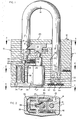
- Padlock body 10 is a padlock body composed of a ser: of laminations 11, 11 held together by a plurality c rivets, one of which is shown at 12.
- Padlock body I has a pair of opposite ends, 23, 24. Extending inws from end 23 is an elongated, receiving channel 14 w: which is normally received the long leg 15 of a shackl 16 having a short leg 17 which, when the shackle is in locked position, is received within a channel 18 extending inwardly into padlock body 10 from end 23.
- Shackle 16 is mounted for reciprocal movement relative to body 10, between an extended, open position, in whi short shackle leg 17 is outside body 10, and a plurali of depressed positions for the shackle, one of which i shown in Fig. 1.
- shackle long leg 15 normally remains within its receiving channel 14 in all positions of the shackle.
- a notch 21 for receiving the end 61 of a latch 22 urged a coil spring 29 toward channel 18.
- Latch end 61 engages notch 21 on short leg 17 when shackle 16 is ir: first of its depressed positions, shown in Fig. 1, wit short leg 17 inside channel 18.
- Located adjacent late 22 is the inner end 26 of a lock mechanism 25 operatec by a key insertable into a key slot (not shown) locate in the outer end 27 of lock mechanism 25, adjacent lod body end 24.
- Lock mechanism 25 is of conventional construction normally found in padlocks and need not t described here.
- latch 22 is moved away froi channel 18 causing latch end 61 to be withdrawn from engagement with notch 21, against the urging of latch spring 29.
- the structure which moves latch 22 in response to the operation of lock mechanism 25 is conventional in nature and need not be described here
- a flange 33 Located adjacent inner end 19 on long leg 15 is a flange 33 extending radially outwardly from leg 15. Outward movement of shackle 16, under the urging coil spring 30, is limited by the engagement of flange 33 with stop structure 32 extending into channel 14 fr one of the laminations 11. The engagement of flange 3 with stop structure 32 determines the extended positic of shackle 16. When the shackle is in its open, extended position, it may pivot about the axis of lone leg 15 between a first pivotal disposition in which short shackle leg 17 is aligned with its receiving channel 18 and a second pivotal disposition (e.g. 90° displaced from the first pivotal disposition) in whict the short shackle leg is completely clear of the lock body.
- a first pivotal disposition in which short shackle leg 17 is aligned with its receiving channel 18
- a second pivotal disposition e.g. 90° displaced from the first pivotal disposition
- Battery unit 35 comprises a plurality of batteries located within a U-shaped housing 38 comprising a printed circuit board which electrically connects together all of the batteries to function as unit.
- Board 38 is composed of non-electrically conductive material on which has been applied an electrically conductive printing to connect the batteries together in series.
- a signal emitting element in the form of a transducer 39 and a circuit board 40 each contained within respective housings 41, 42 formed in laminations 11, 11.
- transducer 39 When transducer 39 is activated, it generates an audible alarm sound which exists from the lock body through side sound ports 43 communicating with housing 41 and transducer 39.
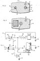
- Side sound ports 43 are located in intermediate laminations 11, 11 of lock body 10 as shown in Figs. 3-4, other laminations 11, 11 contain a plurality of sound ports 44 for conducting sound from transducer housing 41 to opposite ends 23, 24 of lock body 10 from which the sound may escape through openings 44.
- the signal emitting element may be a radio transmitter for emitting an inaudible radio signal which may be received locally or at a remote location where the inaudible signal activates an audible alarm or a light or other visual indicator.
- the embodiment described herein refers to the signal emitting element as a transducer; however, it should be understood that when reference is made to a transducer, a radio transmitter or a combination of transducer and radio transmitter may be employed in lieu of the transducer, except that at least a transducer must be employed when the lock body includes sound ports.
- Lock body 10 is ground in the electrical circuit.
- Long leg 15 is grounded during movement of shackle 16 by virtue of th contact between leg 15 and parts of laminations 11, 11 defining the walls of channel 14, e.g. the inside surface 75 of stop 32.
- This grounding contact between long leg 15 and lock body 10 is constant and continuou and occurs while the long leg is stationary (passive - contact) and while it is moving (sliding contact).
- the interior of channel 14 may be provided with a conductive wiper element (not shown) which is in constant contact with long leg 15 to conne the latter to ground.
- first switch element 45 is electrically connected to a resilient element 66 connected to the gate electrode 47 of a silicon rectifier 48 whose anod 49 and cathode 50 are connected across battery unit 35 in the circuit containing alarm-sounding transducer 39.
- Rectifier 48 is located on circuit board 40 and comprises a latch circuit activated when current flow through the rectifier is at a predetermined, sufficie I level. There is normally insufficient current flow through rectifier 48 to activate the latch.
- Second switch 46, 66 is kept closed when shackle 16 is in the depressed, closed position of Fig 1. More particularly, inner end 20 of short leg 17 presses downwardly on the outer end of a pin 51 guide within a channel 52 and having an inner end which presses element 66 of the second switch against eleme 46 to close the second switch when the shackle is in depressed, closed position of Fig. 1.
- the springab nature of resilient element 66 causes it to move away from element 46, pushing pin 51 axially outwardly wit channel 52 and opening the second switch.
- Second switch 46, 66 is closed when short 17 is inside channel 18 in the depressed position she in Fig. 1.
- the unlocking of lock mechanism 25 with key disengages latch 22 from notch 21 in short leg ll causing both legs of the shackle to be propelled outwardly by coil spring 30, and this immediately opr second switch 46, 66 before first switch 33, 45 clos ⁇ so that no alarm is sounded when the lock is opened : an authorized manner.
- Severing or forcing the shack leaves second switch 46, 66 closed because short leg remains in the depressed position of Fig. 1 while lo. leg 15 moves outwardly. In the case of a severance, long leg 15 is propelled outwardly by coil spring 30
- a sequenc steps which includes depressing long leg 15 inwardly against the urging of spring 30, to a second depressed position to close a third switch 53, 54 at the inner e: 31 of channel 14 followed by a release of the long leg to open the third switch.
- a permanent shut-off cannot occur unless short leg 17 is first moved outside of and pivoted away from lock body 10, because if short leg 17 is inside the lock, it will be engaged by latch 22 before long leg 17 can be depressed sufficiently to close the third switch.
- movii the short leg outside the lock body requires authorizer operation of the lock, as with a key.
- the third switch can be closed because long leg 15 or its severe stub will no longer be structurally connected to short leg 17. In such a case, however, a subsequent release of the severed, depressed long leg will only momentari shut-off the alarm which will then be re-actuated, as described below.
- the third switch comprises one contact eleme 53 located at inner end 31 of channel 14 and another contact element 54 at the inner end 19 of long leg 15.
- Contact element 53 is connected by a wire 76 to the negative electrode of battery 35 between the latter an latch circuit 48. Because contact element 54 is on th long shackle leg, it is connected through electrical ground to the positive electrode of the battery.
- Closing third switch 53, 54 completes a circuit connected to both sides of the battery, and this drain away from the latch circuit enough current to drop the current flow through the latch circuit below the level necessary to keep the latch circuit operating. As lor as the third switch 53, 54 is closed, the alarm will continue to sound because the third switch completes a circuit comprising battery 35 and alarm-sounding transducer 39.
- Coil spring 30 rests on multi-layer pad 64 composed of electrical insulating material.
- Switch element 53 extends upwardly through pad 64 from a thin film-like, electrically conductive layer 67 (Fig. 1) sandwiched between non-conductive layers of pad 64 and connected to wire 76.
- the alarm in the embodiment_c Fig. 1 can only be permanently shut off by an authoriz person who opens the lock with a key, to open second switch 46, 66, then pivots the short leg away from the lock body and then depresses long leg 15 to close the third switch, followed by the release of the long leg open the third switch.
- the latch circuit will remain latched allowing the alarm to continue even if second switch e 66 is opened.
- the latch circuit can only be rendered inoperable by dropping the current flow through the latch circuit below a predetermined level, and this condition will not be produced merely by opening the second switch. It can only be produced by closing the third switch.
- Closing the third switch can also be used to test the battery and the rest of the alarm circuit. 5 put the circuit in a test condition, the lock must be opened with a key, and short leg 17 must be withdrawn from the lock body and rotated out of alignment with : lock body (e.g., a 90° rotation). Then, long leg 15 t be manually depressed sufficiently to close the third switch at 53, 54, causing the alarm to begin by the flow of current through a circuit which completely bypasses latch circuit 48 (see Fig. 5).
- first switch 33, 45 will not reactuate the alarm because second switch 46, 66 is open due to short leg being outside the lock body.
- closing of first switch 33, 45 will not activate the alarm unless the second switch is closed at the same time.
- the lock may also contain an optional, additional circuit comprising a normally open fourth switch comprising an element 55 connected to electrical ground and located directly below resilient element 46 of the second switch so that further depression of shori leg 17 within channel 18 beyond its first depressed position will close a fourth switch defined by elements 46 and 55 while continuing to maintain second switch 46 66 in its normally closed position.
- Fourth switch 46, 55 is closed by depressing the shackle to a third depressed position which is more depressed than the shackle's first depressed position, in which only secon. switch 46, 66 is closed, but less depressed than the shackle's second depressed position in which third switch 53, 54 is closed.
- fourth switch element 55 and ground i a buffer resistance 56 (Fig. 5) located on circuit boar 40.
- fourth switch 46, 55 When fourth switch 46, 55 is closed, it completes circuit which connects gate electrode 47 of rectifier 4 to ground and thereby through the alarm components to the positive electrode on the battery, the negative electrode of which is connected to cathode 50 of the - rectifier.
- insufficient current flows through latcb circuit 48 to activate it to a latched condition when gate electrode 47 is connected to ground through fourtr switch 46, 55 and buffer resistance 56, but there is current flow through transducer 39 to sound the alarm.
- Switch elements 46, 55, 66 are all physically assembled into a unitary switch assembly 70 (Fig. 1) mounted within lock body 10 adjacent the inner end 69 the short leg's receiving channel 18.
- wires 77, 78 run from switch assembly 70 to circuit board 40 to connect switch elements 66 and 55 to gate electrode 47 and buffer resistance 56 respectively.
- Another wire 71 runs from switch element 46 on assembl: 70 to first switch element 45.
- Wires 72, 73 respectively connect the anode 49 and cathode 50 of rectifier 48 to transducer 39 and the cathode of batte 35 respectively.
- the alarm circuit m contain as a signal emitting element, in lieu of transducer 39 (Fig. 5), a radio transmitter 79 connect by an insulated wire 80 extending through an opening i lock body 10 to an antenna 81 disposed around the exterior of the lock body, e.g. embedded in a polyurethane skirt (not shown) surrounding lock body adjacent end 24 thereof.
- Radio transmitter 79 is of conventional construction and is commercially available.
- the signal emittin element may constitute a combination of both transduc 39 and radio transmitter 79. In all embodiments, the signal emitting element is activated, tested, turned and turned off as described above in connection with transducer 39.
- the lock comprise structure which prevents removal of battery cap 37 ar which renders the removal-preventing structure accessible to an authorized person only. More particularly, referring to Fig. 1, entry 36 to batter compartment 34 is closed by removable cap 37. Engagi the inner end of cap 37 is one end of a threaded memb 58 having, at its other end, a head 59 located at inr end 69 of the short leg's receiving channel 18. Memb 58 is a removable fastener which can be disengaged fr cap 37 solely by engaging a tool in fastener head 59. The engagement of cap 37 by fastener 58 prevents remc of cap 37 from entry 36.
- Fastener head 59 as well a the rest of fastener 58, is accessible solely through receiving channel 18.
- short leg 17 blocks access to fastener 58 when the short leg is in channe 18. Therefore, one may not remove fastener 58 until short leg 17 is outside the lock, and this can be accomplished only by authorized operation of the lock e.g. with a key. Absent disengagement of fastener 58 from cap 37, cap 37 cannot be removed and access to battery compartment 34 is not possible.
- Fig. 6 depicts an embodiment of present invention which eliminates the possibility t the audible alarm may be muted by a potential violat
- long le has an elongated, peripheral indentation 60 located an intermediate portion of the long leg.
- a lip 63 i disposed around the periphery of indentation 60 and extends in an axially outward direction at the inner 74 of the indentation.
- Latch 22 comprises, as in th embodiment of Fig. 1, first engaging means 61 for engaging notch 21 on short leg 17.
- latch 22 comprises second enga means 62 for engaging lip 63 when the shackle is in extended, open position.
- Latch 22 is mounted for reciprocal movement between a first position wherein latch is engageable with short leg 17 but not with leg 15 and a second position wherein the latch is engageable with long leg 15 but not short leg 17.
- C spring 29 normally urges latch 22 to its first posit
- latch 22 When lock mechanism 25 is operated with a by an authorized operator, latch 22 is moved to its second position, against the urging of coil spring : As the latch moves toward its second position it is disengaged from its engagement with short leg 17, ai coil spring 30 urges the entire shackle 16 towards extended open position.
- the extended open position for shackle 16 is determi by the engagement of second engaging means 62 on lat 22 with lip 63 at the inner end of indentation 60 or long leg 15.
- lip 63 When the shackle is depressed from its extended open position toward one of its depressed positions, lip 63 is disengaged from the latch's se l engaging means 62, and coil spring 29 urges latch 2 its first position.
- channel 14 whic receives long leg 15, is in communication with recess which contains alarm sounding transducer 39 (Fig. 2).
- Channel 14 has an open end 65 through which long leg le is received into the channel.
- the channel 14 and its open end 65 because they are in communication with transducer-containing recess 41, define a sound port for the audible alarm.
- long leg 15 wil be moved totally outside of channel 14 when there is a violation of the lock, either by severing shackle 16 o: by forcibly removing long leg 15 from channel 14. Whe: a violation occurs in either such manner, there has be no authorized operation of lock mechanism 25, so that latch 22 remains in its first position and there is th- no opportunity for the latch's second engaging means 6 to engage with lip 63 on indentation 60 in long leg 15. Accordingly, severance of shackle 16 will cause coil spring 30 to fully eject the stub of long leg 15 entirely out of channel 14, thereby creating the aforementioned open sound port.
- a violation is the form of a forced removal of the long leg from channel 14
- the sound port is opened when the long leg inner end 19 is forced outwardly through end 65 of the channel.
- movement of the long leg in outward direction causes a momentary closing of first switch 33, 45 while second switch 46, 66 remains close thereby actuating alarm sounding transducer 39 and activating latch circuit 48.
- the alarm ca only be shut off by inserting an elongated conductor element, such as piece of rod or the like, into chann E 14 until it contacts fourth switch element 53 and ther grounding the elongated conductor on a side wall of channel 14.
- the effect is to create a circuit which bypasses latch circuit 48, reducing the current flow therethrough below the activating level of the latch circuit.
- the elongated conductor element is th f disengaged from switch element 53, the alarm stops sounding.
Landscapes
- Burglar Alarm Systems (AREA)
Applications Claiming Priority (2)
| Application Number | Priority Date | Filing Date | Title |
|---|---|---|---|
| US692516 | 1985-01-18 | ||
| US06/692,516 US4811578A (en) | 1983-08-18 | 1985-01-18 | Padlock with tamper-actuated audible and/or inaudible alarm |
Publications (2)
| Publication Number | Publication Date |
|---|---|
| EP0189147A1 true EP0189147A1 (de) | 1986-07-30 |
| EP0189147B1 EP0189147B1 (de) | 1989-04-05 |
Family
ID=24780895
Family Applications (1)
| Application Number | Title | Priority Date | Filing Date |
|---|---|---|---|
| EP86100608A Expired EP0189147B1 (de) | 1985-01-18 | 1986-01-17 | Vorlegeschloss mit hörbarer und/oder nicht hörbarer Alarmvorrichtung, welche durch einen Stössel ausgelöst wird |
Country Status (4)
| Country | Link |
|---|---|
| US (1) | US4811578A (de) |
| EP (1) | EP0189147B1 (de) |
| CA (1) | CA1243372A (de) |
| DE (1) | DE3662707D1 (de) |
Cited By (9)
| Publication number | Priority date | Publication date | Assignee | Title |
|---|---|---|---|---|
| WO1995005515A1 (en) * | 1993-08-16 | 1995-02-23 | Dynatec Limited | Remote lock alarm |
| RU2135719C1 (ru) * | 1998-06-15 | 1999-08-27 | Шафиркин Давид Исаакович | Способ предотвращения несанкционированного разблокирования кодового узла устройства замкового типа |
| RU2175705C1 (ru) * | 2000-04-17 | 2001-11-10 | Шафиркин Давид Исаакович | Способ предотвращения несанкционированного разблокирования кодового узла устройства замкового типа (варианты) |
| WO2006030177A1 (en) * | 2004-09-14 | 2006-03-23 | Ivan Foti | Lock |
| EP1616068A4 (de) * | 2003-03-27 | 2009-12-23 | Acco Brands Inc | Physische sicherungsvorrichtung mit einem mit einem alarm verbundenen kabel für tragbare elektronische vorrichtung |
| GB2488987A (en) * | 2011-03-08 | 2012-09-19 | James Warwick Lucas | Lock unit with radio transmitter and separate alarm unit with receiver |
| WO2016058382A1 (zh) * | 2014-10-16 | 2016-04-21 | 深圳趣动智能科技有限公司 | 一种自行车智能防盗装置 |
| CN108643722A (zh) * | 2018-07-16 | 2018-10-12 | 芜湖市联网汇通电子科技有限公司 | 一种基于物联网的信息化管理的物流锁 |
| WO2023108234A1 (pt) * | 2021-12-16 | 2023-06-22 | Dib Ana Maria | Dispositivo de travamento inteligente, sistema e método para travamento e proteção de um objeto |
Families Citing this family (58)
| Publication number | Priority date | Publication date | Assignee | Title |
|---|---|---|---|---|
| US5408212A (en) * | 1992-09-18 | 1995-04-18 | Brio Corporation | Multi-mode combination alarm and locking apparatus for bicycles, motorcycles and the like |
| WO1994011603A1 (en) * | 1992-11-12 | 1994-05-26 | Garth Robert Chadfield | Padlock with tamper alarm |
| US5372019A (en) * | 1993-09-24 | 1994-12-13 | Hsiao; Yung-Chi | Automobile steering lock |
| US5404735A (en) * | 1994-03-15 | 1995-04-11 | Hsieh; Chen-Kuei | Padlock with built-in anti-theft alarm device |
| US5525964A (en) * | 1994-12-30 | 1996-06-11 | Ming; Wang S. | Electronic locking device |
| US5656996A (en) * | 1996-03-13 | 1997-08-12 | Global Associates, Ltd. | Electronic security bonding device |
| US5727405A (en) * | 1997-02-03 | 1998-03-17 | Cromwell; Daryl | Alarm padlock |
| ZA978882B (en) * | 1997-10-03 | 1998-06-24 | Waterson Chen | Padlock with replaceable key-operated lock core. |
| AU754316B2 (en) * | 1998-06-17 | 2002-11-14 | Waterson Chen | Padlock with replaceable key-operated lock core |
| US5896761A (en) * | 1998-07-08 | 1999-04-27 | Chen; Waterson | Padlock |
| JP2000085652A (ja) * | 1998-09-11 | 2000-03-28 | Iic:Kk | ロック用アラーム装置 |
| US6100802A (en) * | 1998-11-16 | 2000-08-08 | Nitro Security Systems, L.L.C. | Alarmed cable lock |
| US6940392B2 (en) * | 2001-04-24 | 2005-09-06 | Savi Technology, Inc. | Method and apparatus for varying signals transmitted by a tag |
| US6720888B2 (en) | 2000-09-07 | 2004-04-13 | Savi Technology, Inc. | Method and apparatus for tracking mobile devices using tags |
| US6542114B1 (en) | 2000-09-07 | 2003-04-01 | Savi Technology, Inc. | Method and apparatus for tracking items using dual frequency tags |
| US6765484B2 (en) | 2000-09-07 | 2004-07-20 | Savi Technology, Inc. | Method and apparatus for supplying commands to a tag |
| US6402181B1 (en) * | 2000-10-17 | 2002-06-11 | Lih Shya Lee | Trailer hitch and lock assembly |
| US6364339B1 (en) * | 2000-10-17 | 2002-04-02 | Lih Shya Lee | Trailer hitch and lock assembly |
| US7246511B1 (en) | 2000-12-21 | 2007-07-24 | Deming Zhu | Cable gunlock |
| SE522790C2 (sv) * | 2001-06-27 | 2004-03-09 | Aake Faektenmark | Anordning vid ett lås innefattande ett hänglås |
| US6747558B1 (en) | 2001-11-09 | 2004-06-08 | Savi Technology, Inc. | Method and apparatus for providing container security with a tag |
| US7126484B1 (en) | 2002-05-03 | 2006-10-24 | Luquire L Hanson | Snap-hook assemblies with added components |
| EP1371797A1 (de) * | 2002-05-13 | 2003-12-17 | European Community | Mehrzwecksiegel mit einem Schloss |
| US7236085B1 (en) | 2002-06-18 | 2007-06-26 | Smartlok Systems, Inc. | Lock with remotely activated lockout feature |
| US7301462B1 (en) | 2002-09-19 | 2007-11-27 | Tc License, Ltd. | Tamper resistant electronic tag |
| US6769277B1 (en) * | 2003-01-21 | 2004-08-03 | Wen-Kwei Chang | Structure of a locker |
| US20050103065A1 (en) * | 2003-11-19 | 2005-05-19 | Dennis Gordon K. | Protective cover for locking devices |
| US7198227B2 (en) * | 2004-06-10 | 2007-04-03 | Goodrich Corporation | Aircraft cargo locating system |
| US7010944B1 (en) | 2004-11-29 | 2006-03-14 | Chien Chih Chiu | Padlock having restoring mechanism |
| US7594416B2 (en) * | 2005-03-24 | 2009-09-29 | Bosin Sanford | Security device and methodology |
| US20060267728A1 (en) * | 2005-05-25 | 2006-11-30 | Kamrath Richard P | Padlock that generates a message |
| US20060288744A1 (en) * | 2005-06-28 | 2006-12-28 | William Smith | Alarm lock |
| US20070262594A1 (en) * | 2006-05-05 | 2007-11-15 | Tebco Pty Limited | Padlock with security seal |
| US20080018463A1 (en) * | 2006-07-18 | 2008-01-24 | Morrow Carl R | Device locking systems, lock trees, and lockout methods |
| US7543467B2 (en) * | 2006-09-19 | 2009-06-09 | Sheehan Thomas R | Portable lock wirelessly connectable to security system |
| MX2009013157A (es) * | 2007-06-04 | 2010-01-15 | Master Lock Co | Disposiciones seguras de montaje para un ensamble de seguro. |
| FR2951570B1 (fr) * | 2009-10-19 | 2012-06-29 | Thoonsen Trading | Dispositif antivol pour articles de vente |
| US7921682B1 (en) * | 2009-12-15 | 2011-04-12 | Jieh-Jung Chang | Padlock with alarm function |
| US20120186308A1 (en) | 2011-01-20 | 2012-07-26 | Abus August Bremicker Soehne Kg | Padlock for securing and monitoring a switch |
| EP2727097A1 (de) * | 2011-04-20 | 2014-05-07 | Xiao Hui Yang | Eas-etikett mit bügel |
| US9400150B2 (en) * | 2013-04-01 | 2016-07-26 | Yardarm Technologies, Inc. | Methods and systems for enhancing firearm safety through wireless network monitoring |
| US9958228B2 (en) | 2013-04-01 | 2018-05-01 | Yardarm Technologies, Inc. | Telematics sensors and camera activation in connection with firearm activity |
| US9395132B2 (en) | 2013-04-01 | 2016-07-19 | Yardarm Technologies, Inc. | Methods and systems for enhancing firearm safety through wireless network monitoring |
| US9404698B2 (en) * | 2013-04-01 | 2016-08-02 | Yardarm Technologies, Inc. | Methods and systems for enhancing firearm safety through wireless network monitoring |
| US9328535B2 (en) * | 2014-01-17 | 2016-05-03 | Kwikset Corporation | Padlock cylinder retention |
| CN104499850A (zh) * | 2014-12-14 | 2015-04-08 | 陈健全 | 微型挂锁 |
| CN206190039U (zh) * | 2016-10-26 | 2017-05-24 | 华数(厦门)信息有限公司 | 一种智能锁具 |
| CN106836989A (zh) * | 2017-01-20 | 2017-06-13 | 浙江浦江梅花锁业集团有限公司 | 一种挂锁 |
| US10030417B1 (en) * | 2017-01-26 | 2018-07-24 | Real Locks & Security Co., Ltd. | Induction type padlock |
| JP6582090B2 (ja) * | 2017-08-31 | 2019-09-25 | グン ジョン、ジェ | 南京錠 |
| US10995521B2 (en) * | 2018-06-27 | 2021-05-04 | Strattec Security Corporation | Linear lock |
| CN109113458A (zh) * | 2018-10-31 | 2019-01-01 | 深圳沃圣数码科技有限公司 | 一种指纹挂锁 |
| DE102019123469A1 (de) * | 2019-09-02 | 2021-03-04 | ABUS August Bremicker Söhne Kommanditgesellschaft | Tragbares Bügelschloss |
| CN215470913U (zh) * | 2021-05-21 | 2022-01-11 | 浙江普莱得电器股份有限公司 | 一种伸缩悬挂组件 |
| SE2230163A1 (sv) * | 2022-05-25 | 2023-11-26 | Gerhard Schultze | Låslarm |
| US20240218705A1 (en) * | 2022-10-07 | 2024-07-04 | Arturo Valdes Rudd | Portable lock operable in outdoor environments |
| USD1080354S1 (en) | 2024-01-12 | 2025-06-24 | Control Group Companies, LLC | Combination alarm tag |
| US12607044B2 (en) | 2024-01-12 | 2026-04-21 | Control Group Companies, LLC | Alarm tag with combination access |
Citations (2)
| Publication number | Priority date | Publication date | Assignee | Title |
|---|---|---|---|---|
| US3993987A (en) * | 1975-03-03 | 1976-11-23 | Stevens Edward C | Locking device having an integral alarm system |
| EP0064087B1 (de) * | 1981-04-30 | 1985-01-16 | Tsao-Keng Huang | Auftastsicheres Zylinderschloss |
Family Cites Families (13)
| Publication number | Priority date | Publication date | Assignee | Title |
|---|---|---|---|---|
| CA687974A (en) * | 1964-06-02 | J. Russell Fred | Removable cylinder | |
| US2070012A (en) * | 1935-08-09 | 1937-02-09 | Briggs & Stratton Corp | Padlock |
| FR919315A (fr) * | 1945-12-26 | 1947-03-05 | Cadenas massif automatique sans rivet ni sertissage | |
| US3597944A (en) * | 1970-01-27 | 1971-08-10 | Noel Litvin | Padlocks |
| US3772645A (en) * | 1972-01-20 | 1973-11-13 | T P S Inc Costa Mesa | Vehicle alarm system |
| US3828310A (en) * | 1972-06-05 | 1974-08-06 | Bike Alarm Ltd | Bicycle theft alarm |
| US3824540A (en) * | 1972-07-27 | 1974-07-16 | K Smith | Bicycle lock and alarm apparatus |
| US3824541A (en) * | 1972-11-15 | 1974-07-16 | R Nolan | Anti-theft device for bicycles and the like |
| CA962079A (en) * | 1973-03-28 | 1975-02-04 | Leo E. Van Lahr | Padlock |
| US3879721A (en) * | 1973-09-27 | 1975-04-22 | Robert A Yereance | Lock having flexible shackle with severance alarm |
| US4057986A (en) * | 1976-07-19 | 1977-11-15 | Sarah Zolke | Self-contained alarm lock |
| JPS5829090A (ja) * | 1981-08-13 | 1983-02-21 | 本田技研工業株式会社 | ワイヤロツク切断アラ−ム装置 |
| US4556878A (en) * | 1983-05-11 | 1985-12-03 | International Business Machines Corp. | Display of graphics using a non-all points addressable display |
-
1985
- 1985-01-18 US US06/692,516 patent/US4811578A/en not_active Expired - Fee Related
-
1986
- 1986-01-17 CA CA000499776A patent/CA1243372A/en not_active Expired
- 1986-01-17 EP EP86100608A patent/EP0189147B1/de not_active Expired
- 1986-01-17 DE DE8686100608T patent/DE3662707D1/de not_active Expired
Patent Citations (2)
| Publication number | Priority date | Publication date | Assignee | Title |
|---|---|---|---|---|
| US3993987A (en) * | 1975-03-03 | 1976-11-23 | Stevens Edward C | Locking device having an integral alarm system |
| EP0064087B1 (de) * | 1981-04-30 | 1985-01-16 | Tsao-Keng Huang | Auftastsicheres Zylinderschloss |
Cited By (14)
| Publication number | Priority date | Publication date | Assignee | Title |
|---|---|---|---|---|
| GB2283050A (en) * | 1993-08-16 | 1995-04-26 | Dynatec Ltd | Remote lock alarm |
| WO1995005515A1 (en) * | 1993-08-16 | 1995-02-23 | Dynatec Limited | Remote lock alarm |
| RU2135719C1 (ru) * | 1998-06-15 | 1999-08-27 | Шафиркин Давид Исаакович | Способ предотвращения несанкционированного разблокирования кодового узла устройства замкового типа |
| RU2175705C1 (ru) * | 2000-04-17 | 2001-11-10 | Шафиркин Давид Исаакович | Способ предотвращения несанкционированного разблокирования кодового узла устройства замкового типа (варианты) |
| EP1616068A4 (de) * | 2003-03-27 | 2009-12-23 | Acco Brands Inc | Physische sicherungsvorrichtung mit einem mit einem alarm verbundenen kabel für tragbare elektronische vorrichtung |
| US7752874B2 (en) | 2004-09-14 | 2010-07-13 | Ivan Foti | Lock |
| WO2006030177A1 (en) * | 2004-09-14 | 2006-03-23 | Ivan Foti | Lock |
| AU2005283983B2 (en) * | 2004-09-14 | 2010-11-25 | Xena Ip Holdings Limited | Lock |
| KR101124405B1 (ko) * | 2004-09-14 | 2012-03-20 | 이반 포티 | 자물쇠 |
| GB2488987A (en) * | 2011-03-08 | 2012-09-19 | James Warwick Lucas | Lock unit with radio transmitter and separate alarm unit with receiver |
| WO2016058382A1 (zh) * | 2014-10-16 | 2016-04-21 | 深圳趣动智能科技有限公司 | 一种自行车智能防盗装置 |
| US9868483B2 (en) | 2014-10-16 | 2018-01-16 | Shenzhen Smart Riding Intelligence Technology Co., Ltd | Intelligent anti-theft device for bicycles |
| CN108643722A (zh) * | 2018-07-16 | 2018-10-12 | 芜湖市联网汇通电子科技有限公司 | 一种基于物联网的信息化管理的物流锁 |
| WO2023108234A1 (pt) * | 2021-12-16 | 2023-06-22 | Dib Ana Maria | Dispositivo de travamento inteligente, sistema e método para travamento e proteção de um objeto |
Also Published As
| Publication number | Publication date |
|---|---|
| US4811578A (en) | 1989-03-14 |
| DE3662707D1 (en) | 1989-05-11 |
| CA1243372A (en) | 1988-10-18 |
| EP0189147B1 (de) | 1989-04-05 |
Similar Documents
| Publication | Publication Date | Title |
|---|---|---|
| US4811578A (en) | Padlock with tamper-actuated audible and/or inaudible alarm | |
| US5727405A (en) | Alarm padlock | |
| US5587702A (en) | Padlock with tamper alarm | |
| US6275141B1 (en) | Single-key security system | |
| US4556872A (en) | Padlock with tamper alarm | |
| US5925861A (en) | Security door lock arrangement with magnetically operated switch in the closed door position | |
| US5836002A (en) | Anti-theft device | |
| EP0518873B1 (de) | Sicherheitsanordnung | |
| CN103774922B (zh) | 包括警报器的圆柱锁 | |
| US3993987A (en) | Locking device having an integral alarm system | |
| US3444546A (en) | Protection system | |
| US10494836B2 (en) | Bored lock occupancy indicator | |
| WO2008038263A2 (en) | Key safe apparatus and method | |
| FI92514C (fi) | Sähköiset avainlukot | |
| US3851325A (en) | Lock and alarm | |
| WO2001086097A2 (en) | Wireless electromechanical lock | |
| CN202990624U (zh) | 用于家居的防盗锁装置 | |
| JP3898413B2 (ja) | ドア | |
| CN202899809U (zh) | 用于智能家居的防盗锁装置 | |
| US20170241163A1 (en) | Lock assembly with detection function | |
| CN223689480U (zh) | 一种智能u型锁 | |
| CN2326700Y (zh) | 多功能自控报警防盗门锁 | |
| CN101270630A (zh) | 具有被撬报警功能的防盗门 | |
| US20020047312A1 (en) | Locking device for lock | |
| KR200287459Y1 (ko) | 보안 겸용의 비상문 |
Legal Events
| Date | Code | Title | Description |
|---|---|---|---|
| PUAI | Public reference made under article 153(3) epc to a published international application that has entered the european phase |
Free format text: ORIGINAL CODE: 0009012 |
|
| AK | Designated contracting states |
Kind code of ref document: A1 Designated state(s): DE FR GB IT |
|
| 17P | Request for examination filed |
Effective date: 19861203 |
|
| 17Q | First examination report despatched |
Effective date: 19871102 |
|
| GRAA | (expected) grant |
Free format text: ORIGINAL CODE: 0009210 |
|
| AK | Designated contracting states |
Kind code of ref document: B1 Designated state(s): DE FR GB IT |
|
| PG25 | Lapsed in a contracting state [announced via postgrant information from national office to epo] |
Ref country code: IT Free format text: LAPSE BECAUSE OF FAILURE TO SUBMIT A TRANSLATION OF THE DESCRIPTION OR TO PAY THE FEE WITHIN THE PRESCRIBED TIME-LIMIT;WARNING: LAPSES OF ITALIAN PATENTS WITH EFFECTIVE DATE BEFORE 2007 MAY HAVE OCCURRED AT ANY TIME BEFORE 2007. THE CORRECT EFFECTIVE DATE MAY BE DIFFERENT FROM THE ONE RECORDED. Effective date: 19890405 Ref country code: FR Free format text: THE PATENT HAS BEEN ANNULLED BY A DECISION OF A NATIONAL AUTHORITY Effective date: 19890405 |
|
| REF | Corresponds to: |
Ref document number: 3662707 Country of ref document: DE Date of ref document: 19890511 |
|
| EN | Fr: translation not filed | ||
| PGFP | Annual fee paid to national office [announced via postgrant information from national office to epo] |
Ref country code: DE Payment date: 19900117 Year of fee payment: 5 |
|
| PLBE | No opposition filed within time limit |
Free format text: ORIGINAL CODE: 0009261 |
|
| STAA | Information on the status of an ep patent application or granted ep patent |
Free format text: STATUS: NO OPPOSITION FILED WITHIN TIME LIMIT |
|
| 26N | No opposition filed | ||
| PG25 | Lapsed in a contracting state [announced via postgrant information from national office to epo] |
Ref country code: DE Effective date: 19911001 |
|
| PGFP | Annual fee paid to national office [announced via postgrant information from national office to epo] |
Ref country code: GB Payment date: 19930108 Year of fee payment: 8 |
|
| PG25 | Lapsed in a contracting state [announced via postgrant information from national office to epo] |
Ref country code: GB Effective date: 19940117 |
|
| GBPC | Gb: european patent ceased through non-payment of renewal fee |
Effective date: 19940117 |