EP0189132A2 - Appareil à clavier avec contacts à action brusque magnétique - Google Patents
Appareil à clavier avec contacts à action brusque magnétique Download PDFInfo
- Publication number
- EP0189132A2 EP0189132A2 EP86100557A EP86100557A EP0189132A2 EP 0189132 A2 EP0189132 A2 EP 0189132A2 EP 86100557 A EP86100557 A EP 86100557A EP 86100557 A EP86100557 A EP 86100557A EP 0189132 A2 EP0189132 A2 EP 0189132A2
- Authority
- EP
- European Patent Office
- Prior art keywords
- contacts
- actuator
- contact
- actuator plate
- plate
- Prior art date
- Legal status (The legal status is an assumption and is not a legal conclusion. Google has not performed a legal analysis and makes no representation as to the accuracy of the status listed.)
- Granted
Links
- 239000000463 material Substances 0.000 claims abstract description 11
- 230000000994 depressogenic effect Effects 0.000 claims description 7
- 239000004020 conductor Substances 0.000 claims description 4
- 239000012858 resilient material Substances 0.000 claims description 2
- 229910000831 Steel Inorganic materials 0.000 abstract description 9
- 239000010959 steel Substances 0.000 abstract description 9
- 239000004033 plastic Substances 0.000 abstract description 7
- 229920003023 plastic Polymers 0.000 abstract description 7
- 238000000034 method Methods 0.000 abstract description 4
- 238000000465 moulding Methods 0.000 abstract description 3
- 239000004593 Epoxy Substances 0.000 abstract description 2
- 239000004952 Polyamide Substances 0.000 abstract description 2
- 230000008901 benefit Effects 0.000 abstract description 2
- 230000002596 correlated effect Effects 0.000 abstract description 2
- 230000005670 electromagnetic radiation Effects 0.000 abstract description 2
- 239000011810 insulating material Substances 0.000 abstract description 2
- 229920002647 polyamide Polymers 0.000 abstract description 2
- 230000005291 magnetic effect Effects 0.000 description 12
- 230000009471 action Effects 0.000 description 8
- 238000011109 contamination Methods 0.000 description 4
- 230000006870 function Effects 0.000 description 4
- 230000007246 mechanism Effects 0.000 description 4
- 229910000639 Spring steel Inorganic materials 0.000 description 2
- 238000004140 cleaning Methods 0.000 description 2
- 238000003754 machining Methods 0.000 description 2
- 238000004519 manufacturing process Methods 0.000 description 2
- 239000002991 molded plastic Substances 0.000 description 2
- 230000036961 partial effect Effects 0.000 description 2
- 125000006850 spacer group Chemical group 0.000 description 2
- 229910001220 stainless steel Inorganic materials 0.000 description 2
- 239000010935 stainless steel Substances 0.000 description 2
- 239000000126 substance Substances 0.000 description 2
- 238000005452 bending Methods 0.000 description 1
- 150000001875 compounds Chemical class 0.000 description 1
- 230000000875 corresponding effect Effects 0.000 description 1
- 238000005260 corrosion Methods 0.000 description 1
- 230000007797 corrosion Effects 0.000 description 1
- 239000013078 crystal Substances 0.000 description 1
- 238000013016 damping Methods 0.000 description 1
- 238000013479 data entry Methods 0.000 description 1
- 238000010586 diagram Methods 0.000 description 1
- -1 dirt Substances 0.000 description 1
- 239000000428 dust Substances 0.000 description 1
- 230000005294 ferromagnetic effect Effects 0.000 description 1
- 229920002457 flexible plastic Polymers 0.000 description 1
- 230000002427 irreversible effect Effects 0.000 description 1
- 230000000670 limiting effect Effects 0.000 description 1
- 239000007788 liquid Substances 0.000 description 1
- 230000002829 reductive effect Effects 0.000 description 1
- 230000001105 regulatory effect Effects 0.000 description 1
- 230000004044 response Effects 0.000 description 1
- 230000002441 reversible effect Effects 0.000 description 1
- 230000000630 rising effect Effects 0.000 description 1
- 239000000758 substrate Substances 0.000 description 1
Images


Classifications
-
- H—ELECTRICITY
- H01—ELECTRIC ELEMENTS
- H01H—ELECTRIC SWITCHES; RELAYS; SELECTORS; EMERGENCY PROTECTIVE DEVICES
- H01H13/00—Switches having rectilinearly-movable operating part or parts adapted for pushing or pulling in one direction only, e.g. push-button switch
- H01H13/70—Switches having rectilinearly-movable operating part or parts adapted for pushing or pulling in one direction only, e.g. push-button switch having a plurality of operating members associated with different sets of contacts, e.g. keyboard
- H01H13/78—Switches having rectilinearly-movable operating part or parts adapted for pushing or pulling in one direction only, e.g. push-button switch having a plurality of operating members associated with different sets of contacts, e.g. keyboard characterised by the contacts or the contact sites
- H01H13/80—Switches having rectilinearly-movable operating part or parts adapted for pushing or pulling in one direction only, e.g. push-button switch having a plurality of operating members associated with different sets of contacts, e.g. keyboard characterised by the contacts or the contact sites characterised by the manner of cooperation of the contacts, e.g. with both contacts movable or with bounceless contacts
-
- H—ELECTRICITY
- H01—ELECTRIC ELEMENTS
- H01H—ELECTRIC SWITCHES; RELAYS; SELECTORS; EMERGENCY PROTECTIVE DEVICES
- H01H13/00—Switches having rectilinearly-movable operating part or parts adapted for pushing or pulling in one direction only, e.g. push-button switch
- H01H13/70—Switches having rectilinearly-movable operating part or parts adapted for pushing or pulling in one direction only, e.g. push-button switch having a plurality of operating members associated with different sets of contacts, e.g. keyboard
- H01H13/7006—Switches having rectilinearly-movable operating part or parts adapted for pushing or pulling in one direction only, e.g. push-button switch having a plurality of operating members associated with different sets of contacts, e.g. keyboard comprising a separate movable contact element for each switch site, all other elements being integrated in layers
-
- H—ELECTRICITY
- H03—ELECTRONIC CIRCUITRY
- H03M—CODING; DECODING; CODE CONVERSION IN GENERAL
- H03M11/00—Coding in connection with keyboards or like devices, i.e. coding of the position of operated keys
- H03M11/20—Dynamic coding, i.e. by key scanning
-
- H—ELECTRICITY
- H01—ELECTRIC ELEMENTS
- H01H—ELECTRIC SWITCHES; RELAYS; SELECTORS; EMERGENCY PROTECTIVE DEVICES
- H01H1/00—Contacts
- H01H1/12—Contacts characterised by the manner in which co-operating contacts engage
- H01H1/14—Contacts characterised by the manner in which co-operating contacts engage by abutting
- H01H1/24—Contacts characterised by the manner in which co-operating contacts engage by abutting with resilient mounting
- H01H1/26—Contacts characterised by the manner in which co-operating contacts engage by abutting with resilient mounting with spring blade support
-
- H—ELECTRICITY
- H01—ELECTRIC ELEMENTS
- H01H—ELECTRIC SWITCHES; RELAYS; SELECTORS; EMERGENCY PROTECTIVE DEVICES
- H01H2201/00—Contacts
- H01H2201/004—Wiping action
-
- H—ELECTRICITY
- H01—ELECTRIC ELEMENTS
- H01H—ELECTRIC SWITCHES; RELAYS; SELECTORS; EMERGENCY PROTECTIVE DEVICES
- H01H2203/00—Form of contacts
- H01H2203/024—Convex contact surface
-
- H—ELECTRICITY
- H01—ELECTRIC ELEMENTS
- H01H—ELECTRIC SWITCHES; RELAYS; SELECTORS; EMERGENCY PROTECTIVE DEVICES
- H01H2205/00—Movable contacts
-
- H—ELECTRICITY
- H01—ELECTRIC ELEMENTS
- H01H—ELECTRIC SWITCHES; RELAYS; SELECTORS; EMERGENCY PROTECTIVE DEVICES
- H01H2209/00—Layers
- H01H2209/024—Properties of the substrate
- H01H2209/026—Properties of the substrate metallic
-
- H—ELECTRICITY
- H01—ELECTRIC ELEMENTS
- H01H—ELECTRIC SWITCHES; RELAYS; SELECTORS; EMERGENCY PROTECTIVE DEVICES
- H01H2215/00—Tactile feedback
- H01H2215/028—Tactile feedback alterable
-
- H—ELECTRICITY
- H01—ELECTRIC ELEMENTS
- H01H—ELECTRIC SWITCHES; RELAYS; SELECTORS; EMERGENCY PROTECTIVE DEVICES
- H01H2217/00—Facilitation of operation; Human engineering
- H01H2217/006—Different feeling for different switch sites
-
- H—ELECTRICITY
- H01—ELECTRIC ELEMENTS
- H01H—ELECTRIC SWITCHES; RELAYS; SELECTORS; EMERGENCY PROTECTIVE DEVICES
- H01H2217/00—Facilitation of operation; Human engineering
- H01H2217/02—After travel
-
- H—ELECTRICITY
- H01—ELECTRIC ELEMENTS
- H01H—ELECTRIC SWITCHES; RELAYS; SELECTORS; EMERGENCY PROTECTIVE DEVICES
- H01H2221/00—Actuators
- H01H2221/036—Return force
- H01H2221/04—Return force magnetic
-
- H—ELECTRICITY
- H01—ELECTRIC ELEMENTS
- H01H—ELECTRIC SWITCHES; RELAYS; SELECTORS; EMERGENCY PROTECTIVE DEVICES
- H01H2225/00—Switch site location
- H01H2225/012—Switch site location normally closed
-
- H—ELECTRICITY
- H01—ELECTRIC ELEMENTS
- H01H—ELECTRIC SWITCHES; RELAYS; SELECTORS; EMERGENCY PROTECTIVE DEVICES
- H01H2229/00—Manufacturing
- H01H2229/024—Packing between substrate and membrane
-
- H—ELECTRICITY
- H01—ELECTRIC ELEMENTS
- H01H—ELECTRIC SWITCHES; RELAYS; SELECTORS; EMERGENCY PROTECTIVE DEVICES
- H01H2229/00—Manufacturing
- H01H2229/034—Positioning of layers
-
- H—ELECTRICITY
- H01—ELECTRIC ELEMENTS
- H01H—ELECTRIC SWITCHES; RELAYS; SELECTORS; EMERGENCY PROTECTIVE DEVICES
- H01H2229/00—Manufacturing
- H01H2229/042—Snap coupling; Snap mounting
-
- H—ELECTRICITY
- H01—ELECTRIC ELEMENTS
- H01H—ELECTRIC SWITCHES; RELAYS; SELECTORS; EMERGENCY PROTECTIVE DEVICES
- H01H2239/00—Miscellaneous
- H01H2239/004—High frequency adaptation or shielding
-
- H—ELECTRICITY
- H01—ELECTRIC ELEMENTS
- H01H—ELECTRIC SWITCHES; RELAYS; SELECTORS; EMERGENCY PROTECTIVE DEVICES
- H01H2239/00—Miscellaneous
- H01H2239/008—Static electricity considerations
Definitions
- This invention relates to keyboards for alphanumeric and data entry applications in general and specifically to magnetically detented snap actuators and keyboard apparatus incorporating the same.
- Magnetic snap actuation keyboards are widely known since the breakaway characteristic of magnetically detented devices has often been exploited in patent literature to provide the sudden snap actuation that is desirable for keyboard applications.
- the designs have been of two general sorts: either an actuator plate is broken free from a fixed magnet or a movable magnet is broken free from a fixed plate.
- Such a design that has some similarities to the present invention was published in the IBM Technical Disclosure Bulletin, Vol. 26, No. 6, November, 1983, pages 2888-2890.
- these actuators did not have individual contact fingers, a wiping action contact, simplified keyboard structure or a high voltage open collector easily sensed output.
- prior art magnetically actuated or detented keyboards have usually involved numerous separate pieces in the form of individual magnets, individual assembly steps to carefully position magnets for each key position, complicated wiring or contact structures that are separate from the actuator itself and other numerous cost and complexity increasing aspects that are less desirable.
- Yet another object of the present invention is to provide an improved magnetically detented keyboard in which easily mass produced and simplified assembly elements can be utilized.
- a magnetically detented actuator comprises a pair of stationery physically separate electrical contacts, permanent magnet means adjacent to and laterally spaced from the contacts, and an actuator plate of magnetically permeable, electrically conductive, resilient material positioned to lie in contact with the magnet means with electrically conductive integral spring contact arms in electrical contact with the stationery contacts, the actuator plate having a part extending laterally and upwardly there trom and positioned to be depressed to provide a moment tending to separate the actuator plate from the magnet means; and having a locating aperture for locating the actuator so that the electrically conductive integral spring contact arms align with the stationary contacts.
- the invention includes keyboard apparatus comprising a baseplate having a plurality of upstanding locator posts, a circuit card having apertures therein to align the circuit card over the locator posts, a plurality of pairs of spaced station in any electrical contacts thereon and a plurality of conductor lines thereon connected to the contacts, a plurality of permanent magnets mounted on the circuit card adjacent to and spaced from the paris of electrical contacts, a plurality of angled magnetically permeable electrically conductive resilient actuator plates, each plate having a locating aperture therein for placement over a locator post, and being divided to form a pair of integral spring contact arms with electrical contact areas aligned with a respective pair of contacts on the circuitboard to electrically connect the contacts together through the actuator plate, and a part extending laterally and upwardly therefrom, and a plurality of key buttons by which the actuator plate parts may be depressed to provide a moment to separate the actuator plate from the magnet.
- the snap actuator is an angled magnetically permeable plate.
- One leg of the angled plate is attracted to a strip magnet placed on a circuitboard.
- This particular portion of the plate also has two spring fingers that make contact with spherical or domed contacts on the circuitboard or, in the alternative, have formed dome portions in the end of each finger for contacting flat contacts on the circuitboard so that a wiping action that is resistant to contamination results.
- the other leg of the angled plate serves as a lever arm to which key button pressure is applied.
- the angle between the plates or the edge of the angled plate serves as a lever arm to which key button pressure is applied.
- the angle between the plates or the edge of the strip magnet serves as a fulcrum for pivoting the plate under the influence of key pressure.
- key pressure has built up sufficiently, the magnetic attraction is substantially broken and the angled plate is suddenly released, thereby breaking contact with the circuit contacts and allowing the circuit voltage to be sensed.
- the actuator plate is contacting the contacts, electrically shorting them together, and one of the contacts is connected to ground potential so that no output is present.
- All of the contacts and interconnecting circuitry can be formed using printed circuit techniques on a circuitboard and the magnets can be in the form of plastic compound strip magnets which are later laid down on top of the circuitboard.
- the individual actuator plates can be easily positioned over locator posts rising up from a baseplate at regular interval spacings and the posts can also be used for registering the position of the printed circuit so that the individual actuators registered on their posts are also precisely positioned for the circuitry on the circuitboard.
- a flap of material may be die cut or slit and formed out of a portion of the actuator plate that is in contact with the magnet and this can act as a stop for limiting the amount of the excursion that the moving plate experiences in response to downward pressure on the actuating lever portion of the angled plate.
- the positioning or baseplate 1 may be formed of plastic or steel or other material as desired. Steel offers the advantage of electromagnetic radiation shielding, electrical grounding possibilities and high structural integrity but molded and/or plated plastics can offer much the same with the exception of the same high physical strength.
- a number of individual locator posts 2 of which one appears in Figure 1A may be formed integrally with the baseplate 1 by slitting and stamping in the case of a steel or metallic plate or by molding in the case of plastic. The posts 2 would be spaced at regular intervals correlated with the desired keybutton spacings and positions in the assembled keyboard.
- a circuitboard or circuit card 3 of insulating material such as an epoxy laminate, sheet polyamide or the like may be employed.
- An aperture 4 in the circuit card 3 facilitates registering the circuit card precisely over the locator posts 2 on the baseplate 1.
- Circuitry 12 in the desired artwork pattern may be formed using well known techniques on the surface of the circuitboard 3.
- a contact 11 which may be spherical as shown in Fig. 1A or hemispherical or any other generally dome shape may be attached to the circuitry 12 as a contact. Two of these contacts are utilized for each key actuator position, but only one is shown in Figure 1A, lying directly behind it.
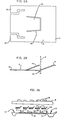
- a snap actuator 5 in the form of an angled thin spring steel plate comprises a body slit to form two side arms 10 and a central angled tongue or tab 13, leaving an angled end extension or lever arm leg 6 is illustrated in cross section.
- the part 2 passes through a slit 14 (Fig. 2A) which forms the tongue or tab 13 which serves as a stop against post 2 when actuator 5 is moved as shown in Figure 1B.
- the locator post 2 in the slit 14 locates the actuator 5 that the side mars 10 align with the contacts 11 at each key position.
- a top frame 9 (part of which only appears in Figs. 1A and 1B) is apertured to receive key buttons 8 (of which only one appears in Figs. 1A and 1B) of which a key stem 7 is arranged to slide in a housing 9 which may form a part of the top frame so that when pressure is applied to the top of a key button 8, the bottom of stem 7 will contact the lever arm leg 6 of the actuator plate 5.
- a permanent magnet 16 is placed on top of the circuitboard 3 and overlies the circuitry 12 as shown.
- the magnet 16 may be a molded plastic permanent magnet material well known in the industry as flexible plastic strip magnets and it may be adhesively applied to lie between the contact balls 11 and the locator posts 2 in elongated strips ( Figures 3A to 3C). By magnetic attraction, the magnet 16 will attract the actuator plate 5 which must be made of a ferromagnetic steel or stainless steel or some other magnetically permeable material. Magnetic type stainless steel is preferred since it resists corrosion and contamination better than ordinary steels.
- Figure 1B illustrates the elements of Figure 1A when the key button 8 has been fully depressed to the point that break away of the actuator plate 5 from the magnet 16 has occurred and the stop tongue 13 has been brought into abuttment with the locator post 2.
- key button 8 Continued downward pressure on key button 8 will flex leg 6 providing the necessary overtravel so desirable in key mechanisms. Eventually, the leg 6 will contact the top of the circuitboard and a high resistance to increased deflection will immediately result.
- a logic level high voltage such a 5-volt DC is supplied to all of the key positions in a keyboard so that for each key position such as illustrated in Figure lA, one of the contact balls 11 is supplied with 5-volt potential.
- the other ball 11 is connected to ground and interconnection between the two balls at each key location is via the actuator plate 5 with its integral contact spring fingers 10.
- FIG 2A a plan view of an individual actuator plate 5 is shown. It may be seen that the plate is actually one integral piece of material that has been formed by stamping or slitting or chemical machining or other operation of similar sort.
- a slit 14 frees a tongue or tab portion 13 to be bent upward at an angle from the main body 5 to serve as the stop post as shown in Figure lA, 1B and 2B.
- Individual contact spring fingers 10 are formed in the end of the actuator plate 5 as illustrated and the lever arm 6 is formed by bending the plate 5 at location 15 as shown in Figure 2B.
- a total assembly of key positions in a typical keyboard may be easily manufactured utilizing the structure as shown in Figures 1A and 1B for the preferred embodiment.
- a baseplate 1 is formed with appropriate locating posts 2.
- a circuitboard with die cut apertures corresponding to the spacing of the locating posts and the baseplate 1 is positioned on top of the baseplate and the magnets 16 are laid in place over the top of the circuitboard.
- individual actuators 5 are positioned over the locator posts 2 which protrude through the individual slots 14 in each actuator 5. This precisely locates the actuator plates 5 so that the spring fingers 10 will align with the contact balls 11 at each key position.
- a keyboard frame top 9 containing numerous key buttons can be placed over the entire structure and assembly is complete.
- the actuator 5 is made from a single piece of material and formed by stamping or slitting or chemical machining and the like.
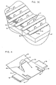
- Figure 3A illustrates a schematic horizontal exploded section of a second preferred embodiment of the invention.
- the base plate 1 is made of molded plastic material that can be sensitized and have plated directly on it the entire circuit pattern and contacts 11 and 12.
- Individual strip magnet 16 can then be laid down adjacent the locator posts 2 and the actuator plates 5 put in position as previously disclosed.
- the overall unitary top cover and frame 9 with individual key actuator buttons 8 can then be dropped in place and located over locating and snap fit posts 17 to complete the assembly.
- Figure 3B illustrates pictorially the assembly steps and dramatically illustrates the simplicity of structure and manufacturing steps involved for this embodiment.
- the baseplate 1 is actually the lower housing of the overall keyboard and has integrally molded with it the contacts 11, the locating posts 2, and the circuitry 12 interconnecting the various contacts as necessary.
- the form of the individual strip magnets is shown and the individual actuator plates 5 in a typical key button array are also shown.
- the upper housing and frame portion 9 holds the individual tops of key 8 as depicted.
- Figure 3C illustrates an enlarged partial pictorial view of a section of the assembled structure from Figures 3A and 3B. It may be observed that the individual locator posts 2 serve the purpose of providing a registration point for registering the magnet 16 as well as providing the location points for the individual actuators 5 (not shown in Figure 3C).
- the individual circuit lines 18 making up the printed circuit 12 are plated directly in place on the base plate or frame 1 as are the individual contacts 11 associated with each key position. Only one contact at each key position is supplied with a conductor 18, the other contact 11 being connected to ground through a common connection to the base of frame 1 (not shown).
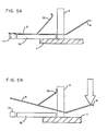
- FIG 4 an enlarged pictorial view of one assembled actuator plate 5 in position over a locator post 2 and having spring finger contacts 10 engaging the contacts 11 when the plate 5 is attracted to magnet 16 is illustrated.
- Figures 5A and 5B illustrate diagramatically the structure as shown in Figure 4 in two stages of actuation.
- the actuator is in its rest position and spring finger contacts 10 are in electrical and physical contact with the individual contacts 11 that are connected as previously described to the circuitry 12, not shown.
- the actuator plate 5 is attracted by magnet 16 and the stop post 13, preferably bent upward at an angle of approximately 55°, is out of contact with the locator post 2.
- the angled upward lever arm 6 which is an integral part of the actuator plate 5 may be supported at its fulcrum point as shown or may be fulcrummed on the post 2.
- beam spring or spring finger actuators of the type depicted in the figures can be formed either with flat fingers 10 or with a dome portion in the end of each finger 10. If the end of the fingers 10 is formed into a hemispherical pad, the keyboard may be made with flat contact pads 11 on the circuitboard 3. While this has not been illustrated, its variation will be apparent to those of skill in the art.
- the hemispherical contact on the circuitboard which is the alternative illustrated in the figures, has some desirable attributes beyond that of a flat contact 11 in that actual contact point is elevated above the substrate of the frame or circuitboard so that any contamination in the form of dust, dirt, or liquid has a chance to run off from the actual contact points.
- a wiping action is achieved during actuation by making the height of the actual contact point slightly greater than the thickness of a magnet 16. This causes a slight deflection in the spring finger ends 10 of the actuator 5 as depicted in the figures.
- Overall assembly is greatly simplified since the base plate or positioning plate 1 can have the locator post 2 integrally formed in it by stamping or molding.
- the steel actuators 5 can be located over the posts as can the circuitboard 3 and the actuators will be held in place by the magnet strip 16 so that the unfinished assembly may be easily handled from station to station and have the entire top cover or frame 9 with individual buttons 8 and return springs (not shown) dropped in place.
- the spring lever arm 6 of individual actuator plates 5 may serve as the key button return spring.
- the overall design is also suited to an overlay style of keyboard if the baseplate 1 is used actually as a top cover and the tabs or posts 2 are bend downward.
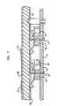
- a nomenclature sheet can be placed over the ends 6 of the actuator plates 5 as is depicted in Figure 7.
- an overlay sheet 50 with individual nomenclature 51 that can be supported on a top plate 52 having an aperture 53 aligned with the lever arm 6 of an actuator plate 5 attracted to a magnet 16 on a circuitboard 3 can be built.
- the contact arm 10 is shown of the formed spring finger type to make contact with a flat contact 11 on the circuitboard 3.
- a spacer post 54 keeps the top plate 52 at the desired spacing above the baseplate or circuitboard 3.
- the touch or sense of feel provided can be easily varied by varying the width of the actuator plates 5 that are in contact with the magnet 16.
- the size of the magnetic strip 16 can be modified to offer a menu of different key touch and sense options for an individual preferred result, i.e., high, medium or low force keyboard actuation.
- the contacts 10 and 11 can be made between the stop post 13 and the locator post 2 to form a normally opened switch structure instead of a normally closed one such as that illustrated in the foregoing figures.
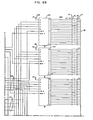
- a control microprocessor 19 directs the overall scanning of the key locations in a manner well known in the art.
- the microprocessor may be, for example, an Intel type 8048 or its equivalent, many of which have been commercially available for a number of years. Similar microprocessor based keyboard scanners exist for both capacitive and resistive circuitry and are commercially available. Hence, no great detail is indulged in at this time and the overall embodiment will only be briefly described.
- An interface plug 20 supplies 5-volt DC, an electrical ground and the data and clock input/output ports to the keyboard.
- the 5-volt DC potential is labeled 29 as it appears at numerous points within Figure 6.
- the microprocessor 19 has an internal crystal oscillator that may be trimmed or regulated with the leads 22 connected to a tank oscillator circuit 23 as schematically depicted.
- the microprocessor 19 steps continuously through a sequence of operations in which a specific drive code is applied on lines 24 to select one of the six illustrated 16 to 1 decoder selector chips 25. All that is required is that an individual port P10 through P15 be activated by the processor 19 to strobe an individual decoder selector chip 25 to determine whether any keys connected to its inputs have been actuated.
- the individual decoder selector chips may be the Texas Instrument type SN54150 16 to 1 data selectors multiplexors that are well known in the industry.
- the selection code is produced by the processor 19 as a key scan and sense code appearing at ports P20 through P23 and outputted on lines 26. Inverter amplifiers are connected in these lines to produce on lines 27 the select signals A, B, C and D that are applied in common to each of the six decoder selectors 25. However, only that decoder 25 that has its decode select on from one of the lines 24 will actually decode the lines A, B, C and D.
Landscapes
- Engineering & Computer Science (AREA)
- Theoretical Computer Science (AREA)
- Push-Button Switches (AREA)
- Portable Nailing Machines And Staplers (AREA)
Applications Claiming Priority (2)
| Application Number | Priority Date | Filing Date | Title |
|---|---|---|---|
| US06/693,638 US4689608A (en) | 1985-01-22 | 1985-01-22 | Magnetically snap actuated contact keyboard apparatus |
| US693638 | 1985-01-22 |
Publications (3)
| Publication Number | Publication Date |
|---|---|
| EP0189132A2 true EP0189132A2 (fr) | 1986-07-30 |
| EP0189132A3 EP0189132A3 (en) | 1989-03-22 |
| EP0189132B1 EP0189132B1 (fr) | 1992-05-20 |
Family
ID=24785490
Family Applications (1)
| Application Number | Title | Priority Date | Filing Date |
|---|---|---|---|
| EP86100557A Expired EP0189132B1 (fr) | 1985-01-22 | 1986-01-17 | Appareil à clavier avec contacts à action brusque magnétique |
Country Status (9)
| Country | Link |
|---|---|
| US (1) | US4689608A (fr) |
| EP (1) | EP0189132B1 (fr) |
| JP (1) | JPS61171014A (fr) |
| AR (1) | AR242528A1 (fr) |
| BR (1) | BR8600148A (fr) |
| CA (1) | CA1233893A (fr) |
| DE (1) | DE3685338D1 (fr) |
| ES (1) | ES8706985A1 (fr) |
| IN (1) | IN166023B (fr) |
Cited By (3)
| Publication number | Priority date | Publication date | Assignee | Title |
|---|---|---|---|---|
| GB2496711A (en) * | 2011-11-17 | 2013-05-22 | Darfon Electronics Corp | Keyswitch utilising magnetic attraction to return key cap |
| CN105206459A (zh) * | 2015-08-07 | 2015-12-30 | 苏州达方电子有限公司 | 按键 |
| US9343247B2 (en) | 2011-11-17 | 2016-05-17 | Darfon Electronics Corp. | Keyswitch |
Families Citing this family (8)
| Publication number | Priority date | Publication date | Assignee | Title |
|---|---|---|---|---|
| DE3722616A1 (de) * | 1987-07-09 | 1989-01-19 | Triumph Adler Ag | Tastatur fuer schreib- oder aehnliche maschinen |
| ES2048595T3 (es) * | 1990-04-30 | 1994-03-16 | Marquardt Gmbh | Teclado para escribir, sobre todo para aparatos electronicos elaboradores de datos. |
| FR2825510B1 (fr) * | 2001-06-01 | 2003-09-26 | Dav | Ensemble de microcontact de signal implantable sur un circuit conducteur |
| JP2008008955A (ja) * | 2006-06-27 | 2008-01-17 | Fujinon Corp | プロジェクタ |
| CN201348962Y (zh) * | 2006-09-25 | 2009-11-18 | 捷讯研究有限公司 | 手持无线通信设备 |
| TWI476801B (zh) | 2013-02-21 | 2015-03-11 | Darfon Electronics Corp | 按鍵及其鍵盤 |
| CN103219185B (zh) * | 2013-04-09 | 2016-01-27 | 苏州达方电子有限公司 | 按键 |
| CN104269306A (zh) * | 2014-09-24 | 2015-01-07 | 苏州达方电子有限公司 | 按键 |
Citations (5)
| Publication number | Priority date | Publication date | Assignee | Title |
|---|---|---|---|---|
| US3300703A (en) * | 1963-06-04 | 1967-01-24 | Yardney International Corp | Pressure switch and apparatus incorporating same |
| GB2029105A (en) * | 1978-08-01 | 1980-03-12 | Standard Telephones Cables Ltd | Electric contact array for telephone keypad |
| EP0035189A1 (fr) * | 1980-02-27 | 1981-09-09 | LA TELEPHONIE INDUSTRIELLE ET COMMERCIALE TELIC ALCATEL S.A. dite: | Bouton-poussoir pour clavier de commande et procédé de fabrication d'un tel bouton-poussoir |
| GB2088131A (en) * | 1980-11-21 | 1982-06-03 | Keyboard The Co | Keyboard switch actuators |
| DE3119227A1 (de) * | 1981-05-14 | 1982-12-02 | Olympia Werke Ag, 2940 Wilhelmshaven | Schnappschalter mit einem permanentmagneten |
Family Cites Families (2)
| Publication number | Priority date | Publication date | Assignee | Title |
|---|---|---|---|---|
| FR1342793A (fr) * | 1962-08-04 | 1963-11-15 | Crouzet Sa | Perfectionnements aux mécanismes pour interrupteurs à action brusque |
| JPS59186214A (ja) * | 1983-04-08 | 1984-10-23 | 富士通株式会社 | 押釦スイツチ |
-
1985
- 1985-01-22 US US06/693,638 patent/US4689608A/en not_active Expired - Fee Related
- 1985-06-11 CA CA000483704A patent/CA1233893A/fr not_active Expired
- 1985-10-15 JP JP60227941A patent/JPS61171014A/ja active Pending
- 1985-10-22 AR AR85302022A patent/AR242528A1/es active
- 1985-10-28 IN IN856/MAS/85A patent/IN166023B/en unknown
-
1986
- 1986-01-16 BR BR8600148A patent/BR8600148A/pt not_active IP Right Cessation
- 1986-01-17 DE DE8686100557T patent/DE3685338D1/de not_active Expired - Fee Related
- 1986-01-17 EP EP86100557A patent/EP0189132B1/fr not_active Expired
- 1986-01-21 ES ES551088A patent/ES8706985A1/es not_active Expired
Patent Citations (5)
| Publication number | Priority date | Publication date | Assignee | Title |
|---|---|---|---|---|
| US3300703A (en) * | 1963-06-04 | 1967-01-24 | Yardney International Corp | Pressure switch and apparatus incorporating same |
| GB2029105A (en) * | 1978-08-01 | 1980-03-12 | Standard Telephones Cables Ltd | Electric contact array for telephone keypad |
| EP0035189A1 (fr) * | 1980-02-27 | 1981-09-09 | LA TELEPHONIE INDUSTRIELLE ET COMMERCIALE TELIC ALCATEL S.A. dite: | Bouton-poussoir pour clavier de commande et procédé de fabrication d'un tel bouton-poussoir |
| GB2088131A (en) * | 1980-11-21 | 1982-06-03 | Keyboard The Co | Keyboard switch actuators |
| DE3119227A1 (de) * | 1981-05-14 | 1982-12-02 | Olympia Werke Ag, 2940 Wilhelmshaven | Schnappschalter mit einem permanentmagneten |
Non-Patent Citations (1)
| Title |
|---|
| IBM TECHNICAL DISCLOSURE BULLETIN, vol. 24, no. 8, January 1982, pages 4314-4315, New York, US; K.A. LENNON: "Spring and magnet keyboard actuator" * |
Cited By (7)
| Publication number | Priority date | Publication date | Assignee | Title |
|---|---|---|---|---|
| GB2496711A (en) * | 2011-11-17 | 2013-05-22 | Darfon Electronics Corp | Keyswitch utilising magnetic attraction to return key cap |
| TWI473134B (zh) * | 2011-11-17 | 2015-02-11 | Darfon Electronics Corp | 按鍵 |
| US9064651B2 (en) | 2011-11-17 | 2015-06-23 | Darfon Electronics Corp. | Keyswitch |
| US9099261B2 (en) | 2011-11-17 | 2015-08-04 | Darfon Electronics Corp. | Keyswitch |
| GB2496711B (en) * | 2011-11-17 | 2015-12-30 | Darfon Electronics Corp | Keyswitch |
| US9343247B2 (en) | 2011-11-17 | 2016-05-17 | Darfon Electronics Corp. | Keyswitch |
| CN105206459A (zh) * | 2015-08-07 | 2015-12-30 | 苏州达方电子有限公司 | 按键 |
Also Published As
| Publication number | Publication date |
|---|---|
| US4689608A (en) | 1987-08-25 |
| ES8706985A1 (es) | 1987-06-16 |
| BR8600148A (pt) | 1986-09-23 |
| JPS61171014A (ja) | 1986-08-01 |
| DE3685338D1 (de) | 1992-06-25 |
| EP0189132B1 (fr) | 1992-05-20 |
| ES551088A0 (es) | 1987-06-16 |
| AR242528A1 (es) | 1993-04-30 |
| IN166023B (fr) | 1990-03-03 |
| CA1233893A (fr) | 1988-03-08 |
| EP0189132A3 (en) | 1989-03-22 |
Similar Documents
| Publication | Publication Date | Title |
|---|---|---|
| US3971902A (en) | Keyboard switch assembly having one piece plural pushbutton actuator and resilient mounting structure for plural cantilever beam contacts | |
| US4059737A (en) | Keyboard | |
| US4582967A (en) | Key switch assembly | |
| US3760137A (en) | Matrix push-button switch | |
| EP0087369B2 (fr) | Clavier électronique amélioré | |
| US6392515B1 (en) | Magnetic switch with multi-wide actuator | |
| US4194097A (en) | Membrane keyboard apparatus with tactile feedback | |
| US5357104A (en) | Opto-leaf switch for pinball games having an interrupter means mounted on a leaf spring actuator arm | |
| EP1028446B1 (fr) | Commutateur combiné rotatif et à bouton-poussoir | |
| EP0189132B1 (fr) | Appareil à clavier avec contacts à action brusque magnétique | |
| EP0095585A2 (fr) | Clavier à barre de touches | |
| US3928741A (en) | Momentary contact single pole switch | |
| US3996428A (en) | Pushbutton keyboard assembly with over center diaphragm contact | |
| US4331851A (en) | Printed circuit board having data input devices mounted thereon and input devices therefor | |
| US3826882A (en) | Electric keyboards for office machines | |
| US6689977B2 (en) | Keyswitch having a keytop that is upwardly and downwardly movable and method of assembling the same | |
| US4375585A (en) | Deformable switch keyboard | |
| US5684279A (en) | Computer keyboard with improved membrane keyswitch structure having deflection concentration feature | |
| US4496803A (en) | Data entry switch | |
| CA1154000A (fr) | Clavier et mode de realisation | |
| US4314112A (en) | Keyboard having switches with tactile feedback | |
| US3928736A (en) | Keyboard switch assembly having discrete helical conductors providing wiping action | |
| US3783205A (en) | Keyboard switch matrix assembly with improved guide means for reducing transfer of bounding motion to movable conductor | |
| USRE29440E (en) | Calculator keyboard switch with disc spring contact and printed circuit board | |
| US3959611A (en) | Pushbutton keyboard system having plural level wire-like contact |
Legal Events
| Date | Code | Title | Description |
|---|---|---|---|
| PUAI | Public reference made under article 153(3) epc to a published international application that has entered the european phase |
Free format text: ORIGINAL CODE: 0009012 |
|
| AK | Designated contracting states |
Kind code of ref document: A2 Designated state(s): BE CH DE FR GB IT LI NL SE |
|
| 17P | Request for examination filed |
Effective date: 19861125 |
|
| PUAL | Search report despatched |
Free format text: ORIGINAL CODE: 0009013 |
|
| AK | Designated contracting states |
Kind code of ref document: A3 Designated state(s): BE CH DE FR GB IT LI NL SE |
|
| 17Q | First examination report despatched |
Effective date: 19900817 |
|
| RAP1 | Party data changed (applicant data changed or rights of an application transferred) |
Owner name: LEXMARK INTERNATIONAL, INC. |
|
| GRAA | (expected) grant |
Free format text: ORIGINAL CODE: 0009210 |
|
| 111Z | Information provided on other rights and legal means of execution |
Free format text: BE CH DE FR GB IT LI NL SE |
|
| AK | Designated contracting states |
Kind code of ref document: B1 Designated state(s): BE CH DE FR GB IT LI NL SE |
|
| REF | Corresponds to: |
Ref document number: 3685338 Country of ref document: DE Date of ref document: 19920625 |
|
| ET | Fr: translation filed | ||
| ITF | It: translation for a ep patent filed | ||
| PLBE | No opposition filed within time limit |
Free format text: ORIGINAL CODE: 0009261 |
|
| STAA | Information on the status of an ep patent application or granted ep patent |
Free format text: STATUS: NO OPPOSITION FILED WITHIN TIME LIMIT |
|
| 26N | No opposition filed | ||
| EAL | Se: european patent in force in sweden |
Ref document number: 86100557.7 |
|
| PGFP | Annual fee paid to national office [announced via postgrant information from national office to epo] |
Ref country code: FR Payment date: 19951213 Year of fee payment: 11 |
|
| PGFP | Annual fee paid to national office [announced via postgrant information from national office to epo] |
Ref country code: SE Payment date: 19951215 Year of fee payment: 11 |
|
| PGFP | Annual fee paid to national office [announced via postgrant information from national office to epo] |
Ref country code: NL Payment date: 19951218 Year of fee payment: 11 |
|
| PGFP | Annual fee paid to national office [announced via postgrant information from national office to epo] |
Ref country code: GB Payment date: 19951228 Year of fee payment: 11 Ref country code: DE Payment date: 19951228 Year of fee payment: 11 |
|
| PGFP | Annual fee paid to national office [announced via postgrant information from national office to epo] |
Ref country code: BE Payment date: 19951229 Year of fee payment: 11 |
|
| PGFP | Annual fee paid to national office [announced via postgrant information from national office to epo] |
Ref country code: CH Payment date: 19960123 Year of fee payment: 11 |
|
| PG25 | Lapsed in a contracting state [announced via postgrant information from national office to epo] |
Ref country code: GB Effective date: 19970117 |
|
| PG25 | Lapsed in a contracting state [announced via postgrant information from national office to epo] |
Ref country code: SE Effective date: 19970118 |
|
| PG25 | Lapsed in a contracting state [announced via postgrant information from national office to epo] |
Ref country code: LI Effective date: 19970131 Ref country code: CH Effective date: 19970131 Ref country code: BE Effective date: 19970131 |
|
| BERE | Be: lapsed |
Owner name: LEXMARK INTERNATIONAL INC. Effective date: 19970131 |
|
| PG25 | Lapsed in a contracting state [announced via postgrant information from national office to epo] |
Ref country code: NL Effective date: 19970801 |
|
| GBPC | Gb: european patent ceased through non-payment of renewal fee |
Effective date: 19970117 |
|
| REG | Reference to a national code |
Ref country code: CH Ref legal event code: PL |
|
| PG25 | Lapsed in a contracting state [announced via postgrant information from national office to epo] |
Ref country code: FR Effective date: 19970930 |
|
| NLV4 | Nl: lapsed or anulled due to non-payment of the annual fee |
Effective date: 19970801 |
|
| PG25 | Lapsed in a contracting state [announced via postgrant information from national office to epo] |
Ref country code: DE Effective date: 19971001 |
|
| EUG | Se: european patent has lapsed |
Ref document number: 86100557.7 |
|
| REG | Reference to a national code |
Ref country code: FR Ref legal event code: ST |
|
| PG25 | Lapsed in a contracting state [announced via postgrant information from national office to epo] |
Ref country code: IT Free format text: LAPSE BECAUSE OF NON-PAYMENT OF DUE FEES;WARNING: LAPSES OF ITALIAN PATENTS WITH EFFECTIVE DATE BEFORE 2007 MAY HAVE OCCURRED AT ANY TIME BEFORE 2007. THE CORRECT EFFECTIVE DATE MAY BE DIFFERENT FROM THE ONE RECORDED. Effective date: 20050117 |