EP0189009A2 - Abzugsmechanismus für einen elektromechanischen Antrieb einer Büroheftmaschine - Google Patents
Abzugsmechanismus für einen elektromechanischen Antrieb einer Büroheftmaschine Download PDFInfo
- Publication number
- EP0189009A2 EP0189009A2 EP85830299A EP85830299A EP0189009A2 EP 0189009 A2 EP0189009 A2 EP 0189009A2 EP 85830299 A EP85830299 A EP 85830299A EP 85830299 A EP85830299 A EP 85830299A EP 0189009 A2 EP0189009 A2 EP 0189009A2
- Authority
- EP
- European Patent Office
- Prior art keywords
- striker
- base
- electromechanical actuator
- trigger mechanism
- fact
- Prior art date
- Legal status (The legal status is an assumption and is not a legal conclusion. Google has not performed a legal analysis and makes no representation as to the accuracy of the status listed.)
- Granted
Links
Images


Classifications
-
- B—PERFORMING OPERATIONS; TRANSPORTING
- B25—HAND TOOLS; PORTABLE POWER-DRIVEN TOOLS; MANIPULATORS
- B25C—HAND-HELD NAILING OR STAPLING TOOLS; MANUALLY OPERATED PORTABLE STAPLING TOOLS
- B25C5/00—Manually operated portable stapling tools; Hand-held power-operated stapling tools; Staple feeding devices therefor
- B25C5/10—Driving means
- B25C5/15—Driving means operated by electric power
Definitions
- the present invention relates generally to an electromechanical actuator for operating a desk stapler, and particularly to such a device having an improved trigger mechanism.
- an electromechanical actuator device which allows automatic operation of a desk stapler of standard type to be obtained.
- This electromechanical actuator device comprises an outer casing in which a conventional manually operated desk stapler can be housed, and which has a triggering mechanism for initiating operation of a presser unit which exerts a compression on the movable part of the desk stapler to effect application of the staples.
- the trigger mechanism of this known electromechanical actuator device includes a lever which, upon introduction into the machine of the sheets to be stapled, is turned by contact with the sheets and causes the actuation of the presser unit which then operates the stapler.
- the present invention seeks therefore to provide an electromechanical actuator for a desk stapler, which can be triggered with a greater sensitivity than the hithertofore known device, and which is therefore capable of providing a secure operation and offers the possibility of always obtaining a precise positioning of the staple.
- a particular feature of the present invention is that such positioning can be made adjustable within a wide range, in dependence on any particular requirements.
- the present invention also seeks to provide a triggering mechanism for an electromechanical actuator for a stapling machine, which can readily be fitted to an actuator of the type described in our earlier Italian Patent application referred to above, thereby moreover, rendering more precise and secure the operation of the known devices as well.
- a trigger mechanism for an electromechanical actuator device for operating a desk stapler characterised by the fact that it comprises a movable assembly selectively positionable in the casing of an electromechanical actuator device the movable assembly having a pivotable striker projecting into the path of sheets introduced into the stapler to be stapled thereby, such that upon introduction of the sheets to be stapled the striker is caused to pivot into contact with the operating member of a microswitch for control of the said electromechanical actuator.
- a particular feature of the present invention is that it provides a triggering mechanism which, as well as having significantly improved operating characteristics, is structurally simple and is rapid, easy and economical to prcduce. Moreover, the trigger mechanism of the invention, as well as being easily obtainable starting from commonly commercially available materials, is highly competitive from a purely economic point of view.
- the present invention provides an electromechanical actuator device for a desk stapler of the type comprising a casing having sides in which are respective slots for allowing the introduction of sheets of paper to be stapled by a stapler housed in the casing with its operating head aligned with the slots, characterised in that the actuator has a trigger mechanism including a base adjustable longitudinally of the slots and carrying a pivotable striker which projects into the path of the sheets to be stapled so as to be contacted thereby as they are introduced, and a microswitch carried by the said base in a position such as to be contacted by the striker as it turns, the microswitch being electrically connected to the actuator so as to initiate operation thereof when switched by contact with the striker.
- a trigger mechanism including a base adjustable longitudinally of the slots and carrying a pivotable striker which projects into the path of the sheets to be stapled so as to be contacted thereby as they are introduced, and a microswitch carried by the said base in a position such as to be contacted by the striker as it
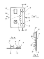
- the triggering mechanism shown is adapted for use in an electromechanical actuator for a desk stapler, and comprises a movable trigger assembly which is indicated generally with the reference numeral 1 and which can be fitted so as to be slidable as will be more clearly seen hereinbelow, between the sides 2 of the outer casing of an electromechanical actuator device such as that forming the subject of the Italian Patent Application previously referred to.
- the movable trigger assembly 1 includes a base 3, illustrated in Figures from 6 to 8, which has lateral edges 4 which slidably engage in guide grooves 5 provided on the inner surfaces of the sides 2.
- the base 3 has, adjacent its front edge, a transverse recess 6 and is provided with upstanding pins 7 for coupling of a retaining element 10 which will be described hereinbelow.
- a support block 11 flanked by a guide block 12 having a channel in its upper face.
- On the support block 11 there is fixed one end of a resilient tongue 13 the middle portion of which lies in the channel in the guide block 12 and the free end of which projects laterally through a slot 17 in one of the sides 2.
- the free end of the tongue 13 has an actuating head 14 provided with an inclined notched section 15 which engages with a correspondingly inclined notched rack 16 formed on one edge of the slot 17 in the side 2 of the casing in the region where introduction of the sheet takes place.
- the resilient tongue 13 elastically maintains the notched section 15 pressed against the rack 16 thus consequently holding the movable assembly in position and resisting displacement parallel to the rack 16.
- the notched section 15 is separated from the rack 16 thus allowing movement of the movable assembly with respect to the side of the casing 2, to allow it to be set in a desired position.
- the movable assembly 1 supports a pivotable striker generally indicated with the reference numeral 20, which has a U-shape conformation with two parallel arms 21 disposed vertically and projecting perpendicularly from the plane defined by the base 3, and a connecting section 22 which is turnably housed in the recess 6.
- the central portion 23 of the connecting section 22 is offset from the remainder thereof, in the plane defined by the two arms and towards the free ends of the arms 21. The purpose of this will be described hereinbelow.
- the striker element 20 is held on the base 3 by means of a retaining element 10 which has an elongate conformation with holes 31 for engagement with the pins 7 and, in its central part has an undercut recess 32 for receiving the central offset portion of the connecting section 22 of the U-shape striker 20.
- a microswitch 40 is fitted into the undercut recess 32 of the retaining element 10 and carried on the base 3 by means of positioning pins 41 extending from the base 3.
- the microswitch 40 has an actuating contact 42 facing towards the central portion 23 in such a way that upon pivoting of the striker 20 when contacted by sheets of paper introduced into the device electromechanical actuation of the desk stapler is triggered.
- the user can easily displace the movable assembly along the slot 17 to any desired position to determine how far the papers are introduced before operation of the stapler is triggered, thereby determining where on the sheet the staple is applied whereby to set a selected distance between the free edge of the sheet and the point cf application of the staples.
- the sheets to be stapled which are indicated 50 in Figure 5, when they strike the arms 21 of the striker 20, cause a horizontal inward pivoting of these arms, that is to day in a clockwise sense as seen in Figure 5, so that the central offset part 23 of the connecting portion 22 of the U-shape striker 20, upon turning, presses on the contact 42 of the microswitch 40, which initiates operation of the electromechanical actuator device.
- the particular arrangement used makes the trigger mechanism extremely sensitive so that only a very low pressure is needed to cause pivoting of the striker 20 thus obtaining a very precise operation of the electromechanical actuator device which effects the application of the staple, merely by touching the edge of the sheets to be stapled against the striker 20.
- the invention .achieves the objects proposed.
- the trigger mechanism described above whilst being structurally simple and of simplified assembly, is able to offer significant functional advantages which made the electromechanical actuator device for desk staplers more practical and effective.
- the striker element can be simply constituted by a bent metal wire which is mounted pivotably on the base but with only a limited range of turning movement due to the housing of the offset portion 23 of its connecting portion 22 in the undercut recess 32 formed in the striker retaining element.
Landscapes
- Engineering & Computer Science (AREA)
- Mechanical Engineering (AREA)
- Portable Nailing Machines And Staplers (AREA)
- Sheet Holders (AREA)
- Electrophotography Configuration And Component (AREA)
- Impact Printers (AREA)
Priority Applications (1)
| Application Number | Priority Date | Filing Date | Title |
|---|---|---|---|
| AT85830299T ATE54086T1 (de) | 1985-01-25 | 1985-12-06 | Abzugsmechanismus fuer einen elektromechanischen antrieb einer bueroheftmaschine. |
Applications Claiming Priority (2)
| Application Number | Priority Date | Filing Date | Title |
|---|---|---|---|
| IT1924785 | 1985-01-25 | ||
| IT19247/85A IT1184850B (it) | 1985-01-25 | 1985-01-25 | Elemento di azionamento per dispositivi elettromeccanici di automatizzazione di cucitrici da tavolo a punti metallici |
Publications (3)
| Publication Number | Publication Date |
|---|---|
| EP0189009A2 true EP0189009A2 (de) | 1986-07-30 |
| EP0189009A3 EP0189009A3 (en) | 1987-09-16 |
| EP0189009B1 EP0189009B1 (de) | 1990-06-27 |
Family
ID=11156096
Family Applications (1)
| Application Number | Title | Priority Date | Filing Date |
|---|---|---|---|
| EP85830299A Expired - Lifetime EP0189009B1 (de) | 1985-01-25 | 1985-12-06 | Abzugsmechanismus für einen elektromechanischen Antrieb einer Büroheftmaschine |
Country Status (6)
| Country | Link |
|---|---|
| EP (1) | EP0189009B1 (de) |
| JP (1) | JPS61173868A (de) |
| AT (1) | ATE54086T1 (de) |
| CA (2) | CA1262017C (de) |
| DE (1) | DE3578395D1 (de) |
| IT (1) | IT1184850B (de) |
Cited By (2)
| Publication number | Priority date | Publication date | Assignee | Title |
|---|---|---|---|---|
| EP0807499A3 (de) * | 1996-05-13 | 1998-11-18 | Riso Kagaku Corporation | Elektroheftgerät |
| EP0846533A3 (de) * | 1996-11-14 | 1998-11-25 | Riso Kagaku Corporation | Elektrischer Heftapparat |
Families Citing this family (1)
| Publication number | Priority date | Publication date | Assignee | Title |
|---|---|---|---|---|
| US20110033218A1 (en) * | 2009-08-04 | 2011-02-10 | Kabushiki Kaisha Toshiba | Stapling apparatus, finishing apparatus, and stapling method |
Family Cites Families (14)
| Publication number | Priority date | Publication date | Assignee | Title |
|---|---|---|---|---|
| US1940980A (en) * | 1932-03-18 | 1933-12-26 | Svenson Sven | Power actuator |
| US2275510A (en) * | 1940-09-06 | 1942-03-10 | Arrow Hart & Hegeman Electric | Directional operating means for electric switches |
| DE826726C (de) * | 1950-03-28 | 1952-01-03 | Alfred Gese | Sicherheitsschaltung fuer Elektro-Stapler |
| US2643307A (en) * | 1951-08-16 | 1953-06-23 | Frances E Shreve | Electric switch actuator |
| US2975424A (en) * | 1958-05-16 | 1961-03-21 | James J Oussani | Fastener device |
| DE1280212B (de) * | 1963-04-15 | 1968-10-17 | Matsushita Electric Ind Co Ltd | Elektrische Heftvorrichtung |
| US3282489A (en) * | 1965-01-12 | 1966-11-01 | Thomas Collators Inc | Portable solenoid driven stapler |
| JPS4325913Y1 (de) * | 1965-09-28 | 1968-10-29 | ||
| US3346163A (en) * | 1965-10-22 | 1967-10-10 | Fed Tool Engineering Co | Automatic electric stapler |
| US3524575A (en) * | 1967-03-30 | 1970-08-18 | Swingline Inc | Electric stapling machinne |
| US3625408A (en) * | 1969-03-25 | 1971-12-07 | Matsushita Electric Industrial Co Ltd | Electric stapler apparatus |
| US4199095A (en) * | 1977-12-15 | 1980-04-22 | Maruzen Kabushiki Kaisha | Stapling means |
| US4312468A (en) * | 1980-05-15 | 1982-01-26 | Pitney Bowes Inc. | System and apparatus for compensating for the difference between the actuation and release points of a switch |
| US4491260A (en) * | 1980-05-27 | 1985-01-01 | Jimena Carlos L | Electric stapler |
-
1985
- 1985-01-25 IT IT19247/85A patent/IT1184850B/it active
- 1985-12-06 DE DE8585830299T patent/DE3578395D1/de not_active Expired - Fee Related
- 1985-12-06 AT AT85830299T patent/ATE54086T1/de active
- 1985-12-06 EP EP85830299A patent/EP0189009B1/de not_active Expired - Lifetime
- 1985-12-31 CA CA1262017A patent/CA1262017C/en not_active Expired
- 1985-12-31 CA CA000498827A patent/CA1262017A/en not_active Expired
-
1986
- 1986-01-24 JP JP61012279A patent/JPS61173868A/ja active Pending
Cited By (2)
| Publication number | Priority date | Publication date | Assignee | Title |
|---|---|---|---|---|
| EP0807499A3 (de) * | 1996-05-13 | 1998-11-18 | Riso Kagaku Corporation | Elektroheftgerät |
| EP0846533A3 (de) * | 1996-11-14 | 1998-11-25 | Riso Kagaku Corporation | Elektrischer Heftapparat |
Also Published As
| Publication number | Publication date |
|---|---|
| CA1262017A (en) | 1989-10-03 |
| EP0189009A3 (en) | 1987-09-16 |
| EP0189009B1 (de) | 1990-06-27 |
| JPS61173868A (ja) | 1986-08-05 |
| DE3578395D1 (de) | 1990-08-02 |
| CA1262017C (en) | 1989-10-03 |
| IT1184850B (it) | 1987-10-28 |
| ATE54086T1 (de) | 1990-07-15 |
| IT8519247A0 (it) | 1985-01-25 |
Similar Documents
| Publication | Publication Date | Title |
|---|---|---|
| US7648054B2 (en) | Spring energized desktop stapler | |
| US5639007A (en) | Stapler with indicator assembly for indicating and dispensing staples of different sizes | |
| EP0828588B1 (de) | Handwerkzeug | |
| US4779785A (en) | Portable stationery device | |
| US4261098A (en) | Apparatus for clipping sheets together | |
| JP3554632B2 (ja) | 電動ステープラ | |
| EP0189009B1 (de) | Abzugsmechanismus für einen elektromechanischen Antrieb einer Büroheftmaschine | |
| US4838470A (en) | Stapler base | |
| US20080011808A1 (en) | Staple guide track | |
| US6981626B1 (en) | Stapler with a leg-cutting device | |
| US4358043A (en) | Spring-energized stapling machine | |
| TW490367B (en) | Stapler for forming staples to various sizes | |
| US3680759A (en) | Staplers | |
| US20080302853A1 (en) | Contoured base for desktop stapler | |
| US4299013A (en) | Paper clips | |
| US20090218381A1 (en) | Combined stapler and hole punch | |
| JPH0118297Y2 (de) | ||
| EP1577061B1 (de) | Elektrischer Heftapparat | |
| CN110919599B (zh) | 省力订书机 | |
| JPH06285772A (ja) | ホッチキス | |
| US7318545B1 (en) | Stapler with a staple-supporting device | |
| SU1676791A1 (ru) | Сшиватель документов | |
| KR20020078567A (ko) | 서류철용 날클립 압착장치 | |
| GB2072565A (en) | An improved spring-energised strapling machine | |
| JPH0955139A (ja) | 操作レバー付押釦スイッチ |
Legal Events
| Date | Code | Title | Description |
|---|---|---|---|
| PUAI | Public reference made under article 153(3) epc to a published international application that has entered the european phase |
Free format text: ORIGINAL CODE: 0009012 |
|
| AK | Designated contracting states |
Kind code of ref document: A2 Designated state(s): AT BE CH DE FR GB LI NL SE |
|
| PUAL | Search report despatched |
Free format text: ORIGINAL CODE: 0009013 |
|
| AK | Designated contracting states |
Kind code of ref document: A3 Designated state(s): AT BE CH DE FR GB LI NL SE |
|
| 17P | Request for examination filed |
Effective date: 19880212 |
|
| 17Q | First examination report despatched |
Effective date: 19890613 |
|
| GRAA | (expected) grant |
Free format text: ORIGINAL CODE: 0009210 |
|
| AK | Designated contracting states |
Kind code of ref document: B1 Designated state(s): AT BE CH DE FR GB LI NL SE |
|
| PG25 | Lapsed in a contracting state [announced via postgrant information from national office to epo] |
Ref country code: NL Effective date: 19900627 Ref country code: LI Effective date: 19900627 Ref country code: CH Effective date: 19900627 Ref country code: BE Effective date: 19900627 Ref country code: AT Effective date: 19900627 |
|
| REF | Corresponds to: |
Ref document number: 54086 Country of ref document: AT Date of ref document: 19900715 Kind code of ref document: T |
|
| REF | Corresponds to: |
Ref document number: 3578395 Country of ref document: DE Date of ref document: 19900802 |
|
| REG | Reference to a national code |
Ref country code: CH Ref legal event code: PL |
|
| ET | Fr: translation filed | ||
| NLV1 | Nl: lapsed or annulled due to failure to fulfill the requirements of art. 29p and 29m of the patents act | ||
| PLBE | No opposition filed within time limit |
Free format text: ORIGINAL CODE: 0009261 |
|
| STAA | Information on the status of an ep patent application or granted ep patent |
Free format text: STATUS: NO OPPOSITION FILED WITHIN TIME LIMIT |
|
| 26N | No opposition filed | ||
| PGFP | Annual fee paid to national office [announced via postgrant information from national office to epo] |
Ref country code: GB Payment date: 19921124 Year of fee payment: 8 |
|
| PGFP | Annual fee paid to national office [announced via postgrant information from national office to epo] |
Ref country code: SE Payment date: 19921217 Year of fee payment: 8 |
|
| PGFP | Annual fee paid to national office [announced via postgrant information from national office to epo] |
Ref country code: FR Payment date: 19921229 Year of fee payment: 8 |
|
| PGFP | Annual fee paid to national office [announced via postgrant information from national office to epo] |
Ref country code: DE Payment date: 19930114 Year of fee payment: 8 |
|
| PG25 | Lapsed in a contracting state [announced via postgrant information from national office to epo] |
Ref country code: GB Effective date: 19931206 |
|
| PG25 | Lapsed in a contracting state [announced via postgrant information from national office to epo] |
Ref country code: SE Effective date: 19931207 |
|
| GBPC | Gb: european patent ceased through non-payment of renewal fee |
Effective date: 19931206 |
|
| PG25 | Lapsed in a contracting state [announced via postgrant information from national office to epo] |
Ref country code: FR Effective date: 19940831 |
|
| PG25 | Lapsed in a contracting state [announced via postgrant information from national office to epo] |
Ref country code: DE Effective date: 19940901 |
|
| REG | Reference to a national code |
Ref country code: FR Ref legal event code: ST |
|
| EUG | Se: european patent has lapsed |
Ref document number: 85830299.5 Effective date: 19940710 |