EP0188970B1 - Betätigungsvorrichtung, anwendbar in einer Flüssigkeit unter Hochdruck - Google Patents
Betätigungsvorrichtung, anwendbar in einer Flüssigkeit unter Hochdruck Download PDFInfo
- Publication number
- EP0188970B1 EP0188970B1 EP85402623A EP85402623A EP0188970B1 EP 0188970 B1 EP0188970 B1 EP 0188970B1 EP 85402623 A EP85402623 A EP 85402623A EP 85402623 A EP85402623 A EP 85402623A EP 0188970 B1 EP0188970 B1 EP 0188970B1
- Authority
- EP
- European Patent Office
- Prior art keywords
- frame
- plunger
- fluid
- actuator according
- electromagnet
- Prior art date
- Legal status (The legal status is an assumption and is not a legal conclusion. Google has not performed a legal analysis and makes no representation as to the accuracy of the status listed.)
- Expired
Links
- 239000012530 fluid Substances 0.000 title claims description 34
- 230000000694 effects Effects 0.000 claims description 11
- 230000005415 magnetization Effects 0.000 claims description 6
- 238000005192 partition Methods 0.000 claims description 2
- 238000006073 displacement reaction Methods 0.000 description 2
- 239000013535 sea water Substances 0.000 description 2
- 230000003321 amplification Effects 0.000 description 1
- 230000007797 corrosion Effects 0.000 description 1
- 238000005260 corrosion Methods 0.000 description 1
- 238000007654 immersion Methods 0.000 description 1
- 239000007788 liquid Substances 0.000 description 1
- 239000000463 material Substances 0.000 description 1
- 238000003199 nucleic acid amplification method Methods 0.000 description 1
- 230000000717 retained effect Effects 0.000 description 1
- 239000007787 solid Substances 0.000 description 1
- 239000000725 suspension Substances 0.000 description 1
Images


Classifications
-
- B—PERFORMING OPERATIONS; TRANSPORTING
- B63—SHIPS OR OTHER WATERBORNE VESSELS; RELATED EQUIPMENT
- B63C—LAUNCHING, HAULING-OUT, OR DRY-DOCKING OF VESSELS; LIFE-SAVING IN WATER; EQUIPMENT FOR DWELLING OR WORKING UNDER WATER; MEANS FOR SALVAGING OR SEARCHING FOR UNDERWATER OBJECTS
- B63C11/00—Equipment for dwelling or working underwater; Means for searching for underwater objects
- B63C11/52—Tools specially adapted for working underwater, not otherwise provided for
-
- B—PERFORMING OPERATIONS; TRANSPORTING
- B63—SHIPS OR OTHER WATERBORNE VESSELS; RELATED EQUIPMENT
- B63G—OFFENSIVE OR DEFENSIVE ARRANGEMENTS ON VESSELS; MINE-LAYING; MINE-SWEEPING; SUBMARINES; AIRCRAFT CARRIERS
- B63G8/00—Underwater vessels, e.g. submarines; Equipment specially adapted therefor
- B63G8/14—Control of attitude or depth
- B63G8/24—Automatic depth adjustment; Safety equipment for increasing buoyancy, e.g. detachable ballast, floating bodies
-
- Y—GENERAL TAGGING OF NEW TECHNOLOGICAL DEVELOPMENTS; GENERAL TAGGING OF CROSS-SECTIONAL TECHNOLOGIES SPANNING OVER SEVERAL SECTIONS OF THE IPC; TECHNICAL SUBJECTS COVERED BY FORMER USPC CROSS-REFERENCE ART COLLECTIONS [XRACs] AND DIGESTS
- Y10—TECHNICAL SUBJECTS COVERED BY FORMER USPC
- Y10T—TECHNICAL SUBJECTS COVERED BY FORMER US CLASSIFICATION
- Y10T74/00—Machine element or mechanism
- Y10T74/11—Tripping mechanism
Definitions
- the present invention relates to an actuating device of the pusher type usable in a fluid under high pressure, for example on board an underwater vehicle capable of working at great depth.
- the object of the present invention is precisely to remedy these drawbacks by proposing a device which can operate independently of the pressure, the corrosive action and the turbidity of the ambient medium by using the linear displacement of a piston, this displacement being effected with very high reliability and requiring little energy.
- the actuating device object of the invention is defined in claim 1, and comprises, in a conventional manner, a pusher movable relative to a structure and connected to it by elastic means, for example a spring, as well as means for locking the pusher relative to this structure.
- elastic means for example a spring
- at least part of the pusher, said elastic means and the locking means are inside a frame containing a second fluid and the device comprises means allowing the pressure of the fluid contained in the frame to constantly adapt to that of the external fluid.
- first fluid will be used in the remainder of this text to designate the fluid in which the entire device works and “second fluid” to designate the fluid which is inside the built.
- the frame at least one partition pierced with a conduit allowing the passage of the second fluid. Indeed, it moves inside the frame when the device is put into operation and the diameter of the duct (s) is calculated according to the force which must be exerted by the pusher during the operation of the device.
- the locking piece can be either a rocker movable in rotation about a fixed axis relative to the frame or a free rocker or even be constituted by a set of movable balls inside a housing provided in the frame.
- the electromagnet creates a magnetic field, and therefore only attracts the plunger, when it is traversed by an electric current.
- the electromagnet comprises a coil with permanent magnetization, this magnetization being canceled by the passage of a current in the coil: thus, in this version, the plunger is only attracted by the electromagnet when the supply circuit is open.
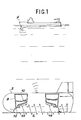
- an underwater vehicle 2 for example a nodule pickup machine, which moves on the seabed while being either remote controlled from a ship 4 or autonomous .
- Egin 2 is moved using Archechedes screws 6 and may include one or more tanks such as 8 containing a ballast 10.
- ballast 10 it may be necessary to release the ballast 10 so that machine 2 rises to the surface. This can be done for example by opening a door or a hatch 12 using an actuating device 14 such as that which is the subject of the invention.
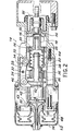
- This device appears better on the detailed sectional view of Figure 2.
- this device consists of a sealed frame 16 inside which can move a pusher 18.
- the frame 16 is filled with a fluid called "Second fluid" as opposed to the first fluid which is the one in which the machine is immersed.
- the rear part 20 of the pusher 18 is hollow and contains a spring 22, one end of which is fixed to the pusher 18 while its other end is fixed to a part 24 integral with the frame 16.
- a flexible skirt 26, the rote of which will be explained later is fixed in a sealed manner, on the one hand to the front part of the pusher 18 and on the other hand to the frame 16.
- FIG. 2 illustrates the locking position in which the pusher 18 is held using a rocker 28 which can pivot about an axis 30 fixed relative to the frame 16.
- the rocker 28 carries at one of its ends a rounded part 32 which, in the locking position illustrated in FIG. 2, is in contact with a flange 34 provided on the rear part 20 of the pusher 18 and thus prevents any movement of the latter.
- the spring 22 is in the compressed state.
- a plunger 36 also movable inside the frame 16.
- This plunger 36 consists of a body 38 and a head 40 which can come into contact with an electromagnet 42.
- the latter is connected to a supply device (not shown) by a set of wires contained in a cable 43.
- a spring 44 has one of its ends fixed to the body 38 of the plunger 36 and the other end fixed to the part 24 integral with the frame 16. It can be seen in FIG. 2 that the head 40 of the plunger 36 has dimensions such that, when it is in contact with the electromagnet 42, it abuts against a rounded part 36 provided at the end of the rocker 28 opposite the rounded part 32, which prevents any pivoting of the rocker in the anticlockwise direction seen in FIG. 2 and keeps the pusher 18 in the locked position.
- the electromagnet 42 is permanently excited and therefore attracts the head 40 of the plunger 36, which causes the rocker 28 and the pusher 18 are held in the locking position.
- we cut the power to the electromagnet 42 which therefore ceases to attract the plunger 36.
- the spring 44 Under the effect of the spring 44, it is pushed to the right of Figure 2 and arrives in the position illustrated in FIG. 3.
- the rounded part 46 of the rocker 28 is no longer maintained and the latter can pivot around the axis 30. This pivoting has the effect of lifting the rounded part 32 which is no longer in contact with the abutment face 34 of the pusher 18.
- conduits 56 which act as dash-pots, the diameter of which has been determined in order to control the speed of the second fluid when the device is put into operation, that is to say when the skirt 26 is deployed and the sleeves 48 are crushed: it is thus possible to control the force with which the pusher 18 acts on the elements which it has to move.
- the arming can be carried out using a device incorporated into the device.
- FIG. 4 illustrates one of these devices.
- a screw-nut system is used to return the pusher 18 to the locked position once the system has operated.
- This device consists of a micromotor 58, fixed relative to the frame 16, and controlling a threaded rod 60 movable in rotation and immobilized in translation.
- a nut 62 immobilized in rotation but free in translation, can move along the rod 60.
- the nut 62 carries a rocker 64 movable in rotation about an axis 66 carried by this nut 62, the rocker 64 being stressed towards the rod 60 by a spring 75.
- the rocker 64 also carries a pawl 68 movable in rotation about an axis 70 carried by the rocker, the pawl 68 being able to come into contact with a pawl stop 72. It should be noted that the pawl 68 is free, its stroke being limited by the stop 72.
- the rocker 64 In its starting position, the rocker 64 is located in the vicinity of the micromotor 58 and is in the raised position thanks to a stop 74 controlled by the motor. When the pusher 18 has operated, it is in position 18a (FIGS. 3 and 4), that is to say on the right side of FIG. 4. When it is desired to return it to the locking position, it is started.
- the motor 58 which has the effect on the one hand of erasing the stop 74 and of bringing the rocker 64 in a horizontal position, and on the other hand of rotating the rod 60.
- the nut 62 therefore moves towards the right of the figure to position 62a shown schematically in phantom.
- the pawl 68 meets the external face of the rear part 20 of the pusher 18, it switches anticlockwise as seen in FIG. 4, then returns to its normal position when it is located opposite an orifice 76 provided in part 20 of the pusher 18.
- the pawl 68 is then in contact with one of the faces of this orifice and the motor 58 is started so as to bring the pusher 18 back from position 18a in the locked position.
- FIG. 5 illustrates a variant in which the rocker 28 of FIG. 2 is replaced by a set of balls 80 movable inside a housing 82.
- the end balls 84 and 86 play the same role as the rounded parts 32 and 46 of rocker 28 respectively.
- the balls 80 can either be embedded in a flexible material such as rubber, or are free to move inside the housing 82.
- the pivoting rocker 28 of FIG. 2 is replaced by a free rocker 90, which comprises at its two ends rounded parts 92 and 94 which play the same role as the rounded parts 32 and 46 of the rocker 28 of Figure 2.
- the rocker 90 is a free rocker, that is to say that it is not mounted on a fixed axis like the rocker 28 but can move freely inside its housing when the device is started.
- the stroke of the pusher 18 and the plunger 36 and the shape of the housing of the rocker 90 are determined so that it does not escape.
- the device which is the subject of the invention has interesting advantages since it is simple to produce and of safe and reliable operation.
- it involves a limited mechanical action determined by the calibration of the springs 22 and 44 and by the diameter of the conduits such as 56.
- the fact that the entire mechanism is located inside d A sealed frame filled with fluid avoids all the problems due to corrosion and turbidity of the ambient environment.
- the presence of the skirt 20 and the sleeves 48 means that the interior space of the frame 16 is permanently completely filled with a fluid, the pressure of which automatically adjusts to that of the surrounding medium. It is thus possible to work at any depth, that is to say either close to the surface with low pressure, or in the deep seabed (of the order of 11,000 meters for the largest ocean trenches) where the pressure is very high.
- the invention is not limited to the single embodiment which has just been described, but that it is possible to envisage variants without thereby departing from the scope of the invention.
- the operation of the device has been described in the case where the electromagnet is permanently energized, the interruption of the supply causing the plunger 36 to detach from the electromagnet 42.
- the electromagnet comprises a coil which attracts the head 40 of the plunger 36 thanks to its permanent magnetization, this magnetization being canceled when the coil is energized.
Landscapes
- Engineering & Computer Science (AREA)
- Mechanical Engineering (AREA)
- Ocean & Marine Engineering (AREA)
- Aviation & Aerospace Engineering (AREA)
- Actuator (AREA)
- Electromagnets (AREA)
Claims (10)
Applications Claiming Priority (2)
| Application Number | Priority Date | Filing Date | Title |
|---|---|---|---|
| FR8500038 | 1985-01-03 | ||
| FR8500038A FR2575524B1 (fr) | 1985-01-03 | 1985-01-03 | Dispositif d'actionnement utilisable dans un fluide sous haute pression |
Publications (2)
| Publication Number | Publication Date |
|---|---|
| EP0188970A1 EP0188970A1 (de) | 1986-07-30 |
| EP0188970B1 true EP0188970B1 (de) | 1988-10-26 |
Family
ID=9314981
Family Applications (1)
| Application Number | Title | Priority Date | Filing Date |
|---|---|---|---|
| EP85402623A Expired EP0188970B1 (de) | 1985-01-03 | 1985-12-24 | Betätigungsvorrichtung, anwendbar in einer Flüssigkeit unter Hochdruck |
Country Status (6)
| Country | Link |
|---|---|
| US (1) | US4706596A (de) |
| EP (1) | EP0188970B1 (de) |
| JP (1) | JPS61161703A (de) |
| CA (1) | CA1253190A (de) |
| DE (1) | DE3565812D1 (de) |
| FR (1) | FR2575524B1 (de) |
Families Citing this family (4)
| Publication number | Priority date | Publication date | Assignee | Title |
|---|---|---|---|---|
| US4951587A (en) * | 1989-08-09 | 1990-08-28 | Honeywell Inc. | Recovery system for a training torpedo |
| US5280761A (en) * | 1992-08-17 | 1994-01-25 | The United States Of America As Represented By The Secretary Of The Navy | Combined bulbous bow and sonar dome for a vessel |
| US6722216B2 (en) * | 2001-07-17 | 2004-04-20 | Ansul Incorporated | Booster actuator |
| WO2024194787A1 (en) * | 2023-03-21 | 2024-09-26 | Tyco Fire Products Lp | High force booster actuator |
Family Cites Families (8)
| Publication number | Priority date | Publication date | Assignee | Title |
|---|---|---|---|---|
| US2361949A (en) * | 1942-01-20 | 1944-11-07 | Jesse D Langdon | Torpedo carrier and discharger |
| US2778226A (en) * | 1954-08-04 | 1957-01-22 | Mclean Dev Lab Inc | Electromagnetic trip |
| US3006196A (en) * | 1960-01-18 | 1961-10-31 | Basic Products Corp | Controller for machines |
| US3552419A (en) * | 1969-05-06 | 1971-01-05 | Clement Walker Weston Jr | Deep submersible power assembly |
| DE2063059A1 (de) * | 1970-12-22 | 1972-07-13 | Babcock & Wilcox Ag | Betätigungsvorrichtung an Unter wassergeraten |
| US4187796A (en) * | 1975-06-27 | 1980-02-12 | The United States Of America As Represented By The Secretary Of The Navy | Specific gravity equalizer system |
| US4416313A (en) * | 1981-10-30 | 1983-11-22 | Armatron International, Inc. | Double acting log splitter |
| US4405263A (en) * | 1981-12-14 | 1983-09-20 | Armco Inc. | Underwater devices with remotely operated latch means |
-
1985
- 1985-01-03 FR FR8500038A patent/FR2575524B1/fr not_active Expired
- 1985-12-19 US US06/811,005 patent/US4706596A/en not_active Expired - Fee Related
- 1985-12-20 CA CA000498330A patent/CA1253190A/en not_active Expired
- 1985-12-24 EP EP85402623A patent/EP0188970B1/de not_active Expired
- 1985-12-24 DE DE8585402623T patent/DE3565812D1/de not_active Expired
- 1985-12-26 JP JP60292356A patent/JPS61161703A/ja active Pending
Also Published As
| Publication number | Publication date |
|---|---|
| FR2575524A1 (fr) | 1986-07-04 |
| US4706596A (en) | 1987-11-17 |
| CA1253190A (en) | 1989-04-25 |
| JPS61161703A (ja) | 1986-07-22 |
| EP0188970A1 (de) | 1986-07-30 |
| FR2575524B1 (fr) | 1987-01-30 |
| DE3565812D1 (en) | 1988-12-01 |
Similar Documents
| Publication | Publication Date | Title |
|---|---|---|
| EP1571080A1 (de) | Aufhängevorrichtung eines Flugzeugtriebwerks an einem Flügelpylon | |
| CH652462A5 (fr) | Actuateur lineaire a moteur electrique. | |
| EP0188970B1 (de) | Betätigungsvorrichtung, anwendbar in einer Flüssigkeit unter Hochdruck | |
| CA1292030C (fr) | Dispositif de stockage d'energie mecanique a force d'accrochage nulle | |
| EP0089882B1 (de) | Abnehmbare Einrichtung zur Verriegelung eines Schaltschuetzes in seiner aktiven Stellung | |
| EP1110789A1 (de) | Kraftstofftankventil und damit ausgerüsteter Tank | |
| EP0837957B1 (de) | Platinenwahlvorrichtung für die schaftmaschine einer webmaschine | |
| FR2494030A1 (fr) | Dispositifs de commutation electrique | |
| EP1709655B1 (de) | Bistabile betätigungsvorrichtung einer bewegbaren, nicht durchgehenden, welle und damit versehener schalter für batterie | |
| FR2872184A1 (fr) | Chasse d'eau automatique a ventouse magnetique | |
| FR2583520A1 (fr) | Detecteur de vitesse de vehicule automobile | |
| FR2720806A1 (fr) | Dispositif de freinage d'un arbre rotatif, moteur et appareillage comprenant un tel dispositif. | |
| FR2511538A1 (fr) | Selecteur de mode pour appareil de lecture-enregistrement tel qu'un magnetoscope | |
| FR3097286A1 (fr) | Dispositif de verrouillage d'un objet le long d'un cáble | |
| EP0378934A1 (de) | Mechanismus zur Erzielung einer Translationsbewegung in einer Unterwasserumgebung und Sonargerät, ausgestattet mit einem solchen Mechanismus | |
| EP3524860B1 (de) | Steuervorrichtung | |
| FR3058773A1 (fr) | Dispositif de lubrification sous vide pour volant d’inertie | |
| EP1132581A1 (de) | Elektromagnetventil mit Pneumatikfeder und Kniehebelmechanismus | |
| CA2868412C (fr) | Dispositif actionneur a commande electrique integrant une fonction thermostatique, vanne. | |
| FR2591182A1 (fr) | Dispositif de commande d'un objet submerge remorque. | |
| EP3793894B1 (de) | Frischluftzufuhrsystem für ein unterseeboot und unterseeboot mit einem solchen system | |
| EP1565678B1 (de) | Schiebersteuerventil | |
| EP1845546A2 (de) | Bistabile Stellvorrichtung einer beweglichen Welle und Batteriestromunterbrecher mit einer solchen Vorrichtung | |
| FR2773908A1 (fr) | Actionneur electromagnetique multi-stable et vehicule automobile equipe de cet actionneur | |
| FR2900204A1 (fr) | Generateur d'energie mecanique a partir de l'acceleration centripete de la poussee d'archimede appliquee a un systeme de flotteur |
Legal Events
| Date | Code | Title | Description |
|---|---|---|---|
| PUAI | Public reference made under article 153(3) epc to a published international application that has entered the european phase |
Free format text: ORIGINAL CODE: 0009012 |
|
| AK | Designated contracting states |
Kind code of ref document: A1 Designated state(s): DE GB SE |
|
| 17P | Request for examination filed |
Effective date: 19870107 |
|
| RAP1 | Party data changed (applicant data changed or rights of an application transferred) |
Owner name: COMMISSARIAT A L'ENERGIE ATOMIQUE |
|
| 17Q | First examination report despatched |
Effective date: 19871214 |
|
| GRAA | (expected) grant |
Free format text: ORIGINAL CODE: 0009210 |
|
| AK | Designated contracting states |
Kind code of ref document: B1 Designated state(s): DE GB SE |
|
| GBT | Gb: translation of ep patent filed (gb section 77(6)(a)/1977) | ||
| REF | Corresponds to: |
Ref document number: 3565812 Country of ref document: DE Date of ref document: 19881201 |
|
| PLBE | No opposition filed within time limit |
Free format text: ORIGINAL CODE: 0009261 |
|
| STAA | Information on the status of an ep patent application or granted ep patent |
Free format text: STATUS: NO OPPOSITION FILED WITHIN TIME LIMIT |
|
| 26N | No opposition filed | ||
| PGFP | Annual fee paid to national office [announced via postgrant information from national office to epo] |
Ref country code: DE Payment date: 19911122 Year of fee payment: 7 |
|
| PGFP | Annual fee paid to national office [announced via postgrant information from national office to epo] |
Ref country code: SE Payment date: 19911125 Year of fee payment: 7 |
|
| PGFP | Annual fee paid to national office [announced via postgrant information from national office to epo] |
Ref country code: GB Payment date: 19911219 Year of fee payment: 7 |
|
| PG25 | Lapsed in a contracting state [announced via postgrant information from national office to epo] |
Ref country code: GB Effective date: 19921224 |
|
| PG25 | Lapsed in a contracting state [announced via postgrant information from national office to epo] |
Ref country code: SE Effective date: 19921225 |
|
| GBPC | Gb: european patent ceased through non-payment of renewal fee |
Effective date: 19921224 |
|
| PG25 | Lapsed in a contracting state [announced via postgrant information from national office to epo] |
Ref country code: DE Effective date: 19930901 |
|
| EUG | Se: european patent has lapsed |
Ref document number: 85402623.4 Effective date: 19930709 |