EP0188732A2 - Headrest - Google Patents
Headrest Download PDFInfo
- Publication number
- EP0188732A2 EP0188732A2 EP85115822A EP85115822A EP0188732A2 EP 0188732 A2 EP0188732 A2 EP 0188732A2 EP 85115822 A EP85115822 A EP 85115822A EP 85115822 A EP85115822 A EP 85115822A EP 0188732 A2 EP0188732 A2 EP 0188732A2
- Authority
- EP
- European Patent Office
- Prior art keywords
- headrest
- sector
- support
- headrest body
- support stay
- Prior art date
- Legal status (The legal status is an assumption and is not a legal conclusion. Google has not performed a legal analysis and makes no representation as to the accuracy of the status listed.)
- Granted
Links
Images



Classifications
-
- B—PERFORMING OPERATIONS; TRANSPORTING
- B60—VEHICLES IN GENERAL
- B60N—SEATS SPECIALLY ADAPTED FOR VEHICLES; VEHICLE PASSENGER ACCOMMODATION NOT OTHERWISE PROVIDED FOR
- B60N2/00—Seats specially adapted for vehicles; Arrangement or mounting of seats in vehicles
- B60N2/80—Head-rests
- B60N2/806—Head-rests movable or adjustable
- B60N2/838—Tiltable
- B60N2/841—Tiltable characterised by their locking devices
- B60N2/847—Tiltable characterised by their locking devices with stepwise positioning
-
- B—PERFORMING OPERATIONS; TRANSPORTING
- B60—VEHICLES IN GENERAL
- B60N—SEATS SPECIALLY ADAPTED FOR VEHICLES; VEHICLE PASSENGER ACCOMMODATION NOT OTHERWISE PROVIDED FOR
- B60N2/00—Seats specially adapted for vehicles; Arrangement or mounting of seats in vehicles
- B60N2/80—Head-rests
- B60N2/806—Head-rests movable or adjustable
- B60N2/865—Head-rests movable or adjustable providing a fore-and-aft movement with respect to the occupant's head
Definitions
- the present invention relates to a headrest wherein the headrest can be moved forward and backward in relation to a support stay to adjust its position.
- FIG. 1 One of the headrest of the latter type is shown in Fig. 1, which is intended to adjust its position by controlling its inclination and includes a locking device for preventing return action.
- numeral 1 denotes a support means which is mounted on one end of a support stay 2. The other end of the support stay 2 is inserted in a hole provided at the upper portion of a seat back 3 and fixed thereto.
- the support means 1 is rotatablly provided with a headrest frame or movable member 5 through a pivot shaft 4 so as to incline a headrest body 20 about the pivot shaft 4.
- Movable member 5 is provided with a member 6 which has a plurality of teeth 7 continuously formed along an arc the center of which is the same as that of said pivot shaft 4, land section 8 provided at one end of said teeth 7, and stopper portion 9 disposed at the end of said land section 8.
- Support member 1 pivotally supports a pawl means 11 through a pin 10 which can be engaged with one of said teeth 7 selectively.
- Said teeth 7 and paw means 11 construct a device for locking the returning movement of a headrest body 20 in relation to the support stay 2. Further, the support member 1 pivotally supports a hook 13 which can be engaged with a hanger portion 14 provided at the end of the pawl means 11 for holding said pawl means 11 in the condition of being released from the teeth 7.
- the pawl means 11 is operatively connected with the hook 13 through a coil spring 15 which acts for rotating both of said means 11 and 13 in anti-clockwise direction (shown by an arrow in Fig. 1) respectively.
- the pawl means 11 can be engaged with one of the teeth by the action of said coil spring 15.
- the hook 13 is biased by the coil spring 15 so as to be engaged with the pawl means 11, wherein said hook 13 is engaged with the hanger portion 14 when the pawl means 11 moves in relation to the teeth 7 and reaches on the land section 8.
- a projecting wall 16 is provided at the position corresponding to the hook 13.
- Said projecting wall 16 collides with the hook 13 and acts to release the engagement between the pawl means 11 and hook 13 against the function of the coil spring 15 when said pawl means 11 is engaged with the tooth 7 arranged at left end as shown in Fig. 1.
- support means 1 and movable member 5 are operatively connected with each other through a coil spring 17.
- Said coil spring 17 functions so as to rotate the movable member 5 about the pivot shaft 4 in clock-wise directionin Fig. 1.
- the headrest body 20 rotatablly mounted on the suppot stay 2 is inclined forward and beckward so as to adjust the front and rear positions thereof. Therefore, a sufficient stroke for moving the headrest forward and beckward cannot be obtained, and most of the passengers cannot be satisfied. And, the mechanism for controlling the rotation and return movement of the headrest is somewhat too complicated, thereby making the cost high and its durability doubtful.
- the present invention is therefore intended to eliminate the above-mentioned drawbacks.
- a first object of the present invention is to provide a headrest which can be moved forward and backward, without using any projected means such as the knob, to adjust its position.
- a second object of the present invention is to provide a headrest whose position can be adjusted only by grasping its head portion by a hand and forcing it forward and backward.
- a third object of the present invention is to provide a headrest in which a position adjusting mechanism, simple in construction and easy to assemble, is incorporated.
- a pair of link members are swingably attached to the upper end of a support stay planted in the seat back, while a base frame is fixedly arranged in the hollow body of a headrest and the front end of each of the paired swingable link members is pivoted on the base frame, so that a link mechanism can be formed as a swingable support means fo enabling the headrest to be moved forward and backward.
- a lock mechanism for allowing the swingable support means to be freely swung, corresponding to the movement (or forward movement, for example) of the headrest body in one direction, and limiting the swinging movement of the swingable support means against the movement of the headrest body in another direction.
- the headrest body can be grasped by a hand and moved form the start end of its moving stroke to the stop end thereof by the action of the link mechanism.
- the engaging relation between the teeth of the sector and the click of the click member is changed and when it is released from the hand at a desired position, the click of the click member is engaged with that tooth of the sector which corresponds to the desired position, thereby stopping it from returning in its start end direction.
- the click member is released from any of the .teeth of the sector, leaving it released.
- the click of the click member is engaged with one of the teeth of the sector, thereby keeping it under initial state.
- the headrest body 20 comprises covering a headrest frame 2 1 with pad or the like and both of the headrest body 20 and frame 21 are supported, movable forward and backward, on the support stay 18 through the support bracket 1 9 and link mechanism 30.
- the link mechanism 30 comprises the support bracket 19 a first swing link member 40 whose base is pivoted on the front portion of the support bracket 19 through a pivot shaft 31, a second swing link member 50 whose base is pivoted on the back portion of the support bracket 19 through a pivot shaft 32, and a bracket 22 fixed to the headrest frame 21 and on which the front ends of the first and second swing link members 4 0 and 50 erected in parallel from the support bracket 19 are pivoted through pivot shafts 33 and 34, respectively.
- the link mechanism 30 is called parallel link mechanism, but it is not necessarily needed that the first and second swing link members 40 and 50 are arranged like this.
- the headrest body 20 is urged in right direction in Fig. 1 by means of a spring (not shown).
- a sector 41 is located at the base of the first swing link member 40 and teeth 42 are formed on one side of the sector 41, taking the pivot shaft 31 as their center.
- a click member 60 Pivoted on the support bracket 19 which supports the first swing link member 40 through the pivot shaft 31, is a click member 60 through the pivot shaft 32.
- These sector 41 and click member 60 form a lock mechanism.
- the click member 60 has a click 61 which can get over the teeth 42 of the sector 41 not in a direction but in the reverse direction thereof.
- the click 61 is urged by a spring 62 to engage the teeth 42 of the sector 41.
- the sector 41 has a pushing portion 43 continuous from its last tooth and contacted with the click 61 of the click member 60 to release the click 61 from the teeth 42 of the sector 41 when the headrest body 20 is moved to the stop end of its moving stroke.
- the pushing portion 43 of the sector 41 serves as a release member for swinging the click member 60 to release the click 61 from the teeth 42 of the sector 41.
- a pole member 70 is pivoted on the second swing link member 50 through the pivot shaft 34 and serves as a holder means for holding the click 61 of the click member 60 released from the teeth 42 of the sector 41 when the headrest body 20 is moved to the stop end of its moving stroke.
- the release member and holder means form a lock release mechanism.
- the pole member 70 has an engaging end 71 engageable with an engaged end 63 of the click member 60 and urged by a spring 72 in clockwise direction in which a stopper 73 is contacted with a part of the second swing link member 50.
- the engaging end 71 has a side 74 engaged with and released from the end 63 of the click member 60.
- a returning means 23 is erected on the bracket 22 fixed to the headrest frame 21 and saves to engage the side 74 to release the pole member 70 when the headrest body 20 which has released at the stop end of its moving stroke is returned to the start end or its initial position.
- the headrest body 20 and frame 21 are at the start end of their moving stroke, and the click 61 of the click member 60 is engaged with the start end of the teeth 42 of the sector 41 to prevent both of the headrest frame 21 and body 20 from moving in right direction in Fig. 3.
- the headrest body and frame are stopped like this whichever teeth of the sector 41 the click 61 may be engaged with.
- the headrest body 20 is grasped by a hand and force is applied to the headrest body 20 to move it in left direction in Fig. 3.
- the link mechanism 30 is thus made operative, following the movement of the headrest body 20 and frame 21, to swing the first swing link member 40 and sector 41.
- the click 61 of the click member 60 rides on the side of a tooth and then gets over the tooth.
- the click 61 of the click member 60 gets over the succeeding teeth one after another like this.
- the click 61 of the click member 60 is engaged with that tooth of the sector 41 which corresponds to the desired position, to stop the headrest frame 21 and body 20, so that the position of the headrest body 20 can be adjusted.
- the end 63 of the click member 60 is contacted with the engaging end 71 of the pole member 70 almost at the same time and gotten over the engaging end 71, swinging the pole member 70 in anti-clockwise direction.
- the returning means 23 on the bracket 22 fixed to the headrest frame 21 is contacted with the side 74 to swing the pole member 70 in anti-clockwise direction.
- the end 63 of the click member 60 is released from the engaging end 71 of the pole member 70, while its click 61 is engaged with the start end of the teeth 42 of the sector 41 due to the action of the spring 62, thereby causing the headrest body 20 to be returned as shown in Fig. 2.
- the position of the headrest body 20 can be adjusted as described above.
- the mechanism for holding the headrest body by means of the sector, click member, pole member and the like may be arranged, taking any of the pivot shafts 31 - 34 as its center, and these members may be attached to those members, which form the link mechanism, to achieve the above-described function.
Landscapes
- Engineering & Computer Science (AREA)
- Aviation & Aerospace Engineering (AREA)
- Transportation (AREA)
- Mechanical Engineering (AREA)
- Chair Legs, Seat Parts, And Backrests (AREA)
- Seats For Vehicles (AREA)
Abstract
Description
- The present invention relates to a headrest wherein the headrest can be moved forward and backward in relation to a support stay to adjust its position.
- Various kinds of headrests which enable their position to be adjusted have been proposed these days, but almost all of them are intended to manually operate them by the knob, lever or the like, while the others which have no means such as the knob are intended to adjust their position by grasping them by a hand and moving them to a desired position.
- One of the headrest of the latter type is shown in Fig. 1, which is intended to adjust its position by controlling its inclination and includes a locking device for preventing return action. In this figure, numeral 1 denotes a support means which is mounted on one end of a
support stay 2. The other end of thesupport stay 2 is inserted in a hole provided at the upper portion of aseat back 3 and fixed thereto. The support means 1 is rotatablly provided with a headrest frame ormovable member 5 through a pivot shaft 4 so as to incline aheadrest body 20 about the pivot shaft 4.Movable member 5 is provided with a member 6 which has a plurality of teeth 7 continuously formed along an arc the center of which is the same as that of said pivot shaft 4, land section 8 provided at one end of said teeth 7, and stopper portion 9 disposed at the end of said land section 8. Support member 1 pivotally supports a pawl means 11 through apin 10 which can be engaged with one of said teeth 7 selectively. Said teeth 7 and paw means 11 construct a device for locking the returning movement of aheadrest body 20 in relation to thesupport stay 2. Further, the support member 1 pivotally supports a hook 13 which can be engaged with a hanger portion 14 provided at the end of the pawl means 11 for holding said pawl means 11 in the condition of being released from the teeth 7. The pawl means 11 is operatively connected with the hook 13 through acoil spring 15 which acts for rotating both of said means 11 and 13 in anti-clockwise direction (shown by an arrow in Fig. 1) respectively. The pawl means 11 can be engaged with one of the teeth by the action of saidcoil spring 15. The hook 13 is biased by thecoil spring 15 so as to be engaged with the pawl means 11, wherein said hook 13 is engaged with the hanger portion 14 when the pawl means 11 moves in relation to the teeth 7 and reaches on the land section 8. On themovable member 5, a projectingwall 16 is provided at the position corresponding to the hook 13. Said projectingwall 16 collides with the hook 13 and acts to release the engagement between the pawl means 11 and hook 13 against the function of thecoil spring 15 when said pawl means 11 is engaged with the tooth 7 arranged at left end as shown in Fig. 1. Further, support means 1 andmovable member 5 are operatively connected with each other through a coil spring 17. Said coil spring 17 functions so as to rotate themovable member 5 about the pivot shaft 4 in clock-wise directionin Fig. 1. - However, in the case of such a conventional headrest, the
headrest body 20 rotatablly mounted on thesuppot stay 2 is inclined forward and beckward so as to adjust the front and rear positions thereof. Therefore, a sufficient stroke for moving the headrest forward and beckward cannot be obtained, and most of the passengers cannot be satisfied. And, the mechanism for controlling the rotation and return movement of the headrest is somewhat too complicated, thereby making the cost high and its durability doubtful. - Further, iα. the case of the conventional headrests which are operated by the knob or the like make it necessary to attach or project the knob to or from them. Therefore, their design is limited to some extent and their shape becomes complicated, thereby making their cost high and their safety retarded by the knob projected. On the other hand, the otheres which have no means such as the knob are likely to become complicated in construction, thereby making their cost high, and their durability doubtful.
- The present invention is therefore intended to eliminate the above-mentioned drawbacks.
- A first object of the present invention is to provide a headrest which can be moved forward and backward, without using any projected means such as the knob, to adjust its position.
- A second object of the present invention is to provide a headrest whose position can be adjusted only by grasping its head portion by a hand and forcing it forward and backward.
- A third object of the present invention is to provide a headrest in which a position adjusting mechanism, simple in construction and easy to assemble, is incorporated.
- For the purpose of achieving these and other objects of the present invention, a pair of link members are swingably attached to the upper end of a support stay planted in the seat back, while a base frame is fixedly arranged in the hollow body of a headrest and the front end of each of the paired swingable link members is pivoted on the base frame, so that a link mechanism can be formed as a swingable support means fo enabling the headrest to be moved forward and backward. Arranged between the support stay and the swingable support means is a lock mechanism for allowing the swingable support means to be freely swung, corresponding to the movement (or forward movement, for example) of the headrest body in one direction, and limiting the swinging movement of the swingable support means against the movement of the headrest body in another direction. this lock mechanism is attached to one of the paired swingable link members, taking the pivot shaft of this link member for its rotation center, and a click member movably attached to the support stay or headrest body and having a click engageable with the teeth of the sector. A lock release member for the lock mechanism is provided to release the lock of the lock mechanism when the headrest body is moved to a predetermined position.
- According to the headrest arranged as described above, the headrest body can be grasped by a hand and moved form the start end of its moving stroke to the stop end thereof by the action of the link mechanism. When it is moved, the engaging relation between the teeth of the sector and the click of the click member is changed and when it is released from the hand at a desired position, the click of the click member is engaged with that tooth of the sector which corresponds to the desired position, thereby stopping it from returning in its start end direction. When it is moved to the stop end of its moving stroke, the click member is released from any of the .teeth of the sector, leaving it released. When it is returned under this state to the start end of its moving stroke, the click of the click member is engaged with one of the teeth of the sector, thereby keeping it under initial state.
- According to the headrest of the present invnetion as described above, the position of the headrest body can be adjusted without using the knob, lever or the like. It is therefore unnecessary to provide any additional means outside the headrest body, thereby making the headrest body simpler in construction. In addition, the position of the headrest body can be adjusted by the machanism which consists of as few parts as possible, thereby making the cost lower.
- These and other objects as well as merits of the present invention will become apparent from the following detailed description with reference to accompanying drawings.
-
- Fig. 1 is a sectional view showing a conventional headrest which can be moved forward and beckward in relation to a support stay;
- Fig. 2 is a sectional view showing an embodiment of the present invention;
- Fig. 3 shows a click of a click member engaged with the last tooth of a sector;
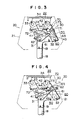
- Fig. 4 shows the click of the click member riding on the contact portion of the sector and an engaged end of the click member got over the engaging end of a pole member;
- Fig. 5 shows the click member releases from the sector, under which headrest body and frame are being returned to their initial states, with the engaged end of the click member got over the engaging end of the pole member; and
- Fig. 6 shows the headrest body and frame returned and the click member released from the pole member.
- Fig. 2 shows an embodiment of the present invention. A support bracket 19 is fixed the upper end portion of a
support stay 19 erected from the seat back of a seat A. Aheadrest body 20 is supported, movable forward and backward, by thesupport bracket 19 through alink mechanism 30. - The
headrest body 20 comprises covering aheadrest frame 21 with pad or the like and both of theheadrest body 20 andframe 21 are supported, movable forward and backward, on the support stay 18 through the support bracket 19 andlink mechanism 30. - The
link mechanism 30 comprises the support bracket 19 a firstswing link member 40 whose base is pivoted on the front portion of thesupport bracket 19 through apivot shaft 31, a secondswing link member 50 whose base is pivoted on the back portion of thesupport bracket 19 through apivot shaft 32, and abracket 22 fixed to theheadrest frame 21 and on which the front ends of the first and secondswing link members 40 and 50 erected in parallel from thesupport bracket 19 are pivoted throughpivot shafts swing link member 40 is arranged parallel to the secondswing link member 50, thelink mechanism 30 is called parallel link mechanism, but it is not necessarily needed that the first and secondswing link members - The
headrest body 20 is urged in right direction in Fig. 1 by means of a spring (not shown). - A
sector 41 is located at the base of the firstswing link member 40 andteeth 42 are formed on one side of thesector 41, taking thepivot shaft 31 as their center. - Pivoted on the
support bracket 19 which supports the firstswing link member 40 through thepivot shaft 31, is aclick member 60 through thepivot shaft 32. Thesesector 41 and clickmember 60 form a lock mechanism. - The
click member 60 has aclick 61 which can get over theteeth 42 of thesector 41 not in a direction but in the reverse direction thereof. Theclick 61 is urged by aspring 62 to engage theteeth 42 of thesector 41. - The
sector 41 has a pushingportion 43 continuous from its last tooth and contacted with theclick 61 of theclick member 60 to release theclick 61 from theteeth 42 of thesector 41 when theheadrest body 20 is moved to the stop end of its moving stroke. Namely, the pushingportion 43 of thesector 41 serves as a release member for swinging theclick member 60 to release theclick 61 from theteeth 42 of thesector 41. - A
pole member 70 is pivoted on the secondswing link member 50 through thepivot shaft 34 and serves as a holder means for holding theclick 61 of theclick member 60 released from theteeth 42 of thesector 41 when theheadrest body 20 is moved to the stop end of its moving stroke. The release member and holder means form a lock release mechanism. - The
pole member 70 has anengaging end 71 engageable with anengaged end 63 of theclick member 60 and urged by aspring 72 in clockwise direction in which astopper 73 is contacted with a part of the secondswing link member 50. Theengaging end 71 has aside 74 engaged with and released from theend 63 of theclick member 60. - A returning
means 23 is erected on thebracket 22 fixed to theheadrest frame 21 and saves to engage theside 74 to release thepole member 70 when theheadrest body 20 which has released at the stop end of its moving stroke is returned to the start end or its initial position. - In Fig. 2, the
headrest body 20 andframe 21 are at the start end of their moving stroke, and theclick 61 of theclick member 60 is engaged with the start end of theteeth 42 of thesector 41 to prevent both of theheadrest frame 21 andbody 20 from moving in right direction in Fig. 3. The headrest body and frame are stopped like this whichever teeth of thesector 41 theclick 61 may be engaged with. - In the case where the position of the
headrest body 20 is to be adjusted, theheadrest body 20 is grasped by a hand and force is applied to theheadrest body 20 to move it in left direction in Fig. 3. Thelink mechanism 30 is thus made operative, following the movement of theheadrest body 20 andframe 21, to swing the firstswing link member 40 andsector 41. When the force applied is stronger than a predetermined one, theclick 61 of theclick member 60 rides on the side of a tooth and then gets over the tooth. Theclick 61 of theclick member 60 gets over the succeeding teeth one after another like this. - When the
headrest body 20 is released from the hand at a desired position, theclick 61 of theclick member 60 is engaged with that tooth of thesector 41 which corresponds to the desired position, to stop theheadrest frame 21 andbody 20, so that the position of theheadrest body 20 can be adjusted. - When the
headrest body 20 is released, passing over the desired position, it is largely moved in left direction in Fig. 2. Theclick member 60 is thus swung, causing itsclick 61 to be passed over the last end of theteeth 42 and contacted with the pushingportion 43, as shown in Fig. 3, and then released from theteeth 42, as shown in Fig. 4. - The
end 63 of theclick member 60 is contacted with theengaging end 71 of thepole member 70 almost at the same time and gotten over theengaging end 71, swinging thepole member 70 in anti-clockwise direction. - When the
headrest body 20 andframe 21 are then moved in left direction from their positions shown in Fig. 4, theengaged end 63 is again engaged with theengaging end 71 of thepole member 70, as shown in Fig. 5, to hold theclick 61 of theclick member 60 released from theteeth 42 of thesector 41, so that both of theheadrest body 20 andframe 21 can be returned to the start end of their moving stroke (Fig. 5). - When the
headrest body 20 andframe 21 are returned to the start end of their moving stroke, the returning means 23 on thebracket 22 fixed to theheadrest frame 21 is contacted with theside 74 to swing thepole member 70 in anti-clockwise direction. As the result, theend 63 of theclick member 60 is released from theengaging end 71 of thepole member 70, while itsclick 61 is engaged with the start end of theteeth 42 of thesector 41 due to the action of thespring 62, thereby causing theheadrest body 20 to be returned as shown in Fig. 2. - When the
headrest 20 andframe 21 are again moved in left direction in Fig. 3, the position of theheadrest body 20 can be adjusted as described above. - The mechanism for holding the headrest body by means of the sector, click member, pole member and the like may be arranged, taking any of the pivot shafts 31 - 34 as its center, and these members may be attached to those members, which form the link mechanism, to achieve the above-described function.
- Although one embodiment of the present invention has been described, it should be understood that various modifications can be made without departing from the scope and spirit of the present invention.
Claims (10)
Applications Claiming Priority (2)
| Application Number | Priority Date | Filing Date | Title |
|---|---|---|---|
| JP188437/84U | 1984-12-12 | ||
| JP1984188437U JPS61102153U (en) | 1984-12-12 | 1984-12-12 |
Publications (3)
| Publication Number | Publication Date |
|---|---|
| EP0188732A2 true EP0188732A2 (en) | 1986-07-30 |
| EP0188732A3 EP0188732A3 (en) | 1987-06-03 |
| EP0188732B1 EP0188732B1 (en) | 1990-08-29 |
Family
ID=16223660
Family Applications (1)
| Application Number | Title | Priority Date | Filing Date |
|---|---|---|---|
| EP85115822A Expired - Lifetime EP0188732B1 (en) | 1984-12-12 | 1985-12-12 | Headrest |
Country Status (4)
| Country | Link |
|---|---|
| US (1) | US4733913A (en) |
| EP (1) | EP0188732B1 (en) |
| JP (1) | JPS61102153U (en) |
| DE (1) | DE3579440D1 (en) |
Cited By (3)
| Publication number | Priority date | Publication date | Assignee | Title |
|---|---|---|---|---|
| WO1998016406A1 (en) * | 1996-10-14 | 1998-04-23 | Acen Andonov | Headrest |
| EP2711243A1 (en) * | 2012-09-25 | 2014-03-26 | Centre D'etude Et De Recherche Pour L'automobile (Cera) | Headrest for an automobile seat |
| CN107444207A (en) * | 2016-05-30 | 2017-12-08 | 比亚迪股份有限公司 | Car seat headrest governor motion and automotive seat |
Families Citing this family (33)
| Publication number | Priority date | Publication date | Assignee | Title |
|---|---|---|---|---|
| DE8717434U1 (en) * | 1987-08-14 | 1988-10-27 | Siemens AG, 1000 Berlin und 8000 München | Motor-adjustable headrest for a dental chair |
| JPH0734620Y2 (en) * | 1988-02-29 | 1995-08-09 | 三菱自動車工業株式会社 | Headrest front-back adjustment device |
| US5095257A (en) * | 1989-12-11 | 1992-03-10 | Tachi-S Co., Ltd. | Method and device for controlling headrest in automotive seat |
| US5020855A (en) * | 1990-02-09 | 1991-06-04 | Prince Corporation | Adjustable headrest |
| DE4034118A1 (en) * | 1990-04-06 | 1991-10-10 | Grammer Ag | Adjustable headrest for motor vehicle seat - is supported on vertical bars with double right-angled bends |
| US5257853A (en) * | 1992-02-07 | 1993-11-02 | Hoover Universal, Inc. | Headrest armature for seats |
| DE4221610C2 (en) * | 1992-07-01 | 1997-05-28 | Grammer Ag | Headrest for a seat, in particular for a vehicle seat |
| US5228749A (en) * | 1992-07-22 | 1993-07-20 | Lear Seating Corporation | Pivoting headrest having snap-together body sections |
| US5236246A (en) * | 1992-07-22 | 1993-08-17 | Lear Seating Corporation | Adjustable headrest having integral pivot connection |
| US5236245A (en) * | 1992-07-22 | 1993-08-17 | Lear Seating Corporation | Tilt-adjustable headrest having central ratcheting mechanism |
| US5282668A (en) * | 1992-10-13 | 1994-02-01 | Lear Seating Corporation | Child restraint seat including pivotal headrest assembly |
| US5397168A (en) * | 1993-09-02 | 1995-03-14 | Bemis Manufacturing Company | Chair with adjustable backrest |
| KR19980024703U (en) * | 1996-10-31 | 1998-07-25 | 정해일 | Tilting device for car headrest |
| EP0925994A1 (en) * | 1997-12-24 | 1999-06-30 | Gestind M.B. Manifattura Di Bruzolo S.P.A | A headrest for motor verhicle seats |
| EP0976608A1 (en) * | 1998-07-09 | 2000-02-02 | Gestind M.B. Manifattura Di Bruzolo S.P.A | A headrest for motor-vehicle seats |
| FR2792265B1 (en) * | 1999-04-13 | 2001-06-15 | Faure Bertrand Equipements Sa | MOTOR VEHICLE SEAT WITH RETRACTABLE HEADREST |
| JP2001097086A (en) * | 1999-09-28 | 2001-04-10 | Combi Corp | child seat |
| US6767064B2 (en) * | 2002-02-27 | 2004-07-27 | Lear Corporation | Translatable head restraint for automotive seat backrest |
| KR100510152B1 (en) * | 2003-04-14 | 2005-08-26 | 주식회사 우보테크 | Headrest for cars |
| ATE464871T1 (en) * | 2005-10-10 | 2010-05-15 | Degonda Rehab Sa | ADJUSTABLE HEADREST UNIT |
| KR100726884B1 (en) | 2005-11-01 | 2007-06-13 | 류흥석 | Car seat with safety device |
| KR100730483B1 (en) * | 2005-12-22 | 2007-06-20 | 최순봉 | Car Headrests |
| DE102009019439B3 (en) * | 2008-11-10 | 2010-06-24 | Grammer Ag | Headrest for vehicle seats |
| US8382206B2 (en) * | 2010-01-21 | 2013-02-26 | Bae Industries, Inc. | Forward incrementally adjustable ratchet headrest |
| DE102010010537B4 (en) * | 2010-03-05 | 2012-10-25 | Johnson Controls Gmbh | Headrest, in particular for a motor vehicle |
| CN107901807B (en) | 2012-09-26 | 2020-04-24 | 提爱思科技股份有限公司 | Head rest |
| JP5902847B1 (en) * | 2015-05-14 | 2016-04-13 | 備前発条株式会社 | Headrest |
| KR101694910B1 (en) * | 2015-12-23 | 2017-01-10 | 주식회사 우보테크 | Vehicle headrest sliding device |
| US10099591B2 (en) * | 2016-12-01 | 2018-10-16 | David Flynn | Dual configuration headrest system |
| DE102018106698A1 (en) * | 2018-03-21 | 2019-09-26 | Grammer Ag | headrest |
| DE102018109611B4 (en) * | 2018-04-10 | 2022-04-21 | Grammer Aktiengesellschaft | headrest |
| DE102018005316A1 (en) * | 2018-07-05 | 2020-01-09 | Grammer Aktiengesellschaft | headrest |
| JP6579535B1 (en) * | 2019-03-14 | 2019-09-25 | 備前発条株式会社 | Headrest |
Family Cites Families (8)
| Publication number | Priority date | Publication date | Assignee | Title |
|---|---|---|---|---|
| US979149A (en) * | 1906-04-05 | 1910-12-20 | Edgar A Gay | Furniture attachment. |
| US2812802A (en) * | 1955-08-09 | 1957-11-12 | Nat Seating Co | Adjustable head rest |
| US2828810A (en) * | 1956-04-09 | 1958-04-01 | American Seating Co | Adjustable headrest |
| JPS54127762A (en) * | 1978-03-24 | 1979-10-03 | Aisin Seiki | Frontttoorear direction adjuster for safety pillow of automobile |
| JPS6216930Y2 (en) * | 1979-08-27 | 1987-04-28 | ||
| US4307913A (en) * | 1980-06-02 | 1981-12-29 | Milsco Manufacturing Company | Adjustable arm-rest for vehicle seat |
| US4558903A (en) * | 1983-09-22 | 1985-12-17 | Tachikawa Spring Co., Ltd. | Angle adjustment device of a movable body for a vehicle seat |
| JPS60167558U (en) * | 1984-04-13 | 1985-11-07 | アイシン精機株式会社 | Vertically movable headrest device |
-
1984
- 1984-12-12 JP JP1984188437U patent/JPS61102153U/ja active Pending
-
1985
- 1985-12-11 US US06/807,601 patent/US4733913A/en not_active Expired - Fee Related
- 1985-12-12 EP EP85115822A patent/EP0188732B1/en not_active Expired - Lifetime
- 1985-12-12 DE DE8585115822T patent/DE3579440D1/en not_active Expired - Lifetime
Cited By (4)
| Publication number | Priority date | Publication date | Assignee | Title |
|---|---|---|---|---|
| WO1998016406A1 (en) * | 1996-10-14 | 1998-04-23 | Acen Andonov | Headrest |
| EP2711243A1 (en) * | 2012-09-25 | 2014-03-26 | Centre D'etude Et De Recherche Pour L'automobile (Cera) | Headrest for an automobile seat |
| FR2995842A1 (en) * | 2012-09-25 | 2014-03-28 | Cera | HEADREST FOR THE SEAT OF A MOTOR VEHICLE |
| CN107444207A (en) * | 2016-05-30 | 2017-12-08 | 比亚迪股份有限公司 | Car seat headrest governor motion and automotive seat |
Also Published As
| Publication number | Publication date |
|---|---|
| EP0188732B1 (en) | 1990-08-29 |
| EP0188732A3 (en) | 1987-06-03 |
| US4733913A (en) | 1988-03-29 |
| JPS61102153U (en) | 1986-06-30 |
| DE3579440D1 (en) | 1990-10-04 |
Similar Documents
| Publication | Publication Date | Title |
|---|---|---|
| US4733913A (en) | Headrest | |
| US3893730A (en) | Seat positioner | |
| US3840268A (en) | Vehicle seats and to mechanism therefor | |
| US4660886A (en) | Reclining seat mechanism | |
| JPS6216930Y2 (en) | ||
| US4223946A (en) | Vehicle seat fitting | |
| EP0832780A1 (en) | Bi-directional inertial latch | |
| JPH0257923B2 (en) | ||
| JPS6331838A (en) | Seat slide device | |
| JPH07156704A (en) | Reclining seat | |
| JPH1099157A (en) | Seat reclining device | |
| JPH05229376A (en) | Vehicle seat adjustment device | |
| US6722734B2 (en) | Locking assembly for a rocking chair | |
| JPH0366882B2 (en) | ||
| JPH0411868Y2 (en) | ||
| JPS6010432Y2 (en) | Seat reclining device | |
| JPS6319224Y2 (en) | ||
| JPS6210189Y2 (en) | ||
| JPS646134Y2 (en) | ||
| JPH024612Y2 (en) | ||
| JPH0623465Y2 (en) | Vehicle seat | |
| EP0976606A1 (en) | Seat reclining system | |
| JPS6345959Y2 (en) | ||
| JPS5911645Y2 (en) | Reclining adjuster for vehicle seats, etc. | |
| JPH0537869Y2 (en) |
Legal Events
| Date | Code | Title | Description |
|---|---|---|---|
| PUAI | Public reference made under article 153(3) epc to a published international application that has entered the european phase |
Free format text: ORIGINAL CODE: 0009012 |
|
| AK | Designated contracting states |
Kind code of ref document: A2 Designated state(s): DE FR GB |
|
| PUAL | Search report despatched |
Free format text: ORIGINAL CODE: 0009013 |
|
| AK | Designated contracting states |
Kind code of ref document: A3 Designated state(s): DE FR GB |
|
| 17P | Request for examination filed |
Effective date: 19870716 |
|
| 17Q | First examination report despatched |
Effective date: 19880219 |
|
| RAP1 | Party data changed (applicant data changed or rights of an application transferred) |
Owner name: IKEDA BUSSAN CO., LTD. |
|
| GRAA | (expected) grant |
Free format text: ORIGINAL CODE: 0009210 |
|
| AK | Designated contracting states |
Kind code of ref document: B1 Designated state(s): DE FR GB |
|
| REF | Corresponds to: |
Ref document number: 3579440 Country of ref document: DE Date of ref document: 19901004 |
|
| ET | Fr: translation filed | ||
| PLBE | No opposition filed within time limit |
Free format text: ORIGINAL CODE: 0009261 |
|
| STAA | Information on the status of an ep patent application or granted ep patent |
Free format text: STATUS: NO OPPOSITION FILED WITHIN TIME LIMIT |
|
| 26N | No opposition filed | ||
| PGFP | Annual fee paid to national office [announced via postgrant information from national office to epo] |
Ref country code: GB Payment date: 19921124 Year of fee payment: 8 |
|
| PGFP | Annual fee paid to national office [announced via postgrant information from national office to epo] |
Ref country code: FR Payment date: 19921208 Year of fee payment: 8 |
|
| PGFP | Annual fee paid to national office [announced via postgrant information from national office to epo] |
Ref country code: DE Payment date: 19930129 Year of fee payment: 8 |
|
| PG25 | Lapsed in a contracting state [announced via postgrant information from national office to epo] |
Ref country code: GB Effective date: 19931212 |
|
| GBPC | Gb: european patent ceased through non-payment of renewal fee |
Effective date: 19931212 |
|
| PG25 | Lapsed in a contracting state [announced via postgrant information from national office to epo] |
Ref country code: FR Effective date: 19940831 |
|
| PG25 | Lapsed in a contracting state [announced via postgrant information from national office to epo] |
Ref country code: DE Effective date: 19940901 |
|
| REG | Reference to a national code |
Ref country code: FR Ref legal event code: ST |