EP0188630B1 - Air conditioning apparatus - Google Patents
Air conditioning apparatus Download PDFInfo
- Publication number
- EP0188630B1 EP0188630B1 EP84309057A EP84309057A EP0188630B1 EP 0188630 B1 EP0188630 B1 EP 0188630B1 EP 84309057 A EP84309057 A EP 84309057A EP 84309057 A EP84309057 A EP 84309057A EP 0188630 B1 EP0188630 B1 EP 0188630B1
- Authority
- EP
- European Patent Office
- Prior art keywords
- super
- heat exchanger
- valve
- indoor units
- temperature
- Prior art date
- Legal status (The legal status is an assumption and is not a legal conclusion. Google has not performed a legal analysis and makes no representation as to the accuracy of the status listed.)
- Expired - Lifetime
Links
- 238000004378 air conditioning Methods 0.000 title claims description 8
- 239000003507 refrigerant Substances 0.000 claims description 141
- 239000007788 liquid Substances 0.000 claims description 139
- 238000010438 heat treatment Methods 0.000 claims description 85
- 238000001816 cooling Methods 0.000 claims description 72
- 238000004781 supercooling Methods 0.000 claims description 41
- 230000005855 radiation Effects 0.000 claims description 7
- 230000004044 response Effects 0.000 claims description 5
- 238000010586 diagram Methods 0.000 description 14
- 238000009825 accumulation Methods 0.000 description 7
- 230000007246 mechanism Effects 0.000 description 4
- XLYOFNOQVPJJNP-UHFFFAOYSA-N water Substances O XLYOFNOQVPJJNP-UHFFFAOYSA-N 0.000 description 4
- 238000010276 construction Methods 0.000 description 3
- 238000011068 loading method Methods 0.000 description 3
- 230000009467 reduction Effects 0.000 description 3
- 230000000694 effects Effects 0.000 description 2
- 230000006870 function Effects 0.000 description 2
- 229910052751 metal Inorganic materials 0.000 description 2
- 238000010926 purge Methods 0.000 description 2
- 230000008054 signal transmission Effects 0.000 description 2
- 229940002865 4-way Drugs 0.000 description 1
- 230000008859 change Effects 0.000 description 1
- 230000003750 conditioning effect Effects 0.000 description 1
- 230000006872 improvement Effects 0.000 description 1
- 230000002265 prevention Effects 0.000 description 1
- 238000005057 refrigeration Methods 0.000 description 1
- 239000012808 vapor phase Substances 0.000 description 1
Images


Classifications
-
- F—MECHANICAL ENGINEERING; LIGHTING; HEATING; WEAPONS; BLASTING
- F24—HEATING; RANGES; VENTILATING
- F24F—AIR-CONDITIONING; AIR-HUMIDIFICATION; VENTILATION; USE OF AIR CURRENTS FOR SCREENING
- F24F3/00—Air-conditioning systems in which conditioned primary air is supplied from one or more central stations to distributing units in the rooms or spaces where it may receive secondary treatment; Apparatus specially designed for such systems
- F24F3/06—Air-conditioning systems in which conditioned primary air is supplied from one or more central stations to distributing units in the rooms or spaces where it may receive secondary treatment; Apparatus specially designed for such systems characterised by the arrangements for the supply of heat-exchange fluid for the subsequent treatment of primary air in the room units
- F24F3/065—Air-conditioning systems in which conditioned primary air is supplied from one or more central stations to distributing units in the rooms or spaces where it may receive secondary treatment; Apparatus specially designed for such systems characterised by the arrangements for the supply of heat-exchange fluid for the subsequent treatment of primary air in the room units with a plurality of evaporators or condensers
-
- F—MECHANICAL ENGINEERING; LIGHTING; HEATING; WEAPONS; BLASTING
- F24—HEATING; RANGES; VENTILATING
- F24F—AIR-CONDITIONING; AIR-HUMIDIFICATION; VENTILATION; USE OF AIR CURRENTS FOR SCREENING
- F24F1/00—Room units for air-conditioning, e.g. separate or self-contained units or units receiving primary air from a central station
- F24F1/0007—Indoor units, e.g. fan coil units
- F24F1/0071—Indoor units, e.g. fan coil units with means for purifying supplied air
-
- F—MECHANICAL ENGINEERING; LIGHTING; HEATING; WEAPONS; BLASTING
- F24—HEATING; RANGES; VENTILATING
- F24F—AIR-CONDITIONING; AIR-HUMIDIFICATION; VENTILATION; USE OF AIR CURRENTS FOR SCREENING
- F24F11/00—Control or safety arrangements
- F24F11/62—Control or safety arrangements characterised by the type of control or by internal processing, e.g. using fuzzy logic, adaptive control or estimation of values
- F24F11/63—Electronic processing
-
- F—MECHANICAL ENGINEERING; LIGHTING; HEATING; WEAPONS; BLASTING
- F24—HEATING; RANGES; VENTILATING
- F24F—AIR-CONDITIONING; AIR-HUMIDIFICATION; VENTILATION; USE OF AIR CURRENTS FOR SCREENING
- F24F11/00—Control or safety arrangements
- F24F11/70—Control systems characterised by their outputs; Constructional details thereof
- F24F11/80—Control systems characterised by their outputs; Constructional details thereof for controlling the temperature of the supplied air
- F24F11/83—Control systems characterised by their outputs; Constructional details thereof for controlling the temperature of the supplied air by controlling the supply of heat-exchange fluids to heat-exchangers
- F24F11/84—Control systems characterised by their outputs; Constructional details thereof for controlling the temperature of the supplied air by controlling the supply of heat-exchange fluids to heat-exchangers using valves
-
- F—MECHANICAL ENGINEERING; LIGHTING; HEATING; WEAPONS; BLASTING
- F24—HEATING; RANGES; VENTILATING
- F24F—AIR-CONDITIONING; AIR-HUMIDIFICATION; VENTILATION; USE OF AIR CURRENTS FOR SCREENING
- F24F11/00—Control or safety arrangements
- F24F11/88—Electrical aspects, e.g. circuits
-
- F—MECHANICAL ENGINEERING; LIGHTING; HEATING; WEAPONS; BLASTING
- F25—REFRIGERATION OR COOLING; COMBINED HEATING AND REFRIGERATION SYSTEMS; HEAT PUMP SYSTEMS; MANUFACTURE OR STORAGE OF ICE; LIQUEFACTION SOLIDIFICATION OF GASES
- F25B—REFRIGERATION MACHINES, PLANTS OR SYSTEMS; COMBINED HEATING AND REFRIGERATION SYSTEMS; HEAT PUMP SYSTEMS
- F25B13/00—Compression machines, plants or systems, with reversible cycle
-
- F—MECHANICAL ENGINEERING; LIGHTING; HEATING; WEAPONS; BLASTING
- F25—REFRIGERATION OR COOLING; COMBINED HEATING AND REFRIGERATION SYSTEMS; HEAT PUMP SYSTEMS; MANUFACTURE OR STORAGE OF ICE; LIQUEFACTION SOLIDIFICATION OF GASES
- F25B—REFRIGERATION MACHINES, PLANTS OR SYSTEMS; COMBINED HEATING AND REFRIGERATION SYSTEMS; HEAT PUMP SYSTEMS
- F25B41/00—Fluid-circulation arrangements
- F25B41/30—Expansion means; Dispositions thereof
- F25B41/31—Expansion valves
- F25B41/34—Expansion valves with the valve member being actuated by electric means, e.g. by piezoelectric actuators
- F25B41/35—Expansion valves with the valve member being actuated by electric means, e.g. by piezoelectric actuators by rotary motors, e.g. by stepping motors
-
- F—MECHANICAL ENGINEERING; LIGHTING; HEATING; WEAPONS; BLASTING
- F24—HEATING; RANGES; VENTILATING
- F24F—AIR-CONDITIONING; AIR-HUMIDIFICATION; VENTILATION; USE OF AIR CURRENTS FOR SCREENING
- F24F11/00—Control or safety arrangements
- F24F11/30—Control or safety arrangements for purposes related to the operation of the system, e.g. for safety or monitoring
-
- F—MECHANICAL ENGINEERING; LIGHTING; HEATING; WEAPONS; BLASTING
- F24—HEATING; RANGES; VENTILATING
- F24F—AIR-CONDITIONING; AIR-HUMIDIFICATION; VENTILATION; USE OF AIR CURRENTS FOR SCREENING
- F24F2110/00—Control inputs relating to air properties
- F24F2110/10—Temperature
-
- F—MECHANICAL ENGINEERING; LIGHTING; HEATING; WEAPONS; BLASTING
- F24—HEATING; RANGES; VENTILATING
- F24F—AIR-CONDITIONING; AIR-HUMIDIFICATION; VENTILATION; USE OF AIR CURRENTS FOR SCREENING
- F24F2140/00—Control inputs relating to system states
-
- F—MECHANICAL ENGINEERING; LIGHTING; HEATING; WEAPONS; BLASTING
- F24—HEATING; RANGES; VENTILATING
- F24F—AIR-CONDITIONING; AIR-HUMIDIFICATION; VENTILATION; USE OF AIR CURRENTS FOR SCREENING
- F24F2221/00—Details or features not otherwise provided for
- F24F2221/54—Heating and cooling, simultaneously or alternatively
-
- F—MECHANICAL ENGINEERING; LIGHTING; HEATING; WEAPONS; BLASTING
- F25—REFRIGERATION OR COOLING; COMBINED HEATING AND REFRIGERATION SYSTEMS; HEAT PUMP SYSTEMS; MANUFACTURE OR STORAGE OF ICE; LIQUEFACTION SOLIDIFICATION OF GASES
- F25B—REFRIGERATION MACHINES, PLANTS OR SYSTEMS; COMBINED HEATING AND REFRIGERATION SYSTEMS; HEAT PUMP SYSTEMS
- F25B2313/00—Compression machines, plants or systems with reversible cycle not otherwise provided for
- F25B2313/023—Compression machines, plants or systems with reversible cycle not otherwise provided for using multiple indoor units
-
- F—MECHANICAL ENGINEERING; LIGHTING; HEATING; WEAPONS; BLASTING
- F25—REFRIGERATION OR COOLING; COMBINED HEATING AND REFRIGERATION SYSTEMS; HEAT PUMP SYSTEMS; MANUFACTURE OR STORAGE OF ICE; LIQUEFACTION SOLIDIFICATION OF GASES
- F25B—REFRIGERATION MACHINES, PLANTS OR SYSTEMS; COMBINED HEATING AND REFRIGERATION SYSTEMS; HEAT PUMP SYSTEMS
- F25B2313/00—Compression machines, plants or systems with reversible cycle not otherwise provided for
- F25B2313/027—Compression machines, plants or systems with reversible cycle not otherwise provided for characterised by the reversing means
- F25B2313/02741—Compression machines, plants or systems with reversible cycle not otherwise provided for characterised by the reversing means using one four-way valve
-
- Y—GENERAL TAGGING OF NEW TECHNOLOGICAL DEVELOPMENTS; GENERAL TAGGING OF CROSS-SECTIONAL TECHNOLOGIES SPANNING OVER SEVERAL SECTIONS OF THE IPC; TECHNICAL SUBJECTS COVERED BY FORMER USPC CROSS-REFERENCE ART COLLECTIONS [XRACs] AND DIGESTS
- Y02—TECHNOLOGIES OR APPLICATIONS FOR MITIGATION OR ADAPTATION AGAINST CLIMATE CHANGE
- Y02B—CLIMATE CHANGE MITIGATION TECHNOLOGIES RELATED TO BUILDINGS, e.g. HOUSING, HOUSE APPLIANCES OR RELATED END-USER APPLICATIONS
- Y02B30/00—Energy efficient heating, ventilation or air conditioning [HVAC]
- Y02B30/70—Efficient control or regulation technologies, e.g. for control of refrigerant flow, motor or heating
Definitions
- the expansion vave 58 utilizes a bi-metallic element and an electric heater for heating said bi-metallic element the valve opening being controlled by adjustment of the current through said electric heater during both cooling and heating operations. It is therefore not necessary to provide separate expansion valves for cooling and heating, which simplifies the refrigeration circuit to that extent.
- the expansion valve 58 is constructed so as to completely close during cooling and remain fully open during heating operations, it is necessary to provide a solenoid valve 61 in said gas line branch 60.
- the expansion valve 58 controls the degree of superheat only during both cooling and heating operations and cannot control the degree of supercooling, especially during heating operations it controls the degree of super-heat of low pressure gaseous refrigerant at the outlet of said supply-side heat exchanger 53 of the outdoor unit A, it is impossible to provide an appropriate refrigerant distribution to each of the indoor units B. Nowhere in the prior art is there any specific disclosure of any system which can provide appropriate refrigerant distribution to each of the indoor units B, whilst still controlling the degree of super-heat.
- the compressed gas In a heating mode, the compressed gas first passes through the indoor exchanger which operates as a condenser, a portion of the gas flow then travelling in the opposite direction to that travelled in the cooling mode so as to enter the outdoor exchanger, which is operating as a condenser, a further portion passing through a branch line to a container or reservoir.
- the opening of the motorized valves connected to the operating indoor units can be controlled by the loading applied to each respective indoor unit but it may also be controlled in accordance with the number of indoor units in operation.
- a motorized valve (hereinafter referred to as the second or secondary motorized valve) is preferably used as the control means and when such a second motorized valve is used, it is possible for this to be arranged so that the second motorized valve controls super-cooling at said supply-side heat exchanger outlet during cooling and super- heat at said heat exchanger outlet during heating operations.
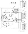
- Fig. 1 shows a typical embodiment of the present invention wherein the refrigerant circuit comprises an outdoor unitA having a compressor 1, a 4-way valve 2, a supply-side heat exchanger 3, a liquid refrigerant line main 4, a plurality of liquid line branches 5 branching out of said liquid line main 4, gaseous refrigerant line main 6 and a plurality of gas line branches 7 branching out of said gas line main and a plurality of indoor units B each having a consumer-side heat exchanger and a fan which are connected in parallel between said liquid line branches 5 and said gas line branches 7 through a plurality of connection pipes C.
- the system is capable of providing cooling or heating.
- the second sensing circuit 20 also serves as the second temperature sensing means by mounting a fourth temperature sensor THe between said temperature sensing circuit heat exchanger 21 and said pressure reducing mechanism 22 in order to sense the saturation temperature To of high pressure liquid refrigerant passing through said heat exchanger 21.
- the second sensing circuit 20 is provided on the outdoor unit A, the first temperature sensors TH 1 ⁇ TH 3 mounted in the gas line branches 7, the third temperature sensors TH 4 ⁇ TH 6 mounted in the liquid line branches 5, all the wiring connecting said first and third temperature sensors TH 1 ⁇ TH 6 and the valve control means of said motorized valves EV,-EV 3 for signal transmissions are housed within the outdoor Unit A, which avoids the need for any control wiring between the outdoor and indoor units.
- the motorized valves EV 1 ⁇ EV 3 are mounted in the liquid line branches only and no motorized valves or solenoid valves as used in conventional systems require to be mounted in the gas line branches 7, it is possible to reduce the number of components correspondingly and thereby simplify the refigerant circuit. Since the motorized valves EV,-EV 3 completely close during cooling and open to only a small opening during heating operations for non-operating units B, no liquid accumulation takes place in the non-operating indoor units B.
- the motorized valve EV 1 ⁇ EV 3 is shut down to a small opening, i.e. an opening sufficiently small to admit liquid refrigerant condensing as a result of natural radiation.
- the size of the small residual opening of the motorized valve EV 1 ⁇ EV 3 during heating operations may be fixed at a suitably small predetermined valve.
- the first sensing circuit 16 of this embodiment is for control of valve opening of the second motorized valve EV 4 and as stated above, contains a pressure reducing device 17 such as a capillary tube and the second temperature sensor THe is mounted in the first sensing circuit 16 between said pressure reducing mechanism 17 and said suction line 19, and a fifth temperature sensor TH 7 is mounted on the suction line 19 in order to sense low pressure gaseous refrigerant temperature T 7 .
- a pressure reducing device 17 such as a capillary tube
- the second temperature sensor THe is mounted in the first sensing circuit 16 between said pressure reducing mechanism 17 and said suction line 19
- a fifth temperature sensor TH 7 is mounted on the suction line 19 in order to sense low pressure gaseous refrigerant temperature T 7 .
- a bypass circuit bypassing said conventional superheat control valve is provided in said liquid line main 4 and a check valve is mounted on said bypass circuit to pass refrigerant during cooling operations.
- first motorized valves EV 1 ⁇ EV 3 corresponding to the non-operating units are completely closed (stop 106) and the first motorized valves EV 1 ⁇ EV 3 corresponding to the operating units are controlled to a predetermined opening in accordance with the pulse number changing with the number of indoor units B operating (step 107).
- the second motorized valve EV 4 is fully opened (step 108).
- Fig. 6 is the flow chart for heating operations, which starts with sensing of heating mode operation as for the cooling operations.
- the operational status checked out step 201
- the existence of any change in the operational status is judged (step 202).
- the first and second motorized valves EV I -EV 3 , EV 4 are cut off from control thereof (steps 203, 204).
- the first motorized valves EV 1 ⁇ EV 3 are controlled at a given opening in accordance with the pulse number which changes with the number of indoor units B operating (step 207).
- the deviation E 1 is calculated (step 209) and when the absolute value of this deviation E, is largerthan 1°C and said deviation E 1 is less than 0, the second motorized valve EV 4 is closed by one predetermined notch (step 210) and when said deviation is more than 0, the second motorized valve EV 4 is opened by one predetermined notch and thereby the deviation E, of said low pressure gaseous refrigerant super-heat can be controlled within ⁇ 1°C of the target superheat SH which is set to have 0°-3°C at the outlet of the supply-side heat exchanger 3.
- the second motorized valve EV 4 may be controlled during heating, to a pre-determined opening so as to obtain appropriate superheat.
- said motorized valve EV 4 may operate so as to control super-cooling of high pressure liquid refrigerant at the supply-side heat exchanger 3 outlet during cooling and an externally equalizing or internally equalizing expansion valve may also be applied to super-cooling control.
- the control system which controls the first motorized valve EV 1 ⁇ EV 3 mounted in each liquid line branch 5 and the second motorized valve EV 4 mounted on the liquid line main 4 for controling superheat of low pressure gaseous refrigerant at the supply-side heat exchanger 3 outlet during heating is basically the same as that of the second embodiment shown in Fig. 4. The difference is the following additional hook-up so constructed that as shown in Fig. 8, on the input side of central processing unit CPU of said controller30, said first and third temperature sensors TH 1 ⁇ TH 6 are connected and said central processing unit CPU incorporates the following four functions:
- This control operation is the same for both cooling and heating operations. After this predetermined period, the operation proceeds as follows. During cooling operations as shown in the flow chart of Fig. 9, the temperatures of low pressure gaseous refrigerant T,-T 3 flowing through said gas line branches 7 from the respective operating indoor units B are sensed by the first temperature sensors TH 1 ⁇ TH 3 (step 109) and the saturation temperature Te of low pressure gaseous refrigerant is sensed by the second temperature sensor THe (step 109).
- the minimum pulse number in the closing direction is set at about 50 pulses and the maximum pulse number at about 200 pulses.
- the refrigerant circuit of the fourth embodiment shown in Fig. 11 is basically similar to those of the second and third embodiments shown in Figs. 3 and 7, respectively.
- the difference is that in the third embodiment shown in Fig. 7, the sixth temperature sensor TH 8 and the seventh temperature sensor TH 9 are provided, in the liquid line 4, in order to sense respectively, high pressure liquid refrigerant temperature T 8 at the supply-side heat exchanger 3 outlet and condensing temperature T c therein and thereby super- cooling is also controlled using the second motorized valve EV 4 . Therefore, the control system for the first motorized valves EV,-EV 3 and the second motorized valve differs, as shown in Fig.
- the second motorized valve EV 4 When the deviation E 2 is positive and the absolute value thereof larger than 1, the second motorized valve EV 4 is modulated so as to close by one notch (step 315) and when it is negative and the absolute value thereof larger than 1, the second motorized valve EV 4 is modulated so as to open by one notch (step 316) and thereby super-cooling of said high pressure liquid refrigerant is maintained within ⁇ 1°C of the target super-cooling level by controlling the pulse input into the second motorized valve EV 4 .
- the second motorized valve EV 4 control may be conducted by first controlling the input pulse number (for example to 180 pulses) so as to obtain the proper degree of opening.
- the fifth embodiment shown in Fig. 14 is basically similar to the first embodiment and the main difference from the first embodiment lies in that a parallel circuit of the second motorized valve EV 4 and a check valve 25 are, as in the second embodiment, provided in said liquid line main 4 to control low pressure gaseous refrigerant super-heat at the supply-side heat exchanger 3 outlet during heating; two 4-way valves, i.e.
- first and second 4-way valves 2A, 2B are provided; a domestic hot water supply heat exchanger 43 is provided between the second four-way valve and a receiver 10; the first sensing circuit 16A has a pressure-reducing device 17A provided between the liquid line main 4 and the suction line 19; and a second sensing circuit 20A has a detector heat exchanger 21A provided with one end connected to the line connecting said pressure reducing device 17A with said liquid line main 4 and its other end to the gas line main 6.
- refrigerant is conducted for cooling along the route indicated by the full line arrow, for cooling and providing a domestic hot water supply along the route indicated by the dotted line arrow, for domestic hot water supply (alone) along the route indicated by the chain line arrow, and for heating along the route indicated by double chain line arrow.
Landscapes
- Engineering & Computer Science (AREA)
- Mechanical Engineering (AREA)
- General Engineering & Computer Science (AREA)
- Chemical & Material Sciences (AREA)
- Combustion & Propulsion (AREA)
- Physics & Mathematics (AREA)
- Signal Processing (AREA)
- Thermal Sciences (AREA)
- Fuzzy Systems (AREA)
- Mathematical Physics (AREA)
- Air Conditioning Control Device (AREA)
- Compression-Type Refrigeration Machines With Reversible Cycles (AREA)
Description
- This invention relates to air-conditioning apparatus suitable for use with a plurality of rooms and more particularly to a multi-room type air-conditioner which comprises an outdoor unit having a compressor, 4-way valve and a supply-side heat exchanger, and a plurality of indoor units each having a consumer-side heat exchanger and a fan and is capable of providing cooling or heating by changeover of said 4-way valve.
- Generally in a multi-room type air-conditioner connecting a plurality of indoor units with an outdoor unit, it is common to connect the liquid line and gas line mains of an outdoor unit respectively to a plurality of liquid line and gas line branches corresponding in number to the indoor units connected thereto and to provide a solenoid valve in each branch to switch on and off as the indoor unit comes on or goes off. However, since a solenoid valve is only capable of on and off operation and the valve is fully opened in the operating condition of the unit, it is necessary to provide the indoor unit with a pressure reducing device for cooling and a check valve for bypassing the expansion device and the outdoor unit with a pressure reducing device for heating operations and a check valve for bypassing said pressure reducing mechanism. It is also necessary to provide a by-pass passage to purge, to the low pressure side, refrigerant accumulating in the shut-off indoor unit due to leakage of the gas line branch solenoid valve, which complicates the refrigerant circuit and thus increases its cost.
- One attempt at overcoming these problems by using a system with a thermal-electric expansion valve in lieu of a solenoid valve in a liquid line branch was disclosed in Japanese Unexamined Patent Publication No. Sho 56-49,856. Briefly, this device, which is shown in Fig. 15, comprise a multi-room type air-conditioning apparatus with an outdoor unit A having a
compressor 51, a 4-way valve 52, a supplyside heat exchanger 53 and a plurality of indoor units each having a consumer-side heat exchanger 54 and afan 55 which are connected to the outdoor unit A by means of a plurality of connection pipes C. A thermal-electric expansion valve 58 is provided in eachliquid line branch 57 branching out from the liquid refrigerant line main 56 of the outdoor unit A and asolenoid valve 61 is provided in each gaseousrefrigerant line branch 60 branching out from the gaseousrefrigerant line main 59. Afirst receiver 62 is mounted in said liquid line main andsecondary receivers 63 are mounted in each liquid line branch. Liquid refrigerant is received by thefirst receiver 62 during cooling and thesecondary receivers 63 during heating operations and then fed to saidexpansion valve 58. - The
expansion vave 58 utilizes a bi-metallic element and an electric heater for heating said bi-metallic element the valve opening being controlled by adjustment of the current through said electric heater during both cooling and heating operations. It is therefore not necessary to provide separate expansion valves for cooling and heating, which simplifies the refrigeration circuit to that extent. However, theexpansion valve 58 is constructed so as to completely close during cooling and remain fully open during heating operations, it is necessary to provide asolenoid valve 61 in saidgas line branch 60. Furthermore, since theexpansion valve 58 is used as the pressure reducing mechanism during both cooling and heating operations, it is necessary to provide asecondary receiver 63 in eachliquid line branch 57 and thefirst receiver 62 in theliquid line main 56, as a result of which a substantial reduction of components cannot be expected and the complexity of the piping work cannot be significantly reduced. - Further, since the
expansion valve 58 controls the degree of superheat only during both cooling and heating operations and cannot control the degree of supercooling, especially during heating operations it controls the degree of super-heat of low pressure gaseous refrigerant at the outlet of said supply-side heat exchanger 53 of the outdoor unit A, it is impossible to provide an appropriate refrigerant distribution to each of the indoor units B. Nowhere in the prior art is there any specific disclosure of any system which can provide appropriate refrigerant distribution to each of the indoor units B, whilst still controlling the degree of super-heat. - Another arrangement is described in Swiss Patent Specification No. 583887 which discloses an air-conditioning apparatus for heating or cooling a building. The apparatus includes a compressor and an outdoor and an indoor heat exchanger, the compressor being connected through a 4-way valve and a system of conduits, to both the indoor and outdoor heat exchangers. In a cooling mode, the outdoor exchanger acts as a condenser, compressed gas being condensed and passed through a reduction valve into the indoor exchange where it undergoes a pressure release effect so as to return to the vapor phase and thus remove heat from the air within the building. In a heating mode, the compressed gas first passes through the indoor exchanger which operates as a condenser, a portion of the gas flow then travelling in the opposite direction to that travelled in the cooling mode so as to enter the outdoor exchanger, which is operating as a condenser, a further portion passing through a branch line to a container or reservoir.
- It is an object of the present invention to avoid or minimize one or more of the abovementioned disadvantages. One objective of this invention is to provide a multi-room type air-conditioner wherein it is possible to prevent liquid refrigerant from accumulating in the non-operating indoor unit without using a solenoid valve in each gas line branch as is used in conventional systems and at the same time to control, by means of a motorized valve mounted on each liquid line branch, the degree of super-heat of low pressure gaseous refrigerant at the outlet of the consumer side heat exchanger of each indoor unit during cooling and the degree of supercooling of high pressure liquid refrigerant at the outlet of said consumer side heat exchanger during heating and reduce the drift of the refrigerant flow to be admitted into the operating indoor units during heating operations.
- The present invention provides a multi-room type air-conditioning apparatus comprising an outdoor unit (A) which has a compressor (1), a supply-side heat exchanger (3) and a 4-way valve (2) with two high and two low pressure change- over ports, a plurality of indoor units (B) each of which has a consumer-side heat exchanger (8) and a fan (9) attached thereto, each of said indoor units (B) being connected with said outdoor unit by a first and a second connection pipe (C) and is capable of providing cooling and heating by switching of said 4-way valve (2), said apparatus having a liquid refrigerant line main (4) connected to said supply-side heat exchanger (3) for conducting liquid refrigerant, a plurality of liquid line branches (5) branching out of said liquid line main (4) each branch being connected to a said first connection pipe (C), a discharge pipe (18) connecting the compressor with a high pressure change-over port of the 4-way valve (2), a suction pipe (19) connecting the compressor with a low pressure change-over port of the 4-way valve (2), a gaseous refrigerant line main (6) connected to the supply-side heat exchanger (3) for conducting gaseous refrigerant, a plurality of gas line branches (7) branching out of said gas line main (6) and connected to said second connection pipes (C), the 4-way valve being arranged along said gaseous refrigerant line main (6) and in between the supply side heat exchanger (3) and the plurality of gas line branches (7), motorized valves (EV,-EV3) mounted in each of said liquid line branches (5) with continuously variable valve opening control between fully closed and fully open positions, a super-heat control means (TH,-TH3), for low pressure gaseous refrigerant at the consumer-side heat exchanger (8) outlets during cooling operations of the operating indoor units (B) by adjusting an amount of opening between fully closed and a selected open or partially open condition of said motorized valves (EV,-EV3), a super-cool control means (TH4-THs), for high pressure liquid refrigerant at the consumer-side heat exchanger (8) outlet during heating operations of the operating indoor unit, valve control means provided for each one of said motorized valves (EV,-EV3) each said valve being connected into a respective one of said liquid line branches to an associated indoor unit (B), each valve control means being adapted to operate when the associated indoor unit is non-operating to cause the respective motorized valve to be fully closed during the cooling operation and at least partially open during the heating operation, fan control means formed and arranged for switching off the fans of non-operating indoor units (B) and residual flow valve control means formed and arranged for closing down to a small opening, those of the motorized valves (EV,-EV3) in the liquid line branches (S) connected to non-operating indoor units (B).
- Thus with an apparatus of the present-invention, it is possible, without using a solenoid valve as in the prior art, to prevent liquid refrigerant from accumulating in the non-operating indoor units by closing the motorized valves connected thereto during cooling and closing the motorized valve down to a small opening during heating operations, thereby reducing the number of components and simplifying construction of the apparatus. Furthermore, it is possible, by means of said motorized valves, to control super-heat of the low pressure gaseous refrigerant at the consumer side heat exchanger outlet during cooling and super-cooling of high pressure liquid refrigerant at the consumer heat exchanger during heating operations and especially during heating operations, to optimize refrigerant capacity distribution by reducing the drift of refrigerant flow to the operating indoor units.
- The opening of the motorized valves connected to the operating indoor units can be controlled by the loading applied to each respective indoor unit but it may also be controlled in accordance with the number of indoor units in operation.
- In this case, there may be provided operation sensing means for detecting operation or non-operation of each indoor unit, and adding up the number of indoor units in operation and a valve opening control means for setting said motorized valves mounted in the liquid line branches connected to the operating indoor units to suitable openings in response to the output of said operation sensing means.
- In another preferred embodiment, the valve opening is controlled during heating operations so that during a certain period after the start of the operation, the valve opening is set at a given opening and thereafter the temperatures of high pressure liquid refrigerant at consumer-side heat exchanger outlets during heating operations are sensed and mean values of said temperatures are calculated and the valve openings are controlled by comparing said means temperatures with each respective temperature.
- In this case the system is provided with:
- mode sensing means for detecting heating mode or cooling mode operations, operation or non-operation sensing means, means for sensing high pressure liquid refrigerant temperature at each consumer side heat exchanger outlet during heating operations, valve opening control means for maintaining motorized valves connected in liquid line branches connected to operating indoor units at a given opening for a certain period of time after the start of the heating operation, means for sensing mean temperature of the high pressure liquid refrigerant at the consumer-side heat exchanger outlet of the operating indoor unit, first comparator means for comparing said mean temperature with said liquid refrigerant temperature in each said branch, and temperature adjusting means for adjusting the liquid refrigerant temperature at the use-side heat exchanger outlets of the operating indoor units to a value close to said mean temperature. Thus it is possible with this form of embodiment to control super-cooling of said high pressure liquid refrigerant during heating operations in accordance with individual room loading and optimize thermal conditioning capacity distribution by reducing drift of refrigerant flow to the indoor units while utilizing efficiency each consumer-side heat exchanger and improve heating capacity and EER (Energy Efficiency Ratio) by adequately controlling super-cooling.
- Whilst the motorized valve mounted in the liquid line branch connected to the non-operating indoor unit is completely closed during cooling and closed down to a small opening during heating for prevention of liquid refrigerant accumulation in said indoor unit, the control of said small opening is carried out by fixedly setting a predetermined small opening or by basing the small opening on the output of the sensing means provided for sensing the high pressure liquid temperature at the consumer-side heat exchanger outlet.
- The small opening of the first motorized valve is also made such that refrigerant is admitted at a level which can condense in the consumer-side heat exchanger by natural radiation alone with the fan stopped.
- In the case of a predetermined small opening setting of the motorized valve corresponding to the non-operating indoor unit during heating operations, when the liquid refrigerant temperature at the consumer-side heat exchanger outlet of the non-operating indoor unit is found to be lower than said mean temperature when comparing the sensing results of said liquid refrigerant temperature sensing means with said mean temperature, it is possible to prevent liquid accumulation in the non-operating indoor unit by providing a means of modulating the opening of said motorized valve towards increased opening.
- Also, in this invention, it is possible to provide, in said liquid line main, a superheat control valve for controlling low pressure gaseous refrigerant superheat at the supply-heat exchanger outlet during heating or the super-cooling control valve which controls high pressure liquid refrigerant super-cooling at said supply-side heat exchanger outlet during cooling operations.
- In this case, a receiver is mounted between the super-heat control valve or super-cooling control valve and the branching point of the liquid line branches and super-heat sensing means for low pressure gaseous refrigerant at the supply-side heat exchanger outlet during heating or super- cooling sensing means for high pressure liquid refrigerant at said heat exchanger outlet during cooling is provided. Thereby, it is possible to control super-heat during heating or super-cooling during cooling operations together with superheat control during cooling or super-cooling control during heating operations at the consumer-side heat exchanger outlet provided by
- said motorized valves mounted in said liquid line branches (for convenience hereinafter referred to as the first motorized valves).
- A motorized valve (hereinafter referred to as the second or secondary motorized valve) is preferably used as the control means and when such a second motorized valve is used, it is possible for this to be arranged so that the second motorized valve controls super-cooling at said supply-side heat exchanger outlet during cooling and super- heat at said heat exchanger outlet during heating operations.
- In this case, it is possible to control, by means of said first motorized valve, superheat during cooling and super-cooling during heating operations, and by means of said second motorized valve, super-cooling during heating operations and by means of said second motorized valve, super-cooling during cooling and super-heat during heating operations and thereby to operate efficiently the supply-side heat exchanger and each consumer-side heat exchanger for improvement of cooling and heating capacity and EER.
- Further preferred features and advantages of the invention will appear from the following detailed description given by way of example of some preferred embodiments illustrated with reference to the accompanying drawings in which:
- Fig. 1 is the refrigerant circuit diagram of a first embodiment of an air conditioning apparatus of the invention;
- Fig. 2 is a graph illustrating the opening characteristics of a motorized valve suitable for use in the apparatus of the invention;
- Fig. 3 is the refrigerant circuit diagram of a second embodiment;
- Fig. 4 is a schematic block circuit diagram of a controller for the circuit of Fig. 3;
- Fig. 5 is an operational flow diagram for cooling operations with the second embodiment, and
- Fig. 6 is an operational flow diagram for heating operations therewith;
- Fig. 7 is the refrigerant circuit diagram of a third embodiment;
- Fig. 8 is a schematic block circuit diagram of a controller for the circuit of Fig. 7;
- Fig. 9 is an operational diagram for cooling operations with the third embodiment, and
- Fig. 10 is an operational flow diagram for heating operation therewith;
- Fig. 11 is the refrigerant circuit diagram of a fourth embodiment;
- Fig. 12 is a schematic block circuit diagram of a controller for the circuit of Fig. 11.
- Fig. 13 is an operation flow diagram for cooling operations with the fourth embodiment;
- Fig. 14 is the refrigerant circuit diagram of a fifth embodiment; and
- Fig. 15 is the refrigerant circuit diagram of a conventional prior art apparatus.
- Fig. 1 shows a typical embodiment of the present invention wherein the refrigerant circuit comprises an outdoor unitA having a compressor 1, a 4-
way valve 2, a supply-side heat exchanger 3, a liquidrefrigerant line main 4, a plurality ofliquid line branches 5 branching out of said liquid line main 4, gaseous refrigerant line main 6 and a plurality ofgas line branches 7 branching out of said gas line main and a plurality of indoor units B each having a consumer-side heat exchanger and a fan which are connected in parallel between saidliquid line branches 5 and saidgas line branches 7 through a plurality of connection pipes C. By means of appropriate switching of said 4-way valve 2, the system is capable of providing cooling or heating. - In addition the above-described multi-room air conditioning system is provided, in said
liquid line branches 5, with first motorized valves EV,-EV3 each of which is capable of continuously variable opening between its fully open and fully closed positions. Also the liquid line main is provided with areceiver 10, a drier 11,stop valves accumulator 14 and afan 15 attached to said supply-side heat exchanger 3. - The first motorized valves EV1―EV3 are generally of the pulse motor type which rotates through a predetermined angle for each pulse and can be continuously variably controlled, as shown in Fig. 2 to any desired degree of opening between the completely closed and fully opened positions by controlling the pulse number input to said motorized valves.
- The first motorized valves EV,-EV3 are also controlled to suitable degrees of opening in response to the individual room loadings of said indoor units B and to zero opening for cooling and a small opening for heating in the case of inoperative indoor units B.
- The embodiment of Fig. 1 also includes superheat sensing means comprising first temperature sensors TH,-TH3 for sensing low pressure gaseous refrigerant temperatures T,-T3 at each consumer-
side heat exchanger 8 outlet for cooling operations with said indoor units B and second temperature sensing means for sensing the saturation temperature Te of low pressure gaseous refrigerant, together with superheat control means which controls superheat of low pressure gaseous refrigerant at the consumer-side heat exchanger outlet for cooling operations with each operating indoor unit by adjusting valve opening in response to the output of said superheat sensing means, and at the same time utilizes super-cool sensing means comprising third temperature sensors TH4―TH6 for sensing high pressure liquid refrigerant temperature T4―T6 at the consumer-side heat exchanger outlet for heating operations of said indoor units and second temperature sensing means for sensing thesaturation temperature 7c of high pressure liquid refrigerant, and super-cool control means for controlling super-cooling of high pressure liquid refrigerant at said consumer-side heat exchanger 8 outlet for heating operations by adjusting the valve opening of the first motorized valves EV,-EV3 in response to the output of said super-cool sensing means. - The first temperature sensing means can be constructed, as shown in the second embodiment, so that a sensing circuit 16 (hereinafter called the first sensing circuit) is provided between the liquid line main 4 or
receiver 10 of the outdoor unit A and the suction side of the compressor 1 with apressure reducing device 17 mounted inbetween. The second temperature sensor THe is mounted between saidpressure reducing device 17 and the suction side of the compressor 1 for sensing the saturation temperature Te of low pressure gaseous refrigerant. In the embodiment of Fig. 1 a temperature sensing circuit 20 (hereinafter called the second sensing circuit) is provided between thedischarge line 18 connecting the compressor 1 with the 4-way valve 2 and thesuction line 19 connecting the 4-way valve 2 with compressor 1 with aheat exchanger 21 for sensing temperature thereat and apressure reducing device 22 mounted in saidcircuit 20 and the second temperature sensor THe is mounted between saidpressure reducing device 22 and the suction side of the compressor 1 for sensing the saturation temperature Te of low pressure gaseous refrigerant. - The
second sensing circuit 20 also serves as the second temperature sensing means by mounting a fourth temperature sensor THe between said temperature sensingcircuit heat exchanger 21 and saidpressure reducing mechanism 22 in order to sense the saturation temperature To of high pressure liquid refrigerant passing through saidheat exchanger 21. - In the above-described construction, the first temperature sensors TH1―TH3 are mounted in each
gas line branch 7 and by means of said first temperature sensors TH1―TH3 and the second temperature sensor THe, superheat of low pressure gaseous refrigerant at the consumerside heat exchanger 8 outlet during cooling operations of said indoor unit, can be sensed. Also said third temperature sensors TH4-TH6 are mounted respectively in eachliquid line branch 5 and by means of said third temperature sensors TH4―TH6 and said fourth temperature sensors THc, it is possible to sense super-cooling of high pressure liquid refrigerant at said consumer-side heat exchanger outlet during heating. - Each of the temperature sensors (TH,-TH6, THe, THc) of the above described super-heat and super-cool sensing means is electrically connected to the valve control means (not shown) of each of the motorized valves EV,-EV3 to input the outputs of said temperature sensors into said valve control means and thereby control the opening of the motorized valves EV,-EV3 for control of super-heat during cooling and super-cool during heating operations.
- In the abovedescribed embodiment, since the
second sensing circuit 20 is provided on the outdoor unit A, the first temperature sensors TH1―TH3 mounted in thegas line branches 7, the third temperature sensors TH4―TH6 mounted in theliquid line branches 5, all the wiring connecting said first and third temperature sensors TH1―TH6 and the valve control means of said motorized valves EV,-EV3 for signal transmissions are housed within the outdoor Unit A, which avoids the need for any control wiring between the outdoor and indoor units. - Furthermore, since the motorized valves EV1―EV3 are mounted in the liquid line branches only and no motorized valves or solenoid valves as used in conventional systems require to be mounted in the
gas line branches 7, it is possible to reduce the number of components correspondingly and thereby simplify the refigerant circuit. Since the motorized valves EV,-EV3 completely close during cooling and open to only a small opening during heating operations for non-operating units B, no liquid accumulation takes place in the non-operating indoor units B. - Since, in a non-operating indoor unit B, the fan stops, radiation at said consumer-side heat exchanger is reduced to only a small amount which can be handled by natural radiation, the motorized valve EV1―EV3 is shut down to a small opening, i.e. an opening sufficiently small to admit liquid refrigerant condensing as a result of natural radiation. The size of the small residual opening of the motorized valve EV1―EV3 during heating operations may be fixed at a suitably small predetermined valve.
- The construction of the second embodiment shown in Fig. 3 to Fig. 6 is basically similar to that of the first embodiment shown in Fig. 1, the main difference being that a super-heat control valve is mounted in the liquid line main 4 in order to control superheat of low pressure gaseous refrigerant at the outlet of the supply-
side heat exchanger 3 during heating operations. - While an externally equalizing or internally equalizing expansion valve may be used as the superheat control valve, a motorized valve of pulse motor type is preferably used in the second embodiment similarly to the first motorized valve EV,-EV3. For convenience the second motorized valve is identified by the reference EV4.
- In the second embodiment-as in the first embodiment-a
receiver 10 is provided between the first motorized valve EV1―EV3 and the second motorized valve EV4. Moreover, thefirst sensing circuit 16 is provided between the gaseous area of saidreceiver 10 and saidsuction line 19 in order to sense the saturation temperature T, of low pressure gaseous refrigerant. Thefirst sensing circuit 16 of this embodiment is for control of valve opening of the second motorized valve EV4 and as stated above, contains apressure reducing device 17 such as a capillary tube and the second temperature sensor THe is mounted in thefirst sensing circuit 16 between saidpressure reducing mechanism 17 and saidsuction line 19, and a fifth temperature sensor TH7 is mounted on thesuction line 19 in order to sense low pressure gaseous refrigerant temperature T7. - Therefore, the deviation E, is sought between the target superheat SH and a temperature sensed by the second and fifth temperature sensors THe, TH7, that is, E1=T7-Te-SH, and the second motorized valve EV4 is controlled, for example, by means of P Control (Proportional-Pulse Control), 'PD' Control (Proportional-Pulse -Derivative Control) or 'PID' Control (Proportional-Pulse Integral-Derivative Control). When using the abovedescribed conventional superheat control valve instead of said second motorized valve EV4, a bypass circuit bypassing said conventional superheat control valve is provided in said liquid line main 4 and a check valve is mounted on said bypass circuit to pass refrigerant during cooling operations.
- Further, the first motorized valves EV1―EV3 in this second embodiment are, unlike those of the first embodiment, controlled in their opening by a pulse input which changes with the number of indoor units B, operating at any given time for example, 160 pulses during cooling and 150 pulses during heating operations for one room operation, i.e. with the indoor unit in only one room operating, 120 pulses during cooling and 100 pulses during heating operations for two room operation and 100 pulses during cooling and 70 pulses during heating operations for 3 room operation; and the first motorized valves EV1―EV3 corresponding to the non-operating indoor units B are, like those of the first embodiment, completely closed during cooling and controlled to open only slightly during heating operations which corresponds to, for example, a 40 pulses input.
- Fig. 4 shows a control system for the abovedescribed first motorized valves EV,-EV3 and second motorized valve EV4. The
controller 30 is provided with a central processing unit CPU connecting amemory 31 consisting of ROM and RAM, and is connected at the input side to operation status sensing means 32 which senses how many indoor units B are operating, operation mode sensing means 33 which senses whether the units are in cooling or in heating mode, target superheat setting means 34, aroom temperature sensor 35 for each of the indoor units B, and the fifth temperature sensor TH7 and the second temperature sensor THe via an A/D converter 36. Further, a solenoid relay SV which changes over said 4-way valve is connected to the output side via a driver D1, and said first motorized valve EV,-EV3 and second motorized valve EV4 are connected to the output side viamultiplexer 37 and a plurality ofpulse generating circuits 41 and a fan-motor relays Fl-F3 which control the fan-motor of thefan 9 of each indoor unit B are connected to the output side via drivers D2-D4. - Moreover, the central processing unit CPU of said
controller 30 has a control function which constitutes control means for controlling said first motorized valves EV1-EV3 corresponding to the operating indoor units B to a given opening in accordance with the number of indoor units operating and control means for controlling the first motorized valves EVI-EV3 corresponding to the non-operating indoor units B so as to completely close then during cooling and open them only slightly during heating operations by stopping thefan 9 of the non-operating indoor unit B simultaneously. - The operation of the first motorized valve EV1―EV3 and second motorized valve EV4 will now be described with reference to the flow charts shown in Figs. 5 and 6.
- Fig. 5 is the flow chart for cooling operations which starts with sensing of cooling mode operation by means of the operation mode sensing means 33. Next, by means of operation sensing means 32, the number of indoor units B operating and the operation or non-operation of each individual indoor unit B are checked-operation status sensing (step 101), and subsequently the existence of any changes in operation is checked (step 102). When all the indoor units B stop or rest with shutdown of the compressor 1 under the influence of the
room temperature sensors 35 of each of the indoor units B or a master operation switch, control of the first and second motorized valves EV1―EV3, EV4 is discontinued (steps 103, 104). When any indoor unit B is operating, first motorized valves EV1―EV3 corresponding to the non-operating units are completely closed (stop 106) and the first motorized valves EV1―EV3 corresponding to the operating units are controlled to a predetermined opening in accordance with the pulse number changing with the number of indoor units B operating (step 107). During cooling, the second motorized valve EV4 is fully opened (step 108). - Fig. 6 is the flow chart for heating operations, which starts with sensing of heating mode operation as for the cooling operations. After the number of the indoor units B operating and the operation or non-operation of each individual indoor unit B have been checked and thus the operational status checked out (step 201), the existence of any change in the operational status is judged (step 202). When all the indoor units are closed or at rest and the compressor 1 stops, the first and second motorized valves EVI-EV3, EV4 are cut off from control thereof (
steps 203, 204). When any indoor unit B is operating, the first motorized valves EV1―EV3 are controlled at a given opening in accordance with the pulse number which changes with the number of indoor units B operating (step 207). In this stage of heating, low pressure gaseous refrigerant temperature T7 passing through saidsuction line 19 and the saturation temperature of this low pressure gaseous refrigerant Te are sensed respectively by the fifth temperature sensor TH7 and second temperature sensor THe (step 208). The deviation E1 is calculated (step 209) and when the absolute value of this deviation E, is largerthan 1°C and said deviation E1 is less than 0, the second motorized valve EV4 is closed by one predetermined notch (step 210) and when said deviation is more than 0, the second motorized valve EV4 is opened by one predetermined notch and thereby the deviation E, of said low pressure gaseous refrigerant super-heat can be controlled within ±1°C of the target superheat SH which is set to have 0°-3°C at the outlet of the supply-side heat exchanger 3. In the second embodiment, besides the above-described control, the second motorized valve EV4 may be controlled during heating, to a pre-determined opening so as to obtain appropriate superheat. - Furthermore, while the second motorized valve EV4 is fully opened during cooling in the case of the second embodiment, said motorized valve EV4 may operate so as to control super-cooling of high pressure liquid refrigerant at the supply-
side heat exchanger 3 outlet during cooling and an externally equalizing or internally equalizing expansion valve may also be applied to super-cooling control. - The refrigerant circuit of the third embodiment shown in Figs. 7 to 10 is basically similar to that of the second embodiment and the difference is that like the first embodiment shown in Fig. 1, the first temperature sensors TH1―TH3 are mounted respectively on each gas line branch in order to sense low pressure gaseous refrigerant temperature Ti-T3 at each consumer-
side heat exchanger 8 outlet during cooling and the third temperature sensors TH4-TH6 are mounted in each liquid line branch in order to sense high pressure liquid refrigerant temperature at each consumer-side heat exchangers outlet during heating operations. The control system which controls the first motorized valve EV1―EV3 mounted in eachliquid line branch 5 and the second motorized valve EV4 mounted on the liquid line main 4 for controling superheat of low pressure gaseous refrigerant at the supply-side heat exchanger 3 outlet during heating is basically the same as that of the second embodiment shown in Fig. 4. The difference is the following additional hook-up so constructed that as shown in Fig. 8, on the input side of central processing unit CPU of said controller30, said first and third temperature sensors TH1―TH6 are connected and said central processing unit CPU incorporates the following four functions: - (1) Valve control means for controlling the first motorized valves EV,-EV3 corresponding to the operating indoor units in accordance with the output of said operation status sensing means 22 so as to open, initially,to a predetermined opening and for a predetermined time (for example, 3 minutes) depending upon the number of the indoor unit B operating;
- (2) Means for calculating the mean temperature Tm of high pressure liquid refrigerant temperature T4-T6 sensed by said third temperature sensors TH4-THs, that is, high pressure liquid refrigerant temperature T4-T6 flowing through said
liquid line branches 5 from the operating indoor units B. - (3) Means for comparing said mean temperature Tm with the high pressure liquid refrigerant temperatures T4―T6 and controlling the first motorized valves EV,-EV3 corresponding to the operating units B so as to make high pressure liquid refrigerant temperature T4―T6 at the consumer-side heat exchanger outlet of each of the operating indoor units B close to said mean temperature Tm,
- (4) Means for comparing, during heating operations and with the non-operating indoor units B, each high pressure liquid refrigerant temperature T4-T6 with said mean temperature Tm and controlling the first motorized valves EV1―EV3 corresponding to the non-operating indoor units B so as to modulate said predetermined opening towards opening when high pressure liquid refrigerant temperature at the consumer-side heat exchanger outlet of the non-operating indoor unit B is lower than said mean temperature Tm.
- The operation of the first motorized valves EV1―EV3 and second motorized valve EV4 will now be described with reference to the flow charts shown in Fig. 9 and Fig. 10.
- In these flow charts, the operation of the first motorized valves EV,-EV3 in the case of all the non-operating indoor units B and the operation of the second motorized valve EV4 during heating are the same as those of the second embodiment and therefore will now be further detailed here (in Fig. 9, these are the steps 101-106, 108; and in Fig. 10 the steps 201-206, 208-211). When any indoor unit B is operating, the numbers of the operating indoor units B are checked at the start of the operation and the first motorized valves EV,-EV3 corresponding to the operating indoor units B are controlled at a predetermined opening and for a predetermined period of time by the pulse number in accordance with the total number of the indoor units B operating (
steps 107, 207). This control operation is the same for both cooling and heating operations. After this predetermined period, the operation proceeds as follows. During cooling operations as shown in the flow chart of Fig. 9, the temperatures of low pressure gaseous refrigerant T,-T3 flowing through saidgas line branches 7 from the respective operating indoor units B are sensed by the first temperature sensors TH1―TH3 (step 109) and the saturation temperature Te of low pressure gaseous refrigerant is sensed by the second temperature sensor THe (step 109). From said low-pressure gaseous refrigerant temperature T1―T3 and said saturation temperature Te thereof, the deviation En relative to the target superheat SHo is calculated in accordance with the formula, En=(T1, T2, T3)-Te-SHo (step 110). When the absolute value of said deviation En is larger than 1 and said deviation En is negative, the first motorized valves EV1―EV3 corresponding to the operating indoor units B are modulated one predetermined notch in the closing direction (step 111). When said deviation En is positive and larger than 1, the first motorized valves EV,-EV3 are modulated one predetermined notch in the opening direction (step 112). Thereby, the deviation En can be controlled within ±1°C of the target superheat SHo of 0°-3°C at each consumerside heat exchanger 8 outlet. - The first motorized valves EV,-EV3 are controlled by P. Control, P.D. Control or P.I.D. Control with respect to said deviation En.
- During heating operations as shown in the flow chart of Fig. 10, the temperatures of high pressure liquid refrigerant T4―T6 flowing through said liquid line branches from the operating indoor units B are sensed by means of the third temperature sensors TH4-TH6 (step 212). Next, the mean temperature of high pressure liquid refrigerant Tm flowing through said liquid line branches is calculated from the output of these temperature sensors TH4-TH6 (step 213). By comparing this mean temperature Tm with each said high pressure liquid refrigerant temperature T4-T6, the deviation Xn, that is, Xn=(T4, T5, T6)-Tm is calculated (step 214). When said deviation is positive and larger than 1, the first motorized valves corresponding to the operating indoor units B are modulated one predetermined notch in the closing direction (step 215) and when said deviation Xn is negative and the absolute value thereof is larger than 1, the first motorized valves are modulated one predetermined notch in the opening direction (step 216). Thereby, high pressure liquid refrigerant temperature T4―T6 at each consumer-
side heat exchanger 8 outlet can be maintained within ±1°C of said mean temperature. - Whilst the opening control of said motorized valves EV1―EV3 is conducted by P. Control, PD Control or PID Control with respect to said deviation Xn, the minimum pulse number in the closing direction is set at about 50 pulses and the maximum pulse number at about 200 pulses.
- In the non-operating indoor units B, high pressure gaseous refrigerant flowing from
gaseous line branches 7 and condensing in the consumer-side heat exchangers by natural radiation does not usually cause liquid accumulation because of the slight opening of the first motorized valves EV1―EV3 corresponding to the non-operating indoor units B. However, when the ambient temperature of a non-operating unit B falls, for any reason, down to the external air temperature, natural radiation at the consumer-side heat exchanger of said unit B increases greatly, which results in rapid liquid refrigerant accumulation in the circuit between said consumer-side heat exchanger 8 and the first motorized valve EV1―EV3 because no solenoid valve is mounted in thegas line 7 to shut off refrigerant flow. - In this case, since the first motorized valve EV1―EV3 is slightly open and therefore refrigerant flow rate through said circuit is very small, liquid refrigerant super-cooling increases rapidly.
- For this reason, high pressure liquid refrigerant temperature T4-T6 for the non-operating indoor units B is sensed by means of the third temperature sensors TH4―TH6 mounted in said
liquid line branches 5 and compared with said mean temperature Tm (step 217). When said high pressure liquid temperature T4, T5, T6 is lower than said mean temperature Tm, since this means liquid refrigerant accumulation, the first motorized valves EV,-EV3 corresponding to the non-operating indoor units B is controlled so as to open one predetermined notch (step 218). In this case, the modulation of the valve opening is conducted progressively by a small number of pulses e.g. 5 pulses and the lower limit of said modulation is set at said level of 40 pulses and the upper limit at a level of 70 pulses. - In the above controlled third embodiment, it is possible to control adequately, during cooling, superheat at the consumer-
side heat exchanger 8 outlet of the operating indoor units B and level, during heating, super-cooling at the consumer-side heat exchanger 8 outlet of the operating indoor units B and thus reduce refrigerant drift into the operating indoor units B. When connection pipes connecting each indoor unit B with the outdoor unit differ in length and the locations of the indoor units differ in their elevation (relative to sea level), refrigerant drift takes place because of differential flow resistance. For example, in the case of large flow resistance, the flow rate is reduced and super-cooling increases. In the third embodiment, however, the first motorized valve EV,-EV3 is modulated in the opening direction for indoor units B of higher flow resistance and in the closing direction for the indoor units B of lower flow resistance. In this way, it is possible to reduce refrigerant drift and optimize refrigerant distribution to each indoor unit B even when the system is characterized by factors which can cause refrigerant drift such as differential flow resistance. - Furthermore since super-cooling at the consumer-
side heat exchanger 8 outlet of each indoor unit is made close to the predetermined value, it is possible to operate the system efficiently thereby improving EER. Further, since the first motorized valves EVI-EV3 corresponding to the non-operating indoor units B are modulated with reference to the relation between the high pressure liquid refrigerant temperature T4―T6 and said mean temperature Tm, liquid refrigerant accumulation in the non-operating indoor units B can be reliably prevented and thereby capacity reduction due to shortage of circulating refrigerant can be avoided. - The refrigerant circuit of the fourth embodiment shown in Fig. 11 is basically similar to those of the second and third embodiments shown in Figs. 3 and 7, respectively. The difference is that in the third embodiment shown in Fig. 7, the sixth temperature sensor TH8 and the seventh temperature sensor TH9 are provided, in the
liquid line 4, in order to sense respectively, high pressure liquid refrigerant temperature T8 at the supply-side heat exchanger 3 outlet and condensing temperature Tc therein and thereby super- cooling is also controlled using the second motorized valve EV4. Therefore, the control system for the first motorized valves EV,-EV3 and the second motorized valve differs, as shown in Fig. 12, from the control system of the second embodiment in that the sixth and seventh temperature sensors TH8, TH9 and the target super-coolinglevel SC setter 42 are connected to the input side of saidcontroller 20 and a control means is incorporated in said central processing unit in order to compare the high pressure liquid refrigerant temperature T8 sensed ,by said sixth temperature sensor THe and said condensing- temperature To sensed by the seventh temperature sensor TH9 with the temperature Tsc satisfying the target super-cooling SC level set by saidsuper-cooling setter 42 and modulate the second motorized valve EV4 so as to obtain said target super-cooling level SC. - While the control of the first motorized EV,-EV3 in the above described fourth embodiment is the same as that of the third embodiment (step 301-307, step 309-312), the control of the second motorized valve EV4 during cooling is different and therefore only the differences in operation will be explained with reference to the flow chart of Fig. 13.
- After setting at the start of the operation to open to a predetermined opening size and for predetermined period of time (for example, 3 minutes), the second motorized valve EV4 is controlled as follows: By sensing the high pressure liquid temperature T8 at the supply-
side heat exchanger 3 outlet with the sixth temperature sensor THe and the condensing temperature To with the seventh temperature sensor TH9, super-cooling (ΔT=Tc-T8) is calculated (step 313) and the deviation (E2=Tsc-ΔT) is then calculated by comparing said super-cooling (AT) with the temperature Tso satisfying the target super-cooling level SC (step 314). When the deviation E2 is positive and the absolute value thereof larger than 1, the second motorized valve EV4 is modulated so as to close by one notch (step 315) and when it is negative and the absolute value thereof larger than 1, the second motorized valve EV4 is modulated so as to open by one notch (step 316) and thereby super-cooling of said high pressure liquid refrigerant is maintained within ±1°C of the target super-cooling level by controlling the pulse input into the second motorized valve EV4. Instead of steps 313-step 316, the second motorized valve EV4 control may be conducted by first controlling the input pulse number (for example to 180 pulses) so as to obtain the proper degree of opening. - In the fourth embodiment, it is possible to achieve proper super-cooling control during cooling as well as the effect obtained in the third embodiment and thereby improve cooling capacity and EER.
- The fifth embodiment shown in Fig. 14 is basically similar to the first embodiment and the main difference from the first embodiment lies in that a parallel circuit of the second motorized valve EV4 and a
check valve 25 are, as in the second embodiment, provided in said liquid line main 4 to control low pressure gaseous refrigerant super-heat at the supply-side heat exchanger 3 outlet during heating; two 4-way valves, i.e. first and second 4-way valves supply heat exchanger 43 is provided between the second four-way valve and areceiver 10; thefirst sensing circuit 16A has a pressure-reducingdevice 17A provided between the liquid line main 4 and thesuction line 19; and asecond sensing circuit 20A has adetector heat exchanger 21A provided with one end connected to the line connecting saidpressure reducing device 17A with said liquid line main 4 and its other end to the gas line main 6. - The first temperature sensors TH1-TH3 are mounted in the
gas line branches 7, the second temperature sensor THe is mounted in thesuction pipe 19 connection side of saidfirst sensing circuit 16A, the fourth temperature sensor THe is mounted between saiddetector heat exchanger 21A andpressure reducing device 17A and low pressure gaseous refrigerant super-heat at each consumer-side heat exchanger 8 outlet is controlled, during cooling operations, by controlling the opening of the first motorized valves EV,-EV3 according to the outputs of the third and fourth temperature sensors, and high pressure liquid refrigerant super-cooling at each consumer-side heat exchanger 8 outlet is controlled; during heating operations, by controlling the opening of the second motorized valve EV4 in accordance with the outputs of the second temperature sensor THe and the fifth temperature sensor TH7 mounted in thesuction line 19. In Fig. 14 is also shown a purging passage for gaseous refrigerant 44 in thereceiver 10, which includes a capillary 45 and acheck valve 46. Also provided is a domestic hotwater supply passage 47 incorporating acapillary tube 48 and asolenoid valve 49 with acheck valve 50 mounted in parallel with saidcapillary tube 48 andsolenoid valve 49. - By changing over the two 4-
way valves - In the above described first to fifth embodiments, 3 indoor units B are shown connected to one outdoor unit A. The number of these can be readily charged e.g. to 2 or 4. Further, in the first and third to fifth embodiments, whilst said third temperature sensors TH4-TH6 are shown mounted in each
liquid line branch 5, these sensors could also be mounted at the consumer-side heat exchanger 8 outlets of the indoor units B during heating operations. While the first temperature sensors TH1-TH3 mounted in each gas line branch may also be mounted at the consumer-side heat exchanger 8 outlet of the indoor units B during cooling operations, the mounting in thegas line branches 7, together with mounting of the second temperature sensor THe for sensing low pressure gaseous refrigerant saturation temperature Te in saidsensing circuit
Claims (15)
Applications Claiming Priority (6)
| Application Number | Priority Date | Filing Date | Title |
|---|---|---|---|
| JP24276683A JPS60133274A (en) | 1983-12-21 | 1983-12-21 | Multi-chamber type air conditioner |
| JP242766/83 | 1983-12-21 | ||
| JP242770/83 | 1983-12-21 | ||
| JP24277083A JPS60133269A (en) | 1983-12-21 | 1983-12-21 | Separate type air conditioner |
| JP248527/84 | 1984-11-24 | ||
| JP24852784A JPS61128069A (en) | 1984-11-24 | 1984-11-24 | Multi-chamber type air conditioner |
Publications (3)
| Publication Number | Publication Date |
|---|---|
| EP0188630A2 EP0188630A2 (en) | 1986-07-30 |
| EP0188630A3 EP0188630A3 (en) | 1987-06-24 |
| EP0188630B1 true EP0188630B1 (en) | 1990-10-31 |
Family
ID=27333073
Family Applications (1)
| Application Number | Title | Priority Date | Filing Date |
|---|---|---|---|
| EP84309057A Expired - Lifetime EP0188630B1 (en) | 1983-12-21 | 1984-12-21 | Air conditioning apparatus |
Country Status (4)
| Country | Link |
|---|---|
| US (1) | US4644756A (en) |
| EP (1) | EP0188630B1 (en) |
| AU (1) | AU564902B2 (en) |
| DE (1) | DE3483533D1 (en) |
Families Citing this family (63)
| Publication number | Priority date | Publication date | Assignee | Title |
|---|---|---|---|---|
| US5035119A (en) * | 1984-08-08 | 1991-07-30 | Alsenz Richard H | Apparatus for monitoring solenoid expansion valve flow rates |
| US5392612A (en) * | 1984-08-08 | 1995-02-28 | Richard H. Alsenz | Refrigeration system having a self adjusting control range |
| US5402652A (en) * | 1984-08-08 | 1995-04-04 | Alsenz; Richard H. | Apparatus for monitoring solenoid expansion valve flow rates |
| US4771610A (en) * | 1986-06-06 | 1988-09-20 | Mitsubishi Denki Kabushiki Kaisha | Multiroom air conditioner |
| JPS6334459A (en) * | 1986-07-29 | 1988-02-15 | 株式会社東芝 | Air conditioner |
| JPH07111283B2 (en) * | 1987-03-20 | 1995-11-29 | 株式会社日立製作所 | Multi-room air conditioner |
| JP2735188B2 (en) * | 1987-03-20 | 1998-04-02 | 株式会社日立製作所 | Air conditioner |
| KR920008504B1 (en) * | 1988-10-17 | 1992-09-30 | 미쓰비시전기주식회사 | Air conditioner |
| JPH07117303B2 (en) * | 1989-03-01 | 1995-12-18 | ホシザキ電機株式会社 | Refrigeration equipment |
| EP0482629B1 (en) * | 1990-10-25 | 1995-12-13 | Kabushiki Kaisha Toshiba | Air-conditioning apparatus |
| US5103650A (en) * | 1991-03-29 | 1992-04-14 | General Electric Company | Refrigeration systems with multiple evaporators |
| US5134859A (en) * | 1991-03-29 | 1992-08-04 | General Electric Company | Excess refrigerant accumulator for multievaporator vapor compression refrigeration cycles |
| US20050133304A1 (en) * | 1991-10-23 | 2005-06-23 | Viken James P. | Fluid exchange system for vehicles |
| JPH05149605A (en) * | 1991-11-30 | 1993-06-15 | Toshiba Corp | Air conditioner |
| TW212224B (en) * | 1992-02-28 | 1993-09-01 | Sanyo Denki Kk | |
| JP3080558B2 (en) * | 1995-02-03 | 2000-08-28 | 株式会社日立製作所 | Heat pump air conditioners for cold regions |
| JPH09229500A (en) * | 1995-12-27 | 1997-09-05 | Mando Mach Co Ltd | Air conditioner for multiple rooms |
| US5893271A (en) * | 1997-07-30 | 1999-04-13 | Detrex Corporation | Vapor degreaser refrigeration system |
| JP4200532B2 (en) | 1997-12-25 | 2008-12-24 | 三菱電機株式会社 | Refrigeration equipment |
| KR100329472B1 (en) * | 1998-04-20 | 2002-08-08 | 삼성전자 주식회사 | Multi-air conditioner for cooling and heating |
| KR100499506B1 (en) * | 2003-01-13 | 2005-07-05 | 엘지전자 주식회사 | Multi type air conditioner |
| CN100422653C (en) * | 2003-04-08 | 2008-10-01 | 林荣恒 | Multipurpose refrigerating and heating air-conditioning equipment |
| KR100511286B1 (en) * | 2003-05-01 | 2005-08-31 | 엘지전자 주식회사 | Air conditioner capable of defrosting and heating operation simultaneously and out door unit with self defrosting cycle for air conditioner |
| KR100511287B1 (en) * | 2003-05-01 | 2005-08-31 | 엘지전자 주식회사 | Air conditioner capable of defrosting and heating operation simultaneously and out door unit with self defrosting cycle for air conditioner |
| JP4348610B2 (en) * | 2003-09-29 | 2009-10-21 | 株式会社ヴァレオサーマルシステムズ | Refrigeration cycle |
| US20100192607A1 (en) * | 2004-10-14 | 2010-08-05 | Mitsubishi Electric Corporation | Air conditioner/heat pump with injection circuit and automatic control thereof |
| JP4459776B2 (en) | 2004-10-18 | 2010-04-28 | 三菱電機株式会社 | Heat pump device and outdoor unit of heat pump device |
| KR100758902B1 (en) * | 2004-11-23 | 2007-09-14 | 엘지전자 주식회사 | multi type air conditioning system and controlling method of the system |
| JP4596426B2 (en) * | 2005-09-21 | 2010-12-08 | 日立アプライアンス株式会社 | Heat source equipment |
| KR100680496B1 (en) * | 2005-10-31 | 2007-02-08 | 엘지전자 주식회사 | Apparatus and method for controlling refrigerant distributor in multi-airconditioner |
| DE102006052321A1 (en) * | 2005-11-24 | 2007-06-06 | Danfoss A/S | Method of analyzing a refrigeration system and method of controlling a refrigeration system |
| FR2895786B1 (en) * | 2006-01-04 | 2008-04-11 | Valeo Systemes Thermiques | RELAXATION MODULE FOR AIR CONDITIONING INSTALLATION WITH TWO EVAPORATORS |
| EP2000751B1 (en) * | 2006-03-27 | 2019-09-18 | Mitsubishi Electric Corporation | Refrigeration air conditioning device |
| JP4049188B2 (en) * | 2006-03-31 | 2008-02-20 | ダイキン工業株式会社 | Control device and control method for air conditioner |
| KR20080020771A (en) * | 2006-09-01 | 2008-03-06 | 엘지전자 주식회사 | Water cooling type air conditioner |
| US7824725B2 (en) | 2007-03-30 | 2010-11-02 | The Coca-Cola Company | Methods for extending the shelf life of partially solidified flowable compositions |
| KR101510378B1 (en) * | 2008-02-20 | 2015-04-14 | 엘지전자 주식회사 | Air conditioner and method of controlling the same |
| US20090277197A1 (en) * | 2008-05-01 | 2009-11-12 | Gambiana Dennis S | Evaporator apparatus and method for modulating cooling |
| KR101581466B1 (en) * | 2008-08-27 | 2015-12-31 | 엘지전자 주식회사 | Air conditioning system |
| GB2464712A (en) * | 2008-10-24 | 2010-04-28 | Agco Sa | Air conditioning control system |
| EP2416081B1 (en) * | 2009-04-01 | 2024-03-20 | Mitsubishi Electric Corporation | Air-conditioning device |
| KR101321546B1 (en) * | 2009-11-13 | 2013-10-28 | 엘지전자 주식회사 | Air conditioner |
| KR20110097203A (en) * | 2010-02-25 | 2011-08-31 | 삼성전자주식회사 | Heat pump system and control method thereof |
| KR20110099558A (en) * | 2010-03-02 | 2011-09-08 | 삼성전자주식회사 | Heat pump system and control method thereof |
| JP5404487B2 (en) * | 2010-03-23 | 2014-01-29 | 三菱電機株式会社 | Multi-room air conditioner |
| US8290628B2 (en) * | 2010-07-23 | 2012-10-16 | Lg Electronics Inc. | Air conditioner and method for controlling the same |
| JP5414638B2 (en) * | 2010-08-25 | 2014-02-12 | 日立アプライアンス株式会社 | Air conditioning system |
| US9494363B2 (en) * | 2010-10-12 | 2016-11-15 | Mitsubishi Elelctric Corporation | Air-conditioning apparatus |
| EP2657628B1 (en) * | 2010-12-22 | 2023-07-05 | Mitsubishi Electric Corporation | Hot-water-supplying, air-conditioning composite device |
| JP5674572B2 (en) * | 2011-07-06 | 2015-02-25 | 三菱電機株式会社 | Air conditioner |
| JP5955409B2 (en) * | 2012-11-29 | 2016-07-20 | 三菱電機株式会社 | Air conditioner |
| DK3039502T3 (en) * | 2013-08-30 | 2019-04-01 | Schneider Electric Danmark As | Method of temperature control |
| CN103759455B (en) * | 2014-01-27 | 2015-08-19 | 青岛海信日立空调系统有限公司 | Reclamation frequency conversion thermal multiple heat pump and control method thereof |
| EP3150935B1 (en) * | 2014-05-30 | 2019-03-06 | Mitsubishi Electric Corporation | Air conditioner |
| JP6609417B2 (en) | 2015-04-03 | 2019-11-20 | 日立ジョンソンコントロールズ空調株式会社 | Air conditioner |
| WO2016170575A1 (en) * | 2015-04-20 | 2016-10-27 | 三菱電機株式会社 | Refrigeration cycle apparatus |
| CN105570990B (en) * | 2016-01-04 | 2018-07-13 | 广东美的暖通设备有限公司 | Multi-gang air conditioner |
| CN106052216B (en) * | 2016-06-29 | 2018-05-29 | 宁波奥克斯电气股份有限公司 | To the control method of electric expansion valve during a kind of multi-connected machine heating |
| JP2019120448A (en) * | 2017-12-28 | 2019-07-22 | ダイキン工業株式会社 | Heat source unit for refrigeration device |
| CN108731127B (en) * | 2018-06-06 | 2020-09-04 | 青岛海信日立空调系统有限公司 | Multi-pipe multi-connected outdoor unit and pipeline detection method and device thereof |
| CN109579156A (en) * | 2018-11-19 | 2019-04-05 | 珠海格力电器股份有限公司 | A kind of limiting temperature refrigeration control system and multi-online air-conditioning system |
| CN112665161B (en) * | 2020-12-08 | 2022-02-18 | 珠海格力电器股份有限公司 | Screw unit control method and device and air conditioning unit |
| CN113108428B (en) * | 2021-04-13 | 2023-03-17 | 广州市水电设备安装有限公司 | Multi-split central air conditioning system and control method thereof |
Family Cites Families (6)
| Publication number | Priority date | Publication date | Assignee | Title |
|---|---|---|---|---|
| AU452199B2 (en) * | 1971-09-06 | 1974-08-29 | Matsushita Electric Industrial Co., Ltd. | Heat pump type air conditioning systems |
| CH583887A5 (en) * | 1974-06-18 | 1977-01-14 | Kryotherm Ab | Air conditioning plant for both heating and cooling - has 4-way control valve linking the various components in different ways according to hot or cold setting |
| AU515910B2 (en) * | 1978-10-19 | 1981-05-07 | Matsushita Electric Industrial Co., Ltd. | Air conditioning system having a plurality of indoor units |
| AU538000B2 (en) * | 1979-04-02 | 1984-07-26 | Matsushita Electric Industrial Co., Ltd. | Air conditioner |
| US4510767A (en) * | 1981-07-03 | 1985-04-16 | Mitsubishi Denki Kabushiki Kaisha | Cold storage and refrigeration system |
| US4393662A (en) * | 1981-09-28 | 1983-07-19 | Dirth George P | Control system for refrigeration or air conditioning installation |
-
1984
- 1984-12-17 US US06/682,312 patent/US4644756A/en not_active Expired - Lifetime
- 1984-12-21 EP EP84309057A patent/EP0188630B1/en not_active Expired - Lifetime
- 1984-12-21 DE DE8484309057T patent/DE3483533D1/en not_active Expired - Fee Related
- 1984-12-21 AU AU37101/84A patent/AU564902B2/en not_active Ceased
Also Published As
| Publication number | Publication date |
|---|---|
| AU564902B2 (en) | 1987-08-27 |
| EP0188630A3 (en) | 1987-06-24 |
| AU3710184A (en) | 1985-07-04 |
| US4644756A (en) | 1987-02-24 |
| EP0188630A2 (en) | 1986-07-30 |
| DE3483533D1 (en) | 1990-12-06 |
Similar Documents
| Publication | Publication Date | Title |
|---|---|---|
| EP0188630B1 (en) | Air conditioning apparatus | |
| EP1659348B1 (en) | Freezing apparatus | |
| JPH03282164A (en) | Air conditioner | |
| US7028492B2 (en) | Hybrid dehumidication system | |
| CN111051786A (en) | Air conditioner | |
| JP2922002B2 (en) | Air conditioner | |
| US20090044557A1 (en) | Vapor compression system | |
| JP2000018737A (en) | Air-conditioner | |
| JP2966641B2 (en) | Air conditioner | |
| JP3334184B2 (en) | Multi-room air conditioner | |
| JP3356485B2 (en) | Multi-room air conditioner | |
| JP2974381B2 (en) | Air conditioner | |
| EP2137467A1 (en) | Multi-unit air conditioning system and controlling method for the same | |
| JPH0784956B2 (en) | Operation control device for air conditioner | |
| JPH05240522A (en) | Air conditioning apparatus | |
| JPH0471139B2 (en) | ||
| JPS60108633A (en) | Air conditioner with many separate indoor units | |
| JPH0320666B2 (en) | ||
| JPH0245795B2 (en) | TASHITSUGATAKUKICHOWAKI | |
| JPH09318180A (en) | Multiroom type air conditioner and its installation method | |
| JP3048658B2 (en) | Refrigeration equipment | |
| JPH0579894B2 (en) | ||
| JPH03144245A (en) | Operation control device for air conditioner | |
| JPH0814442B2 (en) | Refrigeration equipment | |
| JPH0432304B2 (en) |
Legal Events
| Date | Code | Title | Description |
|---|---|---|---|
| PUAI | Public reference made under article 153(3) epc to a published international application that has entered the european phase |
Free format text: ORIGINAL CODE: 0009012 |
|
| AK | Designated contracting states |
Kind code of ref document: A2 Designated state(s): DE FR GB |
|
| PUAL | Search report despatched |
Free format text: ORIGINAL CODE: 0009013 |
|
| AK | Designated contracting states |
Kind code of ref document: A3 Designated state(s): DE FR GB |
|
| 17P | Request for examination filed |
Effective date: 19871218 |
|
| 17Q | First examination report despatched |
Effective date: 19881212 |
|
| GRAA | (expected) grant |
Free format text: ORIGINAL CODE: 0009210 |
|
| AK | Designated contracting states |
Kind code of ref document: B1 Designated state(s): DE FR GB |
|
| REF | Corresponds to: |
Ref document number: 3483533 Country of ref document: DE Date of ref document: 19901206 |
|
| ET | Fr: translation filed | ||
| PLBE | No opposition filed within time limit |
Free format text: ORIGINAL CODE: 0009261 |
|
| STAA | Information on the status of an ep patent application or granted ep patent |
Free format text: STATUS: NO OPPOSITION FILED WITHIN TIME LIMIT |
|
| 26N | No opposition filed | ||
| PGFP | Annual fee paid to national office [announced via postgrant information from national office to epo] |
Ref country code: DE Payment date: 20001211 Year of fee payment: 17 |
|
| PGFP | Annual fee paid to national office [announced via postgrant information from national office to epo] |
Ref country code: FR Payment date: 20001212 Year of fee payment: 17 |
|
| PGFP | Annual fee paid to national office [announced via postgrant information from national office to epo] |
Ref country code: GB Payment date: 20001220 Year of fee payment: 17 |
|
| PG25 | Lapsed in a contracting state [announced via postgrant information from national office to epo] |
Ref country code: GB Free format text: LAPSE BECAUSE OF NON-PAYMENT OF DUE FEES Effective date: 20011221 |
|
| REG | Reference to a national code |
Ref country code: GB Ref legal event code: IF02 |
|
| PG25 | Lapsed in a contracting state [announced via postgrant information from national office to epo] |
Ref country code: DE Free format text: LAPSE BECAUSE OF NON-PAYMENT OF DUE FEES Effective date: 20020702 |
|
| GBPC | Gb: european patent ceased through non-payment of renewal fee |
Effective date: 20011221 |
|
| PG25 | Lapsed in a contracting state [announced via postgrant information from national office to epo] |
Ref country code: FR Free format text: LAPSE BECAUSE OF NON-PAYMENT OF DUE FEES Effective date: 20020830 |
|
| REG | Reference to a national code |
Ref country code: FR Ref legal event code: ST |