EP0188392A2 - Optical fiber alignment and retention device - Google Patents
Optical fiber alignment and retention device Download PDFInfo
- Publication number
- EP0188392A2 EP0188392A2 EP86400013A EP86400013A EP0188392A2 EP 0188392 A2 EP0188392 A2 EP 0188392A2 EP 86400013 A EP86400013 A EP 86400013A EP 86400013 A EP86400013 A EP 86400013A EP 0188392 A2 EP0188392 A2 EP 0188392A2
- Authority
- EP
- European Patent Office
- Prior art keywords
- optical
- fiber
- lens
- light transmitting
- rearward extension
- Prior art date
- Legal status (The legal status is an assumption and is not a legal conclusion. Google has not performed a legal analysis and makes no representation as to the accuracy of the status listed.)
- Withdrawn
Links
Images
Classifications
-
- G—PHYSICS
- G02—OPTICS
- G02B—OPTICAL ELEMENTS, SYSTEMS OR APPARATUS
- G02B6/00—Light guides; Structural details of arrangements comprising light guides and other optical elements, e.g. couplings
- G02B6/24—Coupling light guides
- G02B6/36—Mechanical coupling means
- G02B6/38—Mechanical coupling means having fibre to fibre mating means
- G02B6/3807—Dismountable connectors, i.e. comprising plugs
- G02B6/3833—Details of mounting fibres in ferrules; Assembly methods; Manufacture
- G02B6/3834—Means for centering or aligning the light guide within the ferrule
- G02B6/3838—Means for centering or aligning the light guide within the ferrule using grooves for light guides
-
- G—PHYSICS
- G02—OPTICS
- G02B—OPTICAL ELEMENTS, SYSTEMS OR APPARATUS
- G02B6/00—Light guides; Structural details of arrangements comprising light guides and other optical elements, e.g. couplings
- G02B6/24—Coupling light guides
- G02B6/26—Optical coupling means
- G02B6/32—Optical coupling means having lens focusing means positioned between opposed fibre ends
- G02B6/322—Optical coupling means having lens focusing means positioned between opposed fibre ends and having centering means being part of the lens for the self-positioning of the lightguide at the focal point, e.g. holes, wells, indents, nibs
-
- G—PHYSICS
- G02—OPTICS
- G02B—OPTICAL ELEMENTS, SYSTEMS OR APPARATUS
- G02B6/00—Light guides; Structural details of arrangements comprising light guides and other optical elements, e.g. couplings
- G02B6/24—Coupling light guides
- G02B6/36—Mechanical coupling means
- G02B6/38—Mechanical coupling means having fibre to fibre mating means
- G02B6/3807—Dismountable connectors, i.e. comprising plugs
- G02B6/3833—Details of mounting fibres in ferrules; Assembly methods; Manufacture
- G02B6/3855—Details of mounting fibres in ferrules; Assembly methods; Manufacture characterised by the method of anchoring or fixing the fibre within the ferrule
- G02B6/3858—Clamping, i.e. with only elastic deformation
Definitions
- the invention relates generally to optical systems and more particularly to an optical contact for positioning and retaining an optical fiber with a lens.
- optical fibers are employed to carry data from a transmitting station to a receiving station.
- an optical lens is employed to redirect the light rays of the optical signal.
- Each optical fiber has an endface in which the optical signal must pass through. To prevent attenuation of the optical signal, the optical fiber endface must interface with the focal point along the optical axis of the lens.
- each of the techniques employed one of a plurality of lens contacts for terminating the optical fiber.
- a first of these techniques teaches that the lens contact is terminated by micropositioning a "pigtailed" optical fiber, that is, the fiber is back illuminated and optimized in position. The optimized position of the fiber is accomplished by projecting the back illumination of the fiber through the lens to a target on a screen. When the back illumination through the lens strikes the target on the screen, the fiber is bonded securely and thus optimized in position with the fiber endface interfacing the focal point of the lens.
- a second of these alignment techniques involves providing a cylindrical hole behind the lens. The cylindrical hole is aligned along the optical axis of the lens and is blind ended at the focal point of the lens. Also, the cylindrical hole has a diameter that accommodates the optical fiber with a close fit and the optical fiber is bonded within the cylindrical hole with an index of refraction matched adhesive.
- a problem associated with the first technique is the tedious requirement of adjusting the optical fiber to a stringent tolerance to permit the back illumination through the lens to strike the target.
- a second problem that exists in the second technique of alignment concerns a hydraulic effect that occurs when the fiber is inserted into the cylindrical hole.
- the index matched adhesive creates a hydraulic force that prevents the fiber endface from reaching the focal point of the lens, thus resulting in loss of light or attenuation of the optical signal.
- An optical system comprised of two bundles of optical fibers is arranged with one end of a first bundle facing one end of a second bundle and spaced apart therefrom. The ends of the two bundles are of different areas and a transparent body optically couples the two ends together.
- the transparent body has a reflecting surface which is substantially ellipsoidal in shape and coaxial with the bundle ends. Light rays of the optical signal are reflected such that they pass through a focal point in an axial endface of the second bundle.
- a coupling unit consisting of a first housing member and a second housing member each carrying an end region of one of two light guides.
- the first housing member has a first coupling formed to fit into a second coupling of the second housing member.
- the first light guide is held centrally in the first coupling by a first body and the second light guide is held centrally in the second coupling by a second body.
- the ends of the light guides may be polished with the faces of the first and second bodies.
- a lens is mounted between the ends of the two light guides. Accurate alignment between the lens and the light guides is required.
- an optical communication system which includes a diode for emitting optical wave energy to be coupled to an optical waveguide bundle.
- a transparent spherical bead is axially aligned with the bundle and the center of the light emitting area of the diode.
- the bead is securely mounted in an aperture which extends through one end of an insert within a housing. Precise alignment of the center of the bead along the axis of the aperture results from a force fit.
- the diode is disposed in the housing for proper alignment of the light emitting area of the diode with the bead.
- the end of the bundle is disposed in a termination ferrule having an aperture, the bundle being potted in the ferrule by a bonding material.
- the ferrule maintains the fiber bundle in a substantially parallel alignment.
- a problem is the high tolerance alignment required between the diode, the bead and the bundle.
- an optical structure comprising two very thick plano-convex lenses with a common axis.
- the convex surfaces of the lenses face each other while a radiation source and an input face of a fiber are each disposed on one of the convex surfaces in the vicinity of the axis.
- the main feature of the device resides in the considerable thickness of the lenses relative to the radii of curvature of the dioptric faces. As a result, aberrations, in particular spherical aberrations, are reduced while the dimensions of the device are such as to enable easy construction and handling.
- a plastic preform comprising a tube member with a coaxial bore having one end closed by a lens at least the rearward portion of which comprises a plastic material.
- the bore and lens are arranged such that the base of the bore lies in the focal plane of the lens.
- Light is directed from a laser through the lens so as to focus the light onto the base of the bore thus evaporating a portion of the plastic material to form a cavity which, when the termination is in use, receives the bared end of a coated optical fiber.
- An index matching adhesive is used to bond the fiber within the cavity which produces the previously described hydraulic force preventing the fiber endface from reaching the focal plane of the lens.
- an optical waveguide including a connector having a longitudinal bore in which an end of an optical waveguide is to be anchored, lens means for transmitting light from one end of the waveguide and defining a recess including a focal point of the lens means, and a housing in which the connector and lens means are mounted.
- the terminal also includes an elongate optical member having first and second ends with respective end faces, the first end of the elongate optical member extending partially through the connector and being anchored therein, and the second end of the elongate optical member being mounted in the recess in the lens means with its end face disposed at the focal point of the lens means.
- the connector includes means for maintaining the first end of the optical member and an end of an optical waveguide in alignment with one another.
- a coupling element for an optical transmission system having a coupling element comprised of a convex lens with a refractive index.
- the refractive index is dependent on a radius "r" of a shell in the lens.
- the coupling element further includes a holder through which a capillary extends.
- the convex lens which is spherical is affixed to an end of an optical fiber with the lens-fiber interface being enclosed within the capillary.
- the capillary is preferably circular cylindrical in shape and may rest in a v-shaped groove of a holder.
- a transparent coupling medium may be disposed between the lens and the fiber for light refraction purposes.
- the prior art discloses a hermaphroditic rugged optical fiber connector which uses fibres terminated with miniature lenses and intended for use under adverse field conditions.
- a microlens is positioned on the end of each fiber to form an expanded beam termination which reduces the effect of dirt on the connector performance and provides easy cleaning.
- Two expanded beam terminations are housed in the rear insert, with a cable strength member clamp, which has a high tensile performance, and are located in a precision front insert in the connector body.
- a cable end and a plurality of fiber terminations are protected from the environment by being sealed in the connector body cavity.
- a replaceable protective window forms the cavity seal at the front of the connector whilst an O-ring in the endbell nut seals the cable entry.
- a preferred embodiment of the present invention includes an optical lens having a forwardly directed curved lens surface and a holding means having a rearward extension with a longitudinally extending vee-shaped groove for supporting a first light transmitting optical fiber.
- the lens and rearward extension are fashioned from a single piece of plastic material with an abutment means comprised of a ramp section including a vertical stop at an interface therebetween.
- a focal point of the lens is located in a vertical plane of the vertical stop and an abutment gap is formed between a rearward portion of the lens and the vertical stop.
- a heat sensitive shrink sleeve acts as a retention means for securing the optical fiber within the vee-shaped groove.
- the shrink sleeve includes an inner lining comprised of an index matching adhesive material.
- the first light transmitting optical fiber is guided into the vee-shaped groove until a terminal end of the fiber abuts the fiber stop.
- the shrink sleeve is then wrapped about the rearward extension and heat shrunk to secure the fiber in the vee-shaped groove.
- the terminal end is located at the focal point of the lens which ensures the reduction of refraction and attenuation of an optical signal between the first light transmitting optical fiber and a second light transmitting optical fiber.
- the preferred embodiment may also be practiced by eliminating the shrink sleeve and substituting therefor a metal mechanical clamp, a silicon foam clamp or a spring finger as the retention means.
- a first alternative embodiment of the present invention includes an optical lens having a forwardly directed curved lens surface and a holding means molded to the lens including a cylindrical shaped rearward extension having a first half cylinder and a second half cylinder.
- a longitudinally extending vee-shaped groove is symmetrically located in a top surface of the first half cylinder between the first and second half cylinders.
- the second half cylinder includes a first and a second longitudinal cutaway section which provides a spring tension between the first and second half cylinders.
- An abutment means is provided at an interface between the first half cylinder and the lens for positioning a terminal end of a first light transmitting optical fiber at a focal point of the lens.
- the abutment means comprises a ramp section and a vertical stop which form an abutment gap which contains an index matching adhesive.
- a heat sensitive shrink sleeve is wrapped about the cylindrical shaped rearward extension for retaining the first optical fiber within the vee-shaped groove.
- a second alternative embodiment of the present invention includes an optical lens having a forwardly directed curved lens surface and a rearwardly directed radiused surface.
- a holding means is connected to the lens and has a rearward extension with a longitudinally extending vee-shaped groove and a curved foot located at a rearward end of the rearward extension.
- An abutment means includes a vertical stop for positioning a terminal end of an optical fiber and an abutment gap which contains an index matching adhesive.
- An advantage of the fiber alignment and retention apparatus of the present invention is that the optical fiber may be accurately aligned with lower tolerance measurements.
- Another advantage is that the fiber alignment and retention apparatus inexpensively retains the aligned fiber position.
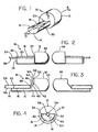
- a fiber alignment and retention apparatus referred to be the general reference character 10 and incorporating the present invention.
- the fiber alignment and retention apparatus 10 includes an optical lens 12, a holding means 14, a rearward extension 16, a longitudinally extending vee-shaped groove 18 symmetrically located in a top surface 20 of the rearward extention 16 and an interface 22 located between the optical lens 12 and the rearward extension 16.
- a side elevation of the fiber alignment and retention apparatus 10 shown in Fig. 2 includes a heat sensitive shrink sleeve 30, a forwardly directed curved lens surface 32, a first light transmitting optical fiber 34 for transmitting an optical signal 36 and a second light transmitting optical fiber 38.
- FIG. 3 includes an abutment means 40, a ramp section 42, a vertical fiber stop 44, a terminal end 46 of the first optical fiber 34 located at a focal point 48 of the optical lens 12, an abutment gap 50 located between a rearward portion 52 of the optical lens 12 and the terminal end 46 and an index of refraction matching adhesive 54 located within the abutment gap 50.
- An end view of the fiber alignment and retention apparatus 10 shown in Fig. 4 includes the heat sensitive shrink sleeve 30 which has an inner lining 56 comprised of the index of refraction matching adhesive 54.
- the first optical fiber 34 transmits the optical signal 36 to the optical lens 12 which is employed to expand the optical signal 36.
- the expansion of the optical signal 36 is required to permit the passage of light from the first optical fiber 3 4 having a first cross-sectional dimension to a second optical fiber 38 having a second cross-sectional dimension.
- the forwardly directed curved lens surface 32 is employed to direct the optical signal 36 to a second lens (not shown) or directly to the second optical fiber 38 having the second cross-sectional dimension.
- the lens 12 and the rearward extension 16 of the holding means 14 are molded together from a single piece of acrylic plastic material.
- the vee-shaped groove 18 is symmetrically located in the top surface 20 of the rearward extention 16 along the optical center of the lens 12.
- the rearward portion 52 of the lens 12 includes the ramp section 42 which causes the focal point 48 to be "in space” behind the lens 12 (shown in Fig. 3 ).
- the refraction and attenuation of the optical signal 36 is minimized by aligning the first optical fiber 34 with an imaginary plane passing through the focal point 48.
- the abutment means 40 is designed to position the terminal end 46 of the first optical fiber 34 at the focal point 48.
- the abutment means 40 includes the ramp section 42 with an angle of approximately forty-five degrees and the vertical fiber stop 44.
- the fiber stop 44 is located at the bottom of the ramp section 42 at the connection of the rearward extension 16 and within the imaginary plane passing through focal point 48 (see Fig. 3).
- the travel of the first optical fiber 34 is limited by the fiber stop 44 to properly align the terminal end 46.
- the ramp section 42 may be replaced by a radiused curved section 58 (shown dotted in Fig. 3) comprised of acrylic plastic and located between the rearward portion 52 of the lens 12 and the fiber stop 44.
- the fiber stop 44 is then located between the radius curved section 58 and the rearward extension 16 of the holding means 14.
- the abutment gap 50 is an air space created by the separation of the fiber stop 44 and the rearward portion 52 of lens 12 located above the ramp section 42.
- the gap 50 separates the first optical fiber 34 comprised of glass from the lens 12 comprised of plastic. If air occupies the gap 50, the attenuation of the optical signal 3 6 will be significant.
- the gap 50 is filled with the index matching adhesive 54 which has a refraction index similar to both glass and acrylic plastic.
- An example of the index matching adhesive 54 is one from a class of chemical compounds entitled cyano'acrylate which also exhibit bonding properties.
- the index matching adhesive 54 reduces refraction and attenuation during transmission of the optical signal 36 from the first optical fiber 34 to the lens 12.
- a retention means is in mechanical communication with the rearward extension 16 for securely retaining the first optical fiber 34 within the vee-shaped groove 18.
- the retention means comprises the heat sensitive shrink sleeve 30 which collapses about the rearward extension 16 upon being heat activated at a temperature of approximately 85 degrees centigrade.
- the acrylic plastic material of the lens 12 and of the holding means 14 are not damaged at this temperature.
- the inner lining 56 of the shrink sleeve 30 includes the index matching adhesive 54 which automatically bonds the first optical fiber 34 in position within the vee-shaped groove 1 8 upon application of the heat. Using this method, air is not trapped between the terminal end 46 of the first optical fiber 34 and the focal point 48.
- the tapered shape around the vee-shaped groove 18 permits the shrink sleeve 30 to force the first optical fiber 34 and the index matching adhesive 54 towards the lens 12 as the shrink sleeve 3 0 contracts.
- the terminal end 46 is forced toward the fiber stop 44 and the index matching adhesive 54 of the inner lining 56 is forced by the applied heat to flow into and fill the abutment gap 50.
- the index matching adhesive 54 solidifies at ambient temperature and provides attenuation reduction of the optical signal 36.
- the longitudinally extending vee-shaped groove 18 may be replaced by a longitudinally extending curved groove 60 (see Fig. 4) symmetrically located in the top surface 20 of the rearward extension 16 along the optical center of the lens 12.
- the first optical fiber 34 is guided into the vee-shaped groove 18 until the terminal end 46 of the first optical fiber 34 abuts the fiber stop 44.
- the shrink sleeve 30 is then wrapped about the rearward extension 16 and heat is applied to collapse the shrink sleeve 30 securing the first optical fiber 34 in the vee-shaped groove 18 and forcing the index matching adhesive 54 into the abutment gap 50.
- the terminal end 46 is then located at the focal point 48 of the lens 12 which ensures the reduction of refraction and attenuation of the optical signal 36.
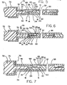
- FIG. 5 there is illustrated a cross-sectional view of an optical contact referred to by the general reference character 70 and incorporating the present invention.
- the optical contact 70 includes a plastic sheath 72, a buffer 74, an internal eyelet 76, an external eyelet 78 and an inspection hole 80.
- the optical contact 70 shown in Figs. 5 , 6 and 7 include each of the elements of the fiber alignment and retention apparatus 10 illustrated in Figs. 1-4 except the heat sensitive shrink sleeve 30.
- the heat sensitive shrink sleeve 30 is compatible and preferred in Figs. 5. 6 and 7.
- the first optical fiber 34 is protected by both the plastic sheath 72 and the buffer 74.
- the plastic sheath 72 is an outer layer or coating for providing protection of the first optical fiber 34 upon entry to the internal eyelet 76.
- the buffer 74 is an inner layer or coating for providing protection of the first optical fiber 3 4 between the interior of the plastic sheath 72 and a retention means.
- the buffer 74 is applied to the first optical fiber 34 via an extrusion process.
- the interior eyelet 76 which is comprised of metal is fitted and securely wrapped about the plastic sheath 72 and the buffer 7 4 for protecting the first optical fiber 34.
- the exterior eyelet 78 is also comprised of metal and is fitted and wrapped about a tapered end of the interior eyelet 76 and further is wrapped about the fiber alignment and retention apparatus 10.
- the exterior eyelet 78 also includes the inspection hole 80 located in the top surface thereof.
- the inspection hole 80 permits visual verification that the terminal end 46 abuts the vertical fiber stop 44.
- droplets of the index matching adhesive 54 are inserted in the abutment gap 50 through the inspection hole 80.
- the exterior eyelet 78 also functions to lock the retaining means in place in designs which do not employ the shrink sleeve 30.
- a mechanical clamp 86 is employed as the retention means.
- the mechanical clamp 86 utilizes a clamp finger 88 to secure the first optical fiber 34 within the vee-shaped groove 18 and against the fiber stop 44.
- the mechanical clamp 86 is fashioned from metal and is shaped to fit within the external eyelet 78 and abutted adjacent the tapered end of the internal eyelet 76.
- a passageway 90 is formed within the mechanical clamp 86 to encircle and secure the buffer 74 and to stabilize the first optical fiber 34 between the buffer 74 and the vee-shaped groove 18.
- the mechanical clamp 86 is held within the external eyelet 78 by a press-fit with the fiber alignment and retention apparatus 10 being pressed into position therebehind.
- a soft clamp 92 is employed as the retention means.
- the soft clamp 92 utilizes a soft finger 94 to secure the first optical fiber 34 within the vee-shaped groove 18 and against the fiber stop 44.
- the soft clamp 9 2 is fashioned from silicon foam and is shaped to fit within the external eyelet 78 and abutted adjacent the tapered end of the internal eyelet 76.
- a rear portion of the soft clamp 92 is circular and includes an opening 96 through which the first optical fiber 34 passes through.
- the optical fiber 34 is inserted within the soft clamp 92 and the optical lens 12 is forced under the soft finger 9 4 which forces the optical fiber 34 into the vee-shaped groove 18.
- the soft clamp 92 is held within the external eyelet 78 by a press-fit with the fiber alignment and retention apparatus 10 pressed in therebehind.
- a spring finger 98 is employed as the retention means.
- the spring finger 98 is fashioned from metal and is an extension of the internal eyelet 76 and is bounded by the external eyelet 78.
- the fiber alignment and retention apparatus 10 is forced into the external eyelet 78 and is secured by a press-fit.
- the spring finger 98 forces the first optical fiber 34 into the vee-shaped groove 18 and aligns the terminal end 46 with the focal point 48.
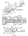
- FIG. 8 there is illustrated a first alternative embodiment of a fiber alignment and retention apparatus referred to by the general reference character 10 0 and incorporating the present invention.
- Those elements of embodiment 100 common to the fiber alignment and retention apparatus 10 of the preferred embodiment are designated with a single prime designation.
- the fiber alignment and retention apparatus 100 includes an optical lens 12' comprised of acrylic plastic, a holding means 14', a rearward extension 16', a longitudinally extending vee-shaped groove 18' symmetrically located in a top surface 20', a heat sensitive shrink sleeve 30', a forwardly directed curved lens surface 32', a first light transmitting I - optical fiber 34' for transmitting an optical signal 3 6' , a second light transmitting optical fiber 38', an abutment means 40', a ramp section 42', a vertical fiber stop 44', a terminal end 46' of the first optical fiber 34' located at a focal point 48' of the optical lens 12', an abutment gap 50' located between a rearward portion 52' of the optical lens 12' and the terminal end 46' and an index of refraction matching adhesive 54'.
- an optical lens 12' comprised of acrylic plastic
- a holding means 14' a rearward extension 16'
- the abutment means 40', ramp section 42', vertical fiber stop 44', terminal end 46 ', focal point 48', abutment gap 50' and index matching adhesive 54' are not visible in Fig. 8 but are duplicate to those of the preferred embodiment.
- the fiber alignment and retention apparatus 100 further includes a first half cylinder 102 and a second half cylinder 104 of the rearward extension 16', a first longitudinal cutaway 106 and a second longitudinal cutaway 108 of the second half cylinder 10 4 . and a shallow step 110 formed in an exterior surface 112 of the first half cylinder 102 and the second half cylinder 104 .
- the plastic optical lens 12' employs the forwardly directed curved lens surface 32' for reducing refraction and attenuation of the optical signal 36 1 when the optical signal 36' is transmitted from the first optical fiber 34' having a first dimension to the second optical fiber 38 ' having a second dimension.
- the holding means 14' which is molded to the optical lens 12' includes the rearward extension 16' which is cylindrically shaped.
- the cylindrical shaped rearward extension 16' includes the first half cylinder 102 and the second half cylinder 104.
- the vee-shaped groove 18' is symmetrically located in the top surface 20' of the first half cylinder 102 where the top surface 20' is positioned between the first half cylinder 102 and the second half cylinder 104.
- the vee-shaped groove 18' supports the first optical fiber 34' and the rearward extension 16' is molded to the optical lens 12' from a single piece of the plastic material.
- the second half cylinder 104 includes the first longitudinal cutaway 106 and the second longitudinal cutaway 108 which are each located between the second half cylinder 1 04 and the top surface 20' of the first half cylinder 102. Together, the first longitudinal cutaway 106 and the second longitudinal cutaway 108 of the second half cylinder 1 04 provide a spring tension on the first optical fiber 34' .
- the abutment means 40' is formed at the interface between the optical lens 12' and the top surface 20' for positioning the terminal end 46' of the first optical fiber 34' at the focal point 48' of the optical lens 12'.
- the abutment means 40 1 is formed from the single piece of plastic material and includes the ramp section 42' and the vertical stop 44 1 .
- the vertical stop 44' which positions the terminal end 46' is located where the ramp section 42' is connected to the top surface 20' of the first half cylinder 10 2 .
- the abutment gap 50' is disposed between the rearward portion 52' of the optical lens 12' and the terminal end 46' and above the ramp section 42 1.
- the index matching adhesive 54 1 is disposed within the abutment gap 50 1 .
- the retention means comprises the heat sensitive shrink sleeve 30' wrapped about the holding means 14' in the shallow step 110 formed in the exterior surface 112 of the first half cylinder 1 02 and the second half cylinder 104 for securely retaining the first optical fiber 34 1 within vee-shaped groove 18'.
- the shrink sleeve 30' in the first alternative embodiment does not include the inner lining 56 of the preferred embodiment because the shrink sleeve 30' of the first alternative embodiment does not contact the first optical fiber 34 ' .
- FIG. 9 there is illustrated an optical contact referred to by the general reference character 200 and incorporating a second alternative embodiment of a fiber alignment and retention apparatus of the present invention.
- Those elements of embodiment 200 common to the fiber alignment and retention apparatus 10 of the preferred embodiment are designated with a double prime designation.
- the optical contact 200 includes an optical lens 12" comprised of acrylic plastic, a holding means 14", a rearward extension 16", a longitudinally extending vee-shaped groove 18", a top surface 20", an interface 22", a forwardly directed curved lens surface 32", a first light transmitting optical fiber 34", an optical signal 36", a second light transmitting optical fiber 38", an abutment means 40", a vertical fiber stop 44", a terminal end 46".
- the fiber alignment and retention apparatus of the optical contact 200 further includes a rearwardly directed radiused surface 202 and a curved foot 204 located at a rearward end 206 of the rearward extension 16".
- the optical lens 12" in additional to having the forwardly directed curved lens 32" for reducing refraction and attenuation of the optical signal 36" also has the rearwardly directed radiused surface 202 which provides guidance to and retention of the first optical fiber 34".
- the holding means 14" is molded to the optical lens 32" and the first optical fiber 34" is inserted into the vee-shaped groove 18" located in the top surface 20" of the rearward extension 16".
- the rearward extension 16" also includes the rearward end 206 which is formed into the curved foot 204 which facilitates the entering and guiding of the first optical fiber 34" into the vee-shaped groove 18".
- the abutment means 40" is formed at the interface 22" of the optical lens 12" and the rearward extension 16" for positioning the terminal end 46" of the first optical fiber 34" at the focal point 48".
- the abutment means 40" is comprised of the single piece of plastic material in which is formed the vertical fiber stop 44" where the rearwardly directed radiused surface 202 is connected to the rearward extension 16".
- the abutment gap 50" is disposed between the rearwardly directed radiused surface 202 and the first optical fiber 34" and contains the index matching adhesive 54" .
- the abutment means 40" vertical fiber stop 44", terminal end 46", focal point 48", abutment gap 50" and index matching adhesive 54" are not visible in Fig. 9 but are duplicate to those of the preferred embodiment.
- the rearwardly directed radiused surface 202 is also employed as the retention means utilizing a press fit to secure the first optical fiber 34". Note that the first optical fiber 34" is guided into the vee-shaped groove 18" via the curved foot 2 04 and beneath the rearwardly directed radiused surface 202 which applies the press fit.
- the second alternative embodiment incorporated in the optical contact 200 does not utilize a shrink sleeve or a clamp and further the radiused surface 202 could also be any appropriate surface such as an angled surface.
- the inspection hole 80" through which the index matching adhesive 54" in inserted is located in the side of the optical contact 200 which permits visual verification that the terminal end 46" is abutting the vertical fiber stop 44" and the focal point 48" of optical lens 12".
Abstract
Description
- The invention relates generally to optical systems and more particularly to an optical contact for positioning and retaining an optical fiber with a lens.
- In the field of optical communications, optical fibers are employed to carry data from a transmitting station to a receiving station. In order to transmit an optical signal from a light source via a first optical fiber to another optical conducting element, e.g.. a second optical fiber of a different cross-sectional dimension, an optical lens is employed to redirect the light rays of the optical signal. Each optical fiber has an endface in which the optical signal must pass through. To prevent attenuation of the optical signal, the optical fiber endface must interface with the focal point along the optical axis of the lens.
- In the past. several techniques were utilized to align the optical fiber to the lens. Each of the techniques employed one of a plurality of lens contacts for terminating the optical fiber. A first of these techniques teaches that the lens contact is terminated by micropositioning a "pigtailed" optical fiber, that is, the fiber is back illuminated and optimized in position. The optimized position of the fiber is accomplished by projecting the back illumination of the fiber through the lens to a target on a screen. When the back illumination through the lens strikes the target on the screen, the fiber is bonded securely and thus optimized in position with the fiber endface interfacing the focal point of the lens. A second of these alignment techniques involves providing a cylindrical hole behind the lens. The cylindrical hole is aligned along the optical axis of the lens and is blind ended at the focal point of the lens. Also, the cylindrical hole has a diameter that accommodates the optical fiber with a close fit and the optical fiber is bonded within the cylindrical hole with an index of refraction matched adhesive.
- A problem associated with the first technique is the tedious requirement of adjusting the optical fiber to a stringent tolerance to permit the back illumination through the lens to strike the target. A second problem that exists in the second technique of alignment concerns a hydraulic effect that occurs when the fiber is inserted into the cylindrical hole. The index matched adhesive creates a hydraulic force that prevents the fiber endface from reaching the focal point of the lens, thus resulting in loss of light or attenuation of the optical signal.
- Several prior art references which are relevant to the instant invention have been discovered and will be discussed briefly.
- In Contina. British Patent 1.017.354. there is disclosed a system in which light is transmitted from one element to another so that the difference in cross-sections between the elements can be effected within a very short distance without loss of intensity. An optical system comprised of two bundles of optical fibers is arranged with one end of a first bundle facing one end of a second bundle and spaced apart therefrom. The ends of the two bundles are of different areas and a transparent body optically couples the two ends together. The transparent body has a reflecting surface which is substantially ellipsoidal in shape and coaxial with the bundle ends. Light rays of the optical signal are reflected such that they pass through a focal point in an axial endface of the second bundle.
- In Kahn, British Patent 1,429,843, there is disclosed a coupling unit consisting of a first housing member and a second housing member each carrying an end region of one of two light guides. The first housing member has a first coupling formed to fit into a second coupling of the second housing member. The first light guide is held centrally in the first coupling by a first body and the second light guide is held centrally in the second coupling by a second body. During manufacture, the ends of the light guides may be polished with the faces of the first and second bodies. A lens is mounted between the ends of the two light guides. Accurate alignment between the lens and the light guides is required.
- In Cook et al., United States Patent 3.950.075. there is disclosed an optical communication system which includes a diode for emitting optical wave energy to be coupled to an optical waveguide bundle. A transparent spherical bead is axially aligned with the bundle and the center of the light emitting area of the diode. The bead is securely mounted in an aperture which extends through one end of an insert within a housing. Precise alignment of the center of the bead along the axis of the aperture results from a force fit. The diode is disposed in the housing for proper alignment of the light emitting area of the diode with the bead. The end of the bundle is disposed in a termination ferrule having an aperture, the bundle being potted in the ferrule by a bonding material. The ferrule maintains the fiber bundle in a substantially parallel alignment. A problem is the high tolerance alignment required between the diode, the bead and the bundle.
- In Hunzinger. United States Patent 4.102.559. there is disclosed an optical structure comprising two very thick plano-convex lenses with a common axis. The convex surfaces of the lenses face each other while a radiation source and an input face of a fiber are each disposed on one of the convex surfaces in the vicinity of the axis. The main feature of the device resides in the considerable thickness of the lenses relative to the radii of curvature of the dioptric faces. As a result, aberrations, in particular spherical aberrations, are reduced while the dimensions of the device are such as to enable easy construction and handling.
- In Chown. United States Patent 4,147,402, there is disclosed a process for manufacturing a lens termination for an optical fiber using laser machining to form a cavity which centers the fiber in the termination. A plastic preform is provided comprising a tube member with a coaxial bore having one end closed by a lens at least the rearward portion of which comprises a plastic material. The bore and lens are arranged such that the base of the bore lies in the focal plane of the lens. Light is directed from a laser through the lens so as to focus the light onto the base of the bore thus evaporating a portion of the plastic material to form a cavity which, when the termination is in use, receives the bared end of a coated optical fiber. An index matching adhesive is used to bond the fiber within the cavity which produces the previously described hydraulic force preventing the fiber endface from reaching the focal plane of the lens.
- In Rush et al., United States Patent 4,183,618, there is disclosed an optical waveguide including a connector having a longitudinal bore in which an end of an optical waveguide is to be anchored, lens means for transmitting light from one end of the waveguide and defining a recess including a focal point of the lens means, and a housing in which the connector and lens means are mounted. The terminal also includes an elongate optical member having first and second ends with respective end faces, the first end of the elongate optical member extending partially through the connector and being anchored therein, and the second end of the elongate optical member being mounted in the recess in the lens means with its end face disposed at the focal point of the lens means. The connector includes means for maintaining the first end of the optical member and an end of an optical waveguide in alignment with one another.
- In Khoe et al., United States Patent 4,327,963. there is disclosed a coupling element for an optical transmission system having a coupling element comprised of a convex lens with a refractive index. The refractive index is dependent on a radius "r" of a shell in the lens. The coupling element further includes a holder through which a capillary extends. The convex lens which is spherical is affixed to an end of an optical fiber with the lens-fiber interface being enclosed within the capillary. The capillary is preferably circular cylindrical in shape and may rest in a v-shaped groove of a holder. A transparent coupling medium may be disposed between the lens and the fiber for light refraction purposes.
- Further, the prior art discloses a hermaphroditic rugged optical fiber connector which uses fibres terminated with miniature lenses and intended for use under adverse field conditions. A microlens is positioned on the end of each fiber to form an expanded beam termination which reduces the effect of dirt on the connector performance and provides easy cleaning. Two expanded beam terminations are housed in the rear insert, with a cable strength member clamp, which has a high tensile performance, and are located in a precision front insert in the connector body. A cable end and a plurality of fiber terminations are protected from the environment by being sealed in the connector body cavity. A replaceable protective window forms the cavity seal at the front of the connector whilst an O-ring in the endbell nut seals the cable entry.
- After consideration of the known prior art relevant to the instant invention, the problems involving tedious alignment adjustments and the hydraulic effect resulting in optical signal attenuation still exist.
- It is therefore an object of the present invention to provide an improved fiber alignment and retention apparatus capable of accurately aligning an optical fiber with lower tolerance measurements.
- It is a further object to provide an improved fiber alignment and retention apparatus capable of inexpensively retaining the aligned fiber position.
- Briefly, a preferred embodiment of the present invention includes an optical lens having a forwardly directed curved lens surface and a holding means having a rearward extension with a longitudinally extending vee-shaped groove for supporting a first light transmitting optical fiber. The lens and rearward extension are fashioned from a single piece of plastic material with an abutment means comprised of a ramp section including a vertical stop at an interface therebetween. A focal point of the lens is located in a vertical plane of the vertical stop and an abutment gap is formed between a rearward portion of the lens and the vertical stop. A heat sensitive shrink sleeve acts as a retention means for securing the optical fiber within the vee-shaped groove. The shrink sleeve includes an inner lining comprised of an index matching adhesive material.
- The first light transmitting optical fiber is guided into the vee-shaped groove until a terminal end of the fiber abuts the fiber stop. The shrink sleeve is then wrapped about the rearward extension and heat shrunk to secure the fiber in the vee-shaped groove. The terminal end is located at the focal point of the lens which ensures the reduction of refraction and attenuation of an optical signal between the first light transmitting optical fiber and a second light transmitting optical fiber.
- The preferred embodiment may also be practiced by eliminating the shrink sleeve and substituting therefor a metal mechanical clamp, a silicon foam clamp or a spring finger as the retention means.
- A first alternative embodiment of the present invention includes an optical lens having a forwardly directed curved lens surface and a holding means molded to the lens including a cylindrical shaped rearward extension having a first half cylinder and a second half cylinder. A longitudinally extending vee-shaped groove is symmetrically located in a top surface of the first half cylinder between the first and second half cylinders. The second half cylinder includes a first and a second longitudinal cutaway section which provides a spring tension between the first and second half cylinders. An abutment means is provided at an interface between the first half cylinder and the lens for positioning a terminal end of a first light transmitting optical fiber at a focal point of the lens. The abutment means comprises a ramp section and a vertical stop which form an abutment gap which contains an index matching adhesive. A heat sensitive shrink sleeve is wrapped about the cylindrical shaped rearward extension for retaining the first optical fiber within the vee-shaped groove.
- A second alternative embodiment of the present invention includes an optical lens having a forwardly directed curved lens surface and a rearwardly directed radiused surface. A holding means is connected to the lens and has a rearward extension with a longitudinally extending vee-shaped groove and a curved foot located at a rearward end of the rearward extension. An abutment means includes a vertical stop for positioning a terminal end of an optical fiber and an abutment gap which contains an index matching adhesive. When the optical fiber is inserted into the vee-shaped groove, the curved foot guides the fiber while the rearwardly directed radiused surface guides and retains the fiber in position.
- An advantage of the fiber alignment and retention apparatus of the present invention is that the optical fiber may be accurately aligned with lower tolerance measurements.
- Another advantage is that the fiber alignment and retention apparatus inexpensively retains the aligned fiber position.
- These and other objects and advantages of the present invention will no doubt become obvious to those of ordinary skill in the art after having read the following detailed description of the preferred embodiment(s) which are illustrated in the various drawing figures.
- Fig. 1 is a perspective view of a fiber alignment and retention apparatus in accordance with the present invention:
- Fig. 2 is a side elevational view of the fiber alignment and retention apparatus of Fig. 1 illustrating a first retention means;
- Fig. 3 is a side elevational view of the fiber alignment and retention apparatus of Fig. 1 illustrating an abutment means:
- Fig. 4 is an end view of the fiber alignment and retention apparatus of Fig. 1 illustrating the first retention means:
- Fig. 5 is a cross-sectional view of an optical contact illustrating a second retention means for the fiber alignment and retention apparatus taken along the line 5-5 of Fig. 1;
- Fig. 6 is a cross-sectional view of an optical contact illustrating a third retention means for the fiber alignment and retention apparatus of Fig. 1;
- Fig. 7 is a cross-sectional view of an optical contact illustrating a fourth retention means for the fiber alignment and retention apparatus of Fig. 1;
- Fig. 8 is a perspective view of a first alternative embodiment of a fiber alignment and retention apparatus of the present invention: and
- Fig. 9 is a cross-sectional view of a second alternative embodiment of a fiber alignment and retention apparatus of the present invention.
- In Fig. 1. there is illustrated a fiber alignment and retention apparatus referred to be the
general reference character 10 and incorporating the present invention.. The fiber alignment andretention apparatus 10 includes anoptical lens 12, a holding means 14, arearward extension 16, a longitudinally extending vee-shapedgroove 18 symmetrically located in atop surface 20 of therearward extention 16 and aninterface 22 located between theoptical lens 12 and therearward extension 16. A side elevation of the fiber alignment andretention apparatus 10 shown in Fig. 2 includes a heatsensitive shrink sleeve 30, a forwardly directedcurved lens surface 32, a first light transmittingoptical fiber 34 for transmitting anoptical signal 36 and a second light transmittingoptical fiber 38. Another side elevation of the fiber alignment andretention apparatus 10 shown in Fig. 3 includes an abutment means 40, aramp section 42, avertical fiber stop 44, aterminal end 46 of the firstoptical fiber 34 located at afocal point 48 of theoptical lens 12, anabutment gap 50 located between arearward portion 52 of theoptical lens 12 and theterminal end 46 and an index ofrefraction matching adhesive 54 located within theabutment gap 50. An end view of the fiber alignment andretention apparatus 10 shown in Fig. 4 includes the heatsensitive shrink sleeve 30 which has aninner lining 56 comprised of the index ofrefraction matching adhesive 54. - In the instant invention, the first
optical fiber 34 transmits theoptical signal 36 to theoptical lens 12 which is employed to expand theoptical signal 36. The expansion of theoptical signal 36 is required to permit the passage of light from the first optical fiber 34 having a first cross-sectional dimension to a secondoptical fiber 38 having a second cross-sectional dimension. The forwardly directedcurved lens surface 32 is employed to direct theoptical signal 36 to a second lens (not shown) or directly to the secondoptical fiber 38 having the second cross-sectional dimension. Thelens 12 and therearward extension 16 of the holding means 14 are molded together from a single piece of acrylic plastic material. The vee-shapedgroove 18 is symmetrically located in thetop surface 20 of therearward extention 16 along the optical center of thelens 12. Therearward portion 52 of thelens 12 includes theramp section 42 which causes thefocal point 48 to be "in space" behind the lens 12 (shown in Fig. 3). The refraction and attenuation of theoptical signal 36 is minimized by aligning the firstoptical fiber 34 with an imaginary plane passing through thefocal point 48. The abutment means 40 is designed to position theterminal end 46 of the firstoptical fiber 34 at thefocal point 48. Formed from the single piece of acrylic plastic, the abutment means 40 includes theramp section 42 with an angle of approximately forty-five degrees and thevertical fiber stop 44. Thefiber stop 44 is located at the bottom of theramp section 42 at the connection of therearward extension 16 and within the imaginary plane passing through focal point 48 (see Fig. 3). The travel of the firstoptical fiber 34 is limited by thefiber stop 44 to properly align theterminal end 46. Note that theramp section 42 may be replaced by a radiused curved section 58 (shown dotted in Fig. 3) comprised of acrylic plastic and located between therearward portion 52 of thelens 12 and thefiber stop 44. Thefiber stop 44 is then located between the radius curvedsection 58 and therearward extension 16 of the holding means 14. Theabutment gap 50 is an air space created by the separation of thefiber stop 44 and therearward portion 52 oflens 12 located above theramp section 42. Thegap 50 separates the firstoptical fiber 34 comprised of glass from thelens 12 comprised of plastic. If air occupies thegap 50, the attenuation of the optical signal 36 will be significant. To avoid high attenuation of theoptical signal 36, thegap 50 is filled with the index matching adhesive 54 which has a refraction index similar to both glass and acrylic plastic. An example of theindex matching adhesive 54 is one from a class of chemical compounds entitled cyano'acrylate which also exhibit bonding properties. Theindex matching adhesive 54 reduces refraction and attenuation during transmission of theoptical signal 36 from the firstoptical fiber 34 to thelens 12. A retention means is in mechanical communication with therearward extension 16 for securely retaining the firstoptical fiber 34 within the vee-shapedgroove 18. In the preferred embodiment, the retention means comprises the heatsensitive shrink sleeve 30 which collapses about therearward extension 16 upon being heat activated at a temperature of approximately 85 degrees centigrade. The acrylic plastic material of thelens 12 and of the holding means 14 are not damaged at this temperature. Theinner lining 56 of theshrink sleeve 30 includes the index matching adhesive 54 which automatically bonds the firstoptical fiber 34 in position within the vee-shaped groove 18 upon application of the heat. Using this method, air is not trapped between theterminal end 46 of the firstoptical fiber 34 and thefocal point 48. The tapered shape around the vee-shapedgroove 18 permits theshrink sleeve 30 to force the firstoptical fiber 34 and the index matching adhesive 54 towards thelens 12 as theshrink sleeve 30 contracts. Theterminal end 46 is forced toward thefiber stop 44 and theindex matching adhesive 54 of theinner lining 56 is forced by the applied heat to flow into and fill theabutment gap 50. Theindex matching adhesive 54 solidifies at ambient temperature and provides attenuation reduction of theoptical signal 36. Note that the longitudinally extending vee-shapedgroove 18 may be replaced by a longitudinally extending curved groove 60 (see Fig. 4) symmetrically located in thetop surface 20 of therearward extension 16 along the optical center of thelens 12. - In practice, the first
optical fiber 34 is guided into the vee-shapedgroove 18 until the terminal end 46 of the firstoptical fiber 34 abuts thefiber stop 44. Theshrink sleeve 30 is then wrapped about therearward extension 16 and heat is applied to collapse theshrink sleeve 30 securing the firstoptical fiber 34 in the vee-shapedgroove 18 and forcing the index matching adhesive 54 into theabutment gap 50. Theterminal end 46 is then located at thefocal point 48 of thelens 12 which ensures the reduction of refraction and attenuation of theoptical signal 36. - In each of the Figs. 5, 6 and 7 there is illustrated a cross-sectional view of an optical contact referred to by the
general reference character 70 and incorporating the present invention. Each of the Figs. 5, 6 and 7 incorporate the fiber alignment andretention apparatus 10 while illustrating alternative retention means to the preferred embodiment. Theoptical contact 70 includes aplastic sheath 72, abuffer 74, aninternal eyelet 76, anexternal eyelet 78 and aninspection hole 80. Additionally, theoptical contact 70 shown in Figs. 5, 6 and 7 include each of the elements of the fiber alignment andretention apparatus 10 illustrated in Figs. 1-4 except the heatsensitive shrink sleeve 30. However, the heatsensitive shrink sleeve 30 is compatible and preferred in Figs. 5. 6 and 7. The firstoptical fiber 34 is protected by both theplastic sheath 72 and thebuffer 74. Theplastic sheath 72 is an outer layer or coating for providing protection of the firstoptical fiber 34 upon entry to theinternal eyelet 76. Thebuffer 74 is an inner layer or coating for providing protection of the first optical fiber 34 between the interior of theplastic sheath 72 and a retention means. Thebuffer 74 is applied to the firstoptical fiber 34 via an extrusion process. Theinterior eyelet 76 which is comprised of metal is fitted and securely wrapped about theplastic sheath 72 and the buffer 74 for protecting the firstoptical fiber 34. Theexterior eyelet 78 is also comprised of metal and is fitted and wrapped about a tapered end of theinterior eyelet 76 and further is wrapped about the fiber alignment andretention apparatus 10. Theexterior eyelet 78 also includes theinspection hole 80 located in the top surface thereof. Theinspection hole 80 permits visual verification that theterminal end 46 abuts thevertical fiber stop 44. In the designs of theoptical contact 70 which employ a retaining means other than the heatsensitive shrink sleeve 30, droplets of theindex matching adhesive 54 are inserted in theabutment gap 50 through theinspection hole 80. Theexterior eyelet 78 also functions to lock the retaining means in place in designs which do not employ theshrink sleeve 30. - In Fig. 5, a
mechanical clamp 86 is employed as the retention means. Themechanical clamp 86 utilizes aclamp finger 88 to secure the firstoptical fiber 34 within the vee-shapedgroove 18 and against thefiber stop 44. Note that themechanical clamp 86 is fashioned from metal and is shaped to fit within theexternal eyelet 78 and abutted adjacent the tapered end of theinternal eyelet 76. Apassageway 90 is formed within themechanical clamp 86 to encircle and secure thebuffer 74 and to stabilize the firstoptical fiber 34 between thebuffer 74 and the vee-shapedgroove 18. Themechanical clamp 86 is held within theexternal eyelet 78 by a press-fit with the fiber alignment andretention apparatus 10 being pressed into position therebehind. - In Fig. 6, a
soft clamp 92 is employed as the retention means. Thesoft clamp 92 utilizes asoft finger 94 to secure the firstoptical fiber 34 within the vee-shapedgroove 18 and against thefiber stop 44. The soft clamp 92 is fashioned from silicon foam and is shaped to fit within theexternal eyelet 78 and abutted adjacent the tapered end of theinternal eyelet 76. A rear portion of thesoft clamp 92 is circular and includes an opening 96 through which the firstoptical fiber 34 passes through. Theoptical fiber 34 is inserted within thesoft clamp 92 and theoptical lens 12 is forced under the soft finger 94 which forces theoptical fiber 34 into the vee-shapedgroove 18. Thesoft clamp 92 is held within theexternal eyelet 78 by a press-fit with the fiber alignment andretention apparatus 10 pressed in therebehind. - In Fig. 7, a
spring finger 98 is employed as the retention means. Thespring finger 98 is fashioned from metal and is an extension of theinternal eyelet 76 and is bounded by theexternal eyelet 78. The fiber alignment andretention apparatus 10 is forced into theexternal eyelet 78 and is secured by a press-fit. Thespring finger 98 forces the firstoptical fiber 34 into the vee-shapedgroove 18 and aligns theterminal end 46 with thefocal point 48. - In Fig. 8, there is illustrated a first alternative embodiment of a fiber alignment and retention apparatus referred to by the
general reference character 100 and incorporating the present invention. Those elements ofembodiment 100 common to the fiber alignment andretention apparatus 10 of the preferred embodiment are designated with a single prime designation. The fiber alignment andretention apparatus 100 includes an optical lens 12' comprised of acrylic plastic, a holding means 14', a rearward extension 16', a longitudinally extending vee-shaped groove 18' symmetrically located in a top surface 20', a heat sensitive shrink sleeve 30', a forwardly directed curved lens surface 32', a first light transmitting I- optical fiber 34' for transmitting an optical signal 36', a second light transmitting optical fiber 38', an abutment means 40', a ramp section 42', a vertical fiber stop 44', a terminal end 46' of the first optical fiber 34' located at a focal point 48' of the optical lens 12', an abutment gap 50' located between a rearward portion 52' of the optical lens 12' and the terminal end 46' and an index of refraction matching adhesive 54'. The abutment means 40', ramp section 42', vertical fiber stop 44', terminal end 46', focal point 48', abutment gap 50' and index matching adhesive 54' are not visible in Fig. 8 but are duplicate to those of the preferred embodiment. The fiber alignment andretention apparatus 100 further includes afirst half cylinder 102 and asecond half cylinder 104 of the rearward extension 16', a firstlongitudinal cutaway 106 and a secondlongitudinal cutaway 108 of thesecond half cylinder 104. and ashallow step 110 formed in anexterior surface 112 of thefirst half cylinder 102 and the second half cylinder 104. - The plastic optical lens 12' employs the forwardly directed curved lens surface 32' for reducing refraction and attenuation of the
optical signal 361 when the optical signal 36' is transmitted from the first optical fiber 34' having a first dimension to the secondoptical fiber 38' having a second dimension. The holding means 14' which is molded to the optical lens 12' includes the rearward extension 16' which is cylindrically shaped. The cylindrical shaped rearward extension 16' includes thefirst half cylinder 102 and thesecond half cylinder 104. The vee-shaped groove 18' is symmetrically located in the top surface 20' of thefirst half cylinder 102 where the top surface 20' is positioned between thefirst half cylinder 102 and thesecond half cylinder 104. The vee-shaped groove 18' supports the first optical fiber 34' and the rearward extension 16' is molded to the optical lens 12' from a single piece of the plastic material. Thesecond half cylinder 104 includes the firstlongitudinal cutaway 106 and the secondlongitudinal cutaway 108 which are each located between the second half cylinder 104 and the top surface 20' of thefirst half cylinder 102. Together, the firstlongitudinal cutaway 106 and the secondlongitudinal cutaway 108 of the second half cylinder 104 provide a spring tension on the first optical fiber 34'. The abutment means 40' is formed at the interface between the optical lens 12' and the top surface 20' for positioning the terminal end 46' of the first optical fiber 34' at the focal point 48' of the optical lens 12'. The abutment means 401 is formed from the single piece of plastic material and includes the ramp section 42' and thevertical stop 441. The vertical stop 44' which positions the terminal end 46' is located where the ramp section 42' is connected to the top surface 20' of thefirst half cylinder 102. The abutment gap 50' is disposed between the rearward portion 52' of the optical lens 12' and the terminal end 46' and above theramp section 421. Theindex matching adhesive 541 is disposed within theabutment gap 501. The retention means comprises the heat sensitive shrink sleeve 30' wrapped about the holding means 14' in theshallow step 110 formed in theexterior surface 112 of the first half cylinder 102 and thesecond half cylinder 104 for securely retaining the firstoptical fiber 341 within vee-shaped groove 18'. The shrink sleeve 30' in the first alternative embodiment does not include theinner lining 56 of the preferred embodiment because the shrink sleeve 30' of the first alternative embodiment does not contact the firstoptical fiber 34'. - In Fig. 9, there is illustrated an optical contact referred to by the
general reference character 200 and incorporating a second alternative embodiment of a fiber alignment and retention apparatus of the present invention. Those elements ofembodiment 200 common to the fiber alignment andretention apparatus 10 of the preferred embodiment are designated with a double prime designation. Theoptical contact 200 includes anoptical lens 12" comprised of acrylic plastic, a holding means 14", arearward extension 16", a longitudinally extending vee-shapedgroove 18", atop surface 20", aninterface 22", a forwardly directedcurved lens surface 32", a first light transmittingoptical fiber 34", anoptical signal 36", a second light transmittingoptical fiber 38", an abutment means 40", avertical fiber stop 44", aterminal end 46". afocal point 48", anabutment gap 50" and an index ofrefraction matching adhesive 54". Also shown is aplastic sheath 72", abuffer 74", aninternal eyelet 76". anexternal eyelet 78" and aside inspection hole 80" of theoptical contact 200. The fiber alignment and retention apparatus of theoptical contact 200 further includes a rearwardly directedradiused surface 202 and acurved foot 204 located at arearward end 206 of therearward extension 16". - The
optical lens 12" in additional to having the forwardly directedcurved lens 32" for reducing refraction and attenuation of theoptical signal 36" also has the rearwardly directed radiusedsurface 202 which provides guidance to and retention of the firstoptical fiber 34". The holding means 14" is molded to theoptical lens 32" and the firstoptical fiber 34" is inserted into the vee-shapedgroove 18" located in thetop surface 20" of therearward extension 16". Therearward extension 16" also includes therearward end 206 which is formed into thecurved foot 204 which facilitates the entering and guiding of the firstoptical fiber 34" into the vee-shapedgroove 18". The abutment means 40" is formed at theinterface 22" of theoptical lens 12" and therearward extension 16" for positioning theterminal end 46" of the firstoptical fiber 34" at thefocal point 48". The abutment means 40" is comprised of the single piece of plastic material in which is formed thevertical fiber stop 44" where the rearwardly directed radiusedsurface 202 is connected to therearward extension 16". Theabutment gap 50" is disposed between the rearwardly directed radiusedsurface 202 and the firstoptical fiber 34" and contains the index matching adhesive 54". The abutment means 40".vertical fiber stop 44",terminal end 46",focal point 48",abutment gap 50" and index matching adhesive 54" are not visible in Fig. 9 but are duplicate to those of the preferred embodiment. The rearwardly directed radiusedsurface 202 is also employed as the retention means utilizing a press fit to secure the firstoptical fiber 34". Note that the firstoptical fiber 34" is guided into the vee-shapedgroove 18" via the curved foot 204 and beneath the rearwardly directed radiusedsurface 202 which applies the press fit. The second alternative embodiment incorporated in theoptical contact 200 does not utilize a shrink sleeve or a clamp and further theradiused surface 202 could also be any appropriate surface such as an angled surface. Theinspection hole 80" through which the index matching adhesive 54" in inserted is located in the side of theoptical contact 200 which permits visual verification that theterminal end 46" is abutting thevertical fiber stop 44" and thefocal point 48" ofoptical lens 12". - Although the present invention has been described in terms of the presently preferred embodiment(s), it is to be understood that such disclosure is not to be interpreted as limiting. Various alterations and modifications will ho doubt become apparent to those skilled in the art after having read the above disclosure. Accordingly, it is intended that the appended claims be interpreted as covering all alterations and modifications as fall within the true spirit and scope of the invention.
Claims (18)
Applications Claiming Priority (2)
| Application Number | Priority Date | Filing Date | Title |
|---|---|---|---|
| US06/689,637 US4666238A (en) | 1985-01-07 | 1985-01-07 | Optical fiber alignment and retention device |
| US689637 | 1985-01-07 |
Publications (2)
| Publication Number | Publication Date |
|---|---|
| EP0188392A2 true EP0188392A2 (en) | 1986-07-23 |
| EP0188392A3 EP0188392A3 (en) | 1987-11-19 |
Family
ID=24769309
Family Applications (1)
| Application Number | Title | Priority Date | Filing Date |
|---|---|---|---|
| EP86400013A Withdrawn EP0188392A3 (en) | 1985-01-07 | 1986-01-06 | Optical fiber alignment and retention device |
Country Status (4)
| Country | Link |
|---|---|
| US (1) | US4666238A (en) |
| EP (1) | EP0188392A3 (en) |
| JP (1) | JPS61163306A (en) |
| CA (1) | CA1278205C (en) |
Cited By (10)
| Publication number | Priority date | Publication date | Assignee | Title |
|---|---|---|---|---|
| EP0195710A2 (en) * | 1985-03-11 | 1986-09-24 | Itt Industries, Inc. | An alignment and retention device for optical transmission fibers |
| US5015062A (en) * | 1988-12-02 | 1991-05-14 | Siemens Aktiengesellschaft | Splice union for the mechanical joining of two light waveguides |
| EP0485426A1 (en) * | 1989-08-02 | 1992-05-20 | E.I. Du Pont De Nemours And Company | Opto-electronic component having a positioned optical fiber associated therewith |
| EP0485415A1 (en) * | 1989-08-02 | 1992-05-20 | E.I. Du Pont De Nemours And Company | Apparatus for positioning the center of an optical fiber along a predetermined reference axis |
| US5243673A (en) * | 1989-08-02 | 1993-09-07 | E. I. Du Pont De Nemours And Company | Opto-electronic component having positioned optical fiber associated therewith |
| GB2286899A (en) * | 1994-02-28 | 1995-08-30 | Eev Ltd | Plano-convex lens for an optical fibre |
| WO2014039323A1 (en) * | 2012-09-04 | 2014-03-13 | Ninepoint Medical, Inc. | A low cost molded optical probe with astigmatic correction, fiber port, low back reflection, and highly reproducible in manufacturing quantities |
| WO2014142789A1 (en) * | 2013-03-11 | 2014-09-18 | Lightlab Imaging, Inc. | Optical fiber beam directing systems and apparatuses |
| EP2549313B1 (en) * | 2011-07-20 | 2020-07-01 | CommScope Connectivity Belgium BVBA | Ferrule with integrated fiber alignment |
| US11262511B2 (en) | 2012-02-07 | 2022-03-01 | Commscope Technologies Llc | Optical fiber connection system including optical fiber alignment device |
Families Citing this family (19)
| Publication number | Priority date | Publication date | Assignee | Title |
|---|---|---|---|---|
| US4968109A (en) * | 1984-04-19 | 1990-11-06 | E. I. Du Pont De Nemours And Company | Press bonding apparatus method for terminating an optical fiber with a plastically deformable termination member |
| DE4206011C1 (en) * | 1992-02-27 | 1993-04-08 | Ant Nachrichtentechnik Gmbh, 7150 Backnang, De | Collimator for light-wave conductor - consists of cylindrical body with lens surface on one face and staged blind bore on other |
| WO1995029422A1 (en) * | 1994-04-22 | 1995-11-02 | Omron Corporation | Optical fiber connecting structure, optical switch and optical connector |
| JP3124465B2 (en) * | 1995-01-13 | 2001-01-15 | 株式会社精工技研 | Optical coupler |
| WO2010019800A1 (en) * | 2008-08-13 | 2010-02-18 | Nomir Medical Technologies, Inc. | Therapeutic light delivery apparatus, method, and system |
| JP2004177937A (en) * | 2002-11-11 | 2004-06-24 | Yazaki Corp | Ferrule and optical coupling structure |
| JP2004246279A (en) * | 2003-02-17 | 2004-09-02 | Seiko Epson Corp | Optical module and its manufacturing method, optical communication device, optical and electric mixed integrated circuit, circuit board, electronic equipment |
| US7455462B2 (en) * | 2004-08-20 | 2008-11-25 | Avago Technologies Fiber Ip (Singapore) Pte. Ltd. | Zone two fiber optic cable |
| CA2603338A1 (en) * | 2005-04-04 | 2006-10-12 | Molex Incorporated | Multifiber mt-type connector and ferrule comprising v-groove lens array and method of manufacture |
| JP2008151843A (en) * | 2006-12-14 | 2008-07-03 | Omron Corp | Optical component for optical transmission and method of manufacturing same |
| JP4758368B2 (en) * | 2007-02-15 | 2011-08-24 | 株式会社巴川製紙所 | Optical terminator and manufacturing method thereof |
| JP2010204329A (en) * | 2009-03-03 | 2010-09-16 | Sae Magnetics (Hk) Ltd | Optical module |
| CN102798936B (en) * | 2011-05-23 | 2016-05-04 | 鸿富锦精密工业(深圳)有限公司 | Optical-fiber coupling connector |
| CN103827711B (en) | 2011-09-26 | 2017-06-09 | 3M创新有限公司 | Optical conenctor with a plurality of optical fiber that staggeredly cut end is coupled to relevant microlenses |
| US9207413B2 (en) | 2011-09-26 | 2015-12-08 | 3M Innovative Properties Company | Optical substrate having a plurality of staggered light redirecting features on a major surface thereof |
| US9435963B2 (en) * | 2012-03-30 | 2016-09-06 | Corning Cable Systems Llc | Misalignment-tolerant total-internal-reflection fiber optic interface modules and assemblies with high coupling efficiency |
| US9817187B2 (en) * | 2013-09-06 | 2017-11-14 | Afl Telecommunications Llc | End cap holder |
| EP4111951A1 (en) * | 2017-10-02 | 2023-01-04 | Lightlab Imaging, Inc. | Intravascular data collection probes and related assemblies |
| JP6886432B2 (en) * | 2018-07-06 | 2021-06-16 | ライトラボ・イメージング・インコーポレーテッド | Fiber Optic Beam Directional Systems and Equipment |
Citations (3)
| Publication number | Priority date | Publication date | Assignee | Title |
|---|---|---|---|---|
| US4129932A (en) * | 1977-11-14 | 1978-12-19 | Thomas & Betts Corporation | Method and means for joining elongate members |
| US4290667A (en) * | 1976-02-03 | 1981-09-22 | International Standard Electric Corporation | Optical fibre terminations and connectors |
| JPS58205107A (en) * | 1982-05-26 | 1983-11-30 | Nippon Sheet Glass Co Ltd | Lens with v-shaped groove base |
Family Cites Families (9)
| Publication number | Priority date | Publication date | Assignee | Title |
|---|---|---|---|---|
| US4078852A (en) * | 1976-09-13 | 1978-03-14 | The United States Of America As Represented By The Secretary Of The Navy | Radiant energy coupler |
| US4196032A (en) * | 1978-03-22 | 1980-04-01 | Essex Group, Inc. | Splice for optical ribbon having elongated strain relief elements in the ribbon and method of splicing the same |
| JPS54151047A (en) * | 1978-05-19 | 1979-11-27 | Nec Corp | Optical connector |
| US4421383A (en) * | 1980-01-17 | 1983-12-20 | Gte Laboratories Incorporated | Optical fiber connectors |
| JPS5776509A (en) * | 1980-10-30 | 1982-05-13 | Nippon Sheet Glass Co Ltd | Optical fiber-lens coupler and its manufacture |
| JPS57124321A (en) * | 1980-12-03 | 1982-08-03 | Combined Optical Ind Ltd | Fiber optical connector and lens element thereof |
| SE8202359L (en) * | 1981-04-20 | 1982-10-21 | Malco | DEVICE FOR INBOARD DIRECTION OF AN OPTICAL FIBER AND A COLLIMATOR LENS |
| US4534616A (en) * | 1982-05-24 | 1985-08-13 | Amp Incorporated | Fiber optic connector having lens |
| JPS6028708A (en) * | 1983-07-26 | 1985-02-13 | 住友電気工業株式会社 | Method of connecting lead theath of factory via long cable |
-
1985
- 1985-01-07 US US06/689,637 patent/US4666238A/en not_active Expired - Fee Related
- 1985-11-22 JP JP60263612A patent/JPS61163306A/en active Pending
- 1985-12-31 CA CA000498816A patent/CA1278205C/en not_active Expired - Fee Related
-
1986
- 1986-01-06 EP EP86400013A patent/EP0188392A3/en not_active Withdrawn
Patent Citations (3)
| Publication number | Priority date | Publication date | Assignee | Title |
|---|---|---|---|---|
| US4290667A (en) * | 1976-02-03 | 1981-09-22 | International Standard Electric Corporation | Optical fibre terminations and connectors |
| US4129932A (en) * | 1977-11-14 | 1978-12-19 | Thomas & Betts Corporation | Method and means for joining elongate members |
| JPS58205107A (en) * | 1982-05-26 | 1983-11-30 | Nippon Sheet Glass Co Ltd | Lens with v-shaped groove base |
Non-Patent Citations (1)
| Title |
|---|
| PATENT ABSTRACTS OF JAPAN, vol. 8, no. 55 (P-260)[1492], 13th March 1984; & JP-A-58 205 107 (NIHON ITA GLASS K.K.) 30-11-1983 * |
Cited By (15)
| Publication number | Priority date | Publication date | Assignee | Title |
|---|---|---|---|---|
| EP0195710A2 (en) * | 1985-03-11 | 1986-09-24 | Itt Industries, Inc. | An alignment and retention device for optical transmission fibers |
| EP0195710A3 (en) * | 1985-03-11 | 1988-09-14 | Itt Industries, Inc. | An alignment and retention device for optical transmission fibers |
| US5015062A (en) * | 1988-12-02 | 1991-05-14 | Siemens Aktiengesellschaft | Splice union for the mechanical joining of two light waveguides |
| EP0485426A4 (en) * | 1989-08-02 | 1992-09-16 | E.I. Du Pont De Nemours And Company | Opto-electronic component having a positioned optical fiber associated therewith |
| EP0485415A1 (en) * | 1989-08-02 | 1992-05-20 | E.I. Du Pont De Nemours And Company | Apparatus for positioning the center of an optical fiber along a predetermined reference axis |
| EP0485415A4 (en) * | 1989-08-02 | 1992-09-02 | E.I. Du Pont De Nemours And Company | Apparatus for positioning the center of an optical fiber along a predetermined reference axis |
| EP0485426A1 (en) * | 1989-08-02 | 1992-05-20 | E.I. Du Pont De Nemours And Company | Opto-electronic component having a positioned optical fiber associated therewith |
| US5243673A (en) * | 1989-08-02 | 1993-09-07 | E. I. Du Pont De Nemours And Company | Opto-electronic component having positioned optical fiber associated therewith |
| GB2286899A (en) * | 1994-02-28 | 1995-08-30 | Eev Ltd | Plano-convex lens for an optical fibre |
| EP2549313B1 (en) * | 2011-07-20 | 2020-07-01 | CommScope Connectivity Belgium BVBA | Ferrule with integrated fiber alignment |
| US11262511B2 (en) | 2012-02-07 | 2022-03-01 | Commscope Technologies Llc | Optical fiber connection system including optical fiber alignment device |
| US11892689B2 (en) | 2012-02-07 | 2024-02-06 | Commscope Technologies Llc | Optical fiber connection system including optical fiber alignment device |
| WO2014039323A1 (en) * | 2012-09-04 | 2014-03-13 | Ninepoint Medical, Inc. | A low cost molded optical probe with astigmatic correction, fiber port, low back reflection, and highly reproducible in manufacturing quantities |
| WO2014142789A1 (en) * | 2013-03-11 | 2014-09-18 | Lightlab Imaging, Inc. | Optical fiber beam directing systems and apparatuses |
| JP2016512616A (en) * | 2013-03-11 | 2016-04-28 | ライトラボ・イメージング・インコーポレーテッド | Optical fiber beam directing system and apparatus |
Also Published As
| Publication number | Publication date |
|---|---|
| US4666238A (en) | 1987-05-19 |
| JPS61163306A (en) | 1986-07-24 |
| EP0188392A3 (en) | 1987-11-19 |
| CA1278205C (en) | 1990-12-27 |
Similar Documents
| Publication | Publication Date | Title |
|---|---|---|
| US4666238A (en) | Optical fiber alignment and retention device | |
| US4810053A (en) | Alignment and retention device for optical transmission | |
| US4979791A (en) | Laser diode connector assembly | |
| US4065203A (en) | Couplers for electro-optical elements | |
| US4186999A (en) | Connector ferrule for terminating optical fiber cables | |
| US4479697A (en) | Fiber optics communications modules | |
| US4691985A (en) | Fiber optic connector | |
| US4711518A (en) | Fiber optic connector | |
| US4781431A (en) | Lensed optical connector | |
| US3950075A (en) | Light source for optical waveguide bundle | |
| US4836637A (en) | Expanded-beam fiber-optic connector | |
| US6419405B1 (en) | Optical fiber/optical component assembly | |
| US4422716A (en) | Optical fiber connector | |
| JPH0653618A (en) | Optical connector assembly | |
| CA1083866A (en) | Optical fiber coupler for interfacing with light sources and detection | |
| GB2253072A (en) | Lensed optic fibre connector having internally reflective tube | |
| US4530566A (en) | Optical fiber duplex coupler | |
| US20040146252A1 (en) | Optical fibre connector | |
| US4867525A (en) | Optical connector | |
| US5071217A (en) | Precision focusing and locating collar for a fiber optic connector | |
| US11467351B2 (en) | Expanded beam connector | |
| GB1570001A (en) | Manufacturing optical fibre connectors | |
| EP1417520A2 (en) | Fiber-optic cable alignment system | |
| US20040146250A1 (en) | Ferrule and optical coupling structure using the same | |
| US20130287342A1 (en) | Lead-in formations in optical fiber segments and methods of forming lead-in formations |
Legal Events
| Date | Code | Title | Description |
|---|---|---|---|
| PUAI | Public reference made under article 153(3) epc to a published international application that has entered the european phase |
Free format text: ORIGINAL CODE: 0009012 |
|
| AK | Designated contracting states |
Kind code of ref document: A2 Designated state(s): DE FR GB |
|
| PUAL | Search report despatched |
Free format text: ORIGINAL CODE: 0009013 |
|
| AK | Designated contracting states |
Kind code of ref document: A3 Designated state(s): DE FR GB |
|
| 17P | Request for examination filed |
Effective date: 19880128 |
|
| 17Q | First examination report despatched |
Effective date: 19900608 |
|
| STAA | Information on the status of an ep patent application or granted ep patent |
Free format text: STATUS: THE APPLICATION IS DEEMED TO BE WITHDRAWN |
|
| 18D | Application deemed to be withdrawn |
Effective date: 19901019 |
|
| RIN1 | Information on inventor provided before grant (corrected) |
Inventor name: WOITH, BLAKE FRANKLIN Inventor name: BORSUK, LESLIE MORTON |