EP0187733A2 - Automatischer schnell lösender Kupplungshaken für ein Dreipunktgestänge mit einem doppelten Blockiersystem gegen unerwünschtes Entkuppeln - Google Patents
Automatischer schnell lösender Kupplungshaken für ein Dreipunktgestänge mit einem doppelten Blockiersystem gegen unerwünschtes Entkuppeln Download PDFInfo
- Publication number
- EP0187733A2 EP0187733A2 EP86830005A EP86830005A EP0187733A2 EP 0187733 A2 EP0187733 A2 EP 0187733A2 EP 86830005 A EP86830005 A EP 86830005A EP 86830005 A EP86830005 A EP 86830005A EP 0187733 A2 EP0187733 A2 EP 0187733A2
- Authority
- EP
- European Patent Office
- Prior art keywords
- ratchet
- component
- catch
- safety catch
- pin
- Prior art date
- Legal status (The legal status is an assumption and is not a legal conclusion. Google has not performed a legal analysis and makes no representation as to the accuracy of the status listed.)
- Granted
Links
Images


Classifications
-
- B—PERFORMING OPERATIONS; TRANSPORTING
- B60—VEHICLES IN GENERAL
- B60D—VEHICLE CONNECTIONS
- B60D1/00—Traction couplings; Hitches; Draw-gear; Towing devices
- B60D1/01—Traction couplings or hitches characterised by their type
- B60D1/04—Hook or hook-and-hasp couplings
-
- A—HUMAN NECESSITIES
- A01—AGRICULTURE; FORESTRY; ANIMAL HUSBANDRY; HUNTING; TRAPPING; FISHING
- A01B—SOIL WORKING IN AGRICULTURE OR FORESTRY; PARTS, DETAILS, OR ACCESSORIES OF AGRICULTURAL MACHINES OR IMPLEMENTS, IN GENERAL
- A01B59/00—Devices specially adapted for connection between animals or tractors and agricultural machines or implements
- A01B59/002—Details, component parts
- A01B59/006—Latched hooks
Definitions
- the invention relates to an automatic quick-release type hook-end for a three-point linkage, featuring a dual safety lock protecting against accidental unhitching.
- three-point lift linkages provide the means by which to hitch implements, farm implements for example, to a tractor, and incorporate three links, hence the term "3-point linkage", each of which may have a hook end offering a ball seat designed to accept the link ball with which each shaft of a hitched implement is provided.
- Hook ends generally incorporate a safety system which guards against accidental unhitching, and consists in most cases of a catch which projects over the ball seat and is displaced by the link ball when the ball engages the seat; with the link ball seated in the hook end, the safety catch is urged over the ball by a spring such that it remains locked in the seat.
- each hook end will normally be provided with a latch that rotates the catch away from and out of the ball seat, thereby permitting detachment of the link ball.
- auto hitch automatic type of hitch
- a hook end as disclosed herein and as claimed hereinafter, which is of the type comprising: a hook, provided with a seat that accommodates a link ball of the hitched implement, and exhibiting a substantially vertical appendage located at the side of the hook end opposite to that from which the link ball of the implement is hitched; a hollow-bodied safety catch that fits over the appendage and hinges therewith by way of a pin, and is rotatable about the fixed axis of such a pin between a locking position, in which the catch projects over the seat of the hook and retains the link ball therein, and a release position, in which the catch no longer projects over the seat of the hook; first tension means designed to urge the safety catch continually into the locking position; and a latch connected to the safety catch in such a way as to bring about its rotation from the locking position into the release position; and is characterized in that it comprises a ratchet-type mechanism incorporating a ratchet component, located internally of
- the hook end disclosed is characterized further in that it comprises second tension means designed to exert a continuous pressure on the ratchet component such that it protrudes beyond the safety catch, third tension means designed to urge the pawl component into contact with the ratchet component, and means of release that operate against the bias of the third tension means and are designed to separate the pawl component from the ratchet-component; and in that the vertical appendage exhibits a projection at rear, the shape and position of which are such that a part of the pawl component may locate thereunder in order to impede any upward movement of the pawl component as a whole, when the ratchet mechanism assumes the second position.
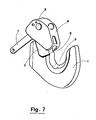
- the hook end 1 incorporates a seat 2, generally with a ball shaped surface, which is designed to accommodate a relative link ball (illustrated in broken line) with which the hitched implement is provided, and incorporates a substantially vertical appendage 3 which is located at the side of the hook opposite to that from which the link ball of the implement is hitched and unhitched.
- a safety catch which is embodied hollow and fits over the appendage 3, hinging therewith by way of a pin 5 and thus rotatable about the axis of this pin, which is fixed.
- the catch 4 moves from a locking position, into which it is urged continually by first tension means consisting of a coil spring 6 and in which it projects over the seat 2 in such a way as to retain the link ball therein, to a release position, gained by clockwise rotation of the catch itself, in which it no longer projects over the seat and therefore offers no obstruction to passage of the link ball.
- the hook end according to the invention comprises a ratchet-type mechanism; in a first embodiment of the mechanism illustrated in fig 4, the ratchet component consists of a first contoured yoke 8, and the pawl consists of a second contoured yoke 9.
- the first such yoke 8 comprises two members that exhibit dissimilar contours (see fig 4) and are interconnected by metal bridging pieces 22, and embodied thus, can be slipped over the appendage 3 of the hook.
- the two members are provided with respective slots 12 which freely accommodate the fixed pin 5, in such a way that the yoke 8 can be hinged thereto.
- the second yoke 9, which constitutes the pawl of the ratchet-type mechanism, likewise comprises two dis- similarly contoured members (fig 6) interconnected by a metal bridging piece 23.
- the yoke 9 is located internally of the hollow-bodied safety catch 4 and to the rear of the yoke 8 that constitutes the ratchet component of the mechanism, rotatable about a hinge pin 15 which is made fast to the catch 4 at a given point above the pin 5 having the fixed axis.
- the leaf spring 11 denotes a leaf spring located within the hollow-bodied safety catch 4, one end of which is seated on the top bridging piece 22 of the first yoke 8, the remaining end urging against the rear of the bridging piece 23 of the second yoke 9, or pawl; the central section of the spring is located underneath the pawl hinge pin 15.
- the leaf spring 11 thus provides second tension means which exert a continual pressure on the first yoke 8 or ratchet component, causing it to protrude forward beyond the catch as a result of downward movement occasioned by such pressure.
- the same spring 11 also constitutes third tension means which urge the pawl against the ratchet, since the pressure exerted by the spring on the second yoke 9 is such as to bias it continuously toward the first yoke 8.
- the hook end according to the invention further comprises means of release that work against the action of the third tension means, i.e. the leaf spring 11, and are designed to separate the pawl component from the ratchet component by disengaging the spur 17 from the recess 16.
- Such means consist of a second contact pin 19 which is integral with the latch 7 and engages in a arched slot 20 set in the side of the safety catch 4.
- the contact pin 19 is of length such as to penetrate into the hollow of the catch, and rotation of the latch 7, which is hinged to the fixed pin 5, will bring it up against one of the two members of the second yoke 9; the second yoke is thus caused to turn on its hinge pin 15 and separate from the first yoke 8.
- the hook appendage 3 is provided at rear with a projection 24 beneath which the bridging piece 23 of the pawl locates whenever the ratchet mechanism assumes the second position, in such a way as to inhibit upward movement of the pawl.
- a plate would be provided with a single slot 12a, corresponding to the pair of slots 12 aforedescribed and performing the same function, which accommodates the fixed pin 5, also, with a spur 17a corresponding to the spur 17 aforedescribed and performing the same function, and with a slot 13a, corresponding to the slot 13 aforedescribed and performing the same function, in which the first contact pin 14 may engage.
- the plate 8a thus embodied would be provided with a bridging piece 22a, the position of which corresponds exactly to the position of the bridging piece 22 of the yoke 8; one end of the leaf spring 11 would thus be seated on this bridging piece 22a in exactly the same fashion as for the yoke type ratchet component described above.
- the link ball When the link ball is offered to the hook end, it is the ball itself which shifts the safety catch 4 and causes its rotation in a clockwise direction, drawing with it the ratchet component, by way of the contact pin 14, and the pawl component, by way of the hinge pin 15.
- the link ball comes up ultimately against the protruding end of the ratchet component and causes it to slide upwards such that the spur 17/17a may engage in the recess 16 offered by the pawl 9 which, under pressure from the leaf spring 11, is urged down onto the ratchet.
- the latch 7 is rotated by the operator in a clockwise direction.
- the second contact pin 19 urges against one of the members of the pawl 9 in such a way as to turn it clockwise, thereby lifting the pawl itself and separating it both from the ratchet and from the projection 24 of the appendage.
- the ratchet mechanism is thus brought into the third position illustrated in fig 3, .and rotating the latch further, the pin 19, which by now has separated the pawl from the ratchet, reaches the end of the slot 20 and engages the safety catch 4, causing it to rotate into the release position that allows the link ball to exit from the seat.
- the ratchet component With the link ball freed from the seat, the ratchet component is urged downward by the leaf spring 11 in such a way as to project over the seat; such pressure also produces downward shift of the spur 17/17a.
- the hook end disclosed herein thus offers a twofold safety system guarding against accidental unhitching of the implement from the linkage -viz, in addition to the standard safety catch which projects over the seat of the hook, one has the supplementary safety feature of a ratchet-type mechanism which, with the link ball fast in the seat, impedes rotation of the catch, thereby preventing possible separation of the link ball from the seat of the hook end. It will be observed that this safety feature is obtained without in any way abandoning the auto hitch facility offered by such a hook end; releasing the link ball, the hook is automatically reset to enable repeat of the hitching operation in similar fashion.
Landscapes
- Life Sciences & Earth Sciences (AREA)
- Engineering & Computer Science (AREA)
- Mechanical Engineering (AREA)
- Environmental Sciences (AREA)
- Zoology (AREA)
- Soil Sciences (AREA)
- Transportation (AREA)
- Agricultural Machines (AREA)
- Hooks, Suction Cups, And Attachment By Adhesive Means (AREA)
- Escalators And Moving Walkways (AREA)
- Seats For Vehicles (AREA)
- Load-Engaging Elements For Cranes (AREA)
- Conveying And Assembling Of Building Elements In Situ (AREA)
Priority Applications (1)
| Application Number | Priority Date | Filing Date | Title |
|---|---|---|---|
| AT86830005T ATE43043T1 (de) | 1985-01-11 | 1986-01-08 | Automatischer schnell loesender kupplungshaken fuer ein dreipunktgestaenge mit einem doppelten blockiersystem gegen unerwuenschtes entkuppeln. |
Applications Claiming Priority (2)
| Application Number | Priority Date | Filing Date | Title |
|---|---|---|---|
| IT40004/85A IT1187133B (it) | 1985-01-11 | 1985-01-11 | Gancio a collegamento rapido automatico per attacco a tre punti,con doppio sistema di sicurezza contro lo sganciamento accidentale |
| IT4000485 | 1985-01-11 |
Publications (3)
| Publication Number | Publication Date |
|---|---|
| EP0187733A2 true EP0187733A2 (de) | 1986-07-16 |
| EP0187733A3 EP0187733A3 (en) | 1987-08-26 |
| EP0187733B1 EP0187733B1 (de) | 1989-05-17 |
Family
ID=11246362
Family Applications (1)
| Application Number | Title | Priority Date | Filing Date |
|---|---|---|---|
| EP86830005A Expired EP0187733B1 (de) | 1985-01-11 | 1986-01-08 | Automatischer schnell lösender Kupplungshaken für ein Dreipunktgestänge mit einem doppelten Blockiersystem gegen unerwünschtes Entkuppeln |
Country Status (4)
| Country | Link |
|---|---|
| EP (1) | EP0187733B1 (de) |
| AT (1) | ATE43043T1 (de) |
| DE (1) | DE3663320D1 (de) |
| IT (1) | IT1187133B (de) |
Cited By (5)
| Publication number | Priority date | Publication date | Assignee | Title |
|---|---|---|---|---|
| EP0412451A1 (de) * | 1989-08-11 | 1991-02-13 | SAME S.p.A. | Anhängerkupplung für landwirtschaftlichen Trecker oder dergleichen |
| FR2710585A1 (fr) * | 1993-09-28 | 1995-04-07 | Walterscheid Gmbh Gkn | Crochet d'accouplement, notamment pour un dispositif d'attelage d'une machine agricole. |
| WO2002085095A3 (de) * | 2001-04-24 | 2003-01-03 | Wgf Fahrzeugteile Gmbh | Kupplungshaken für den unterlenker eines traktors |
| ITTO20120708A1 (it) * | 2012-08-07 | 2014-02-08 | B C M Bersano Carpenterie Metallic He S R L | Gancio d'attacco di un'attrezzatura operatrice, particolarmente per un gruppo sollevatore di una macchina agricola. |
| CN114590370A (zh) * | 2022-03-01 | 2022-06-07 | 江门市南洋船舶工程有限公司 | 一种随动引船落墩及出坞设备 |
Family Cites Families (6)
| Publication number | Priority date | Publication date | Assignee | Title |
|---|---|---|---|---|
| US2979137A (en) * | 1958-03-17 | 1961-04-11 | Deere & Co | Tractor-pickup hitch |
| DE1457670A1 (de) * | 1964-12-19 | 1969-05-29 | Ernst Conrad | Dreipunkthakenkupplung fuer Ackerschlepper |
| FR1443201A (fr) * | 1965-04-21 | 1966-06-24 | Prillinger Hans Fa | Accouplement rapide pour engins de culture portés munis d'axes d'accouplement et se montant sur un tracteur à système hydraulique |
| DE1264845B (de) * | 1966-01-27 | 1968-03-28 | Deere & Co | Lenker fuer die Dreipunktgeraetekupplung von Schleppern |
| US4019753A (en) * | 1975-11-13 | 1977-04-26 | Kestel Frederick J | Adjustable three-point tractor hitch |
| DE3021343A1 (de) * | 1980-06-06 | 1981-12-17 | Ernst 3101 Nienhagen Conrad | Fangvorrichtung fuer die kugel an der aufhaengung eines anbaugeraetes an einer dreipunktaufhaengung, insbesondere fuer schlepper |
-
1985
- 1985-01-11 IT IT40004/85A patent/IT1187133B/it active
-
1986
- 1986-01-08 DE DE8686830005T patent/DE3663320D1/de not_active Expired
- 1986-01-08 EP EP86830005A patent/EP0187733B1/de not_active Expired
- 1986-01-08 AT AT86830005T patent/ATE43043T1/de not_active IP Right Cessation
Cited By (5)
| Publication number | Priority date | Publication date | Assignee | Title |
|---|---|---|---|---|
| EP0412451A1 (de) * | 1989-08-11 | 1991-02-13 | SAME S.p.A. | Anhängerkupplung für landwirtschaftlichen Trecker oder dergleichen |
| FR2710585A1 (fr) * | 1993-09-28 | 1995-04-07 | Walterscheid Gmbh Gkn | Crochet d'accouplement, notamment pour un dispositif d'attelage d'une machine agricole. |
| WO2002085095A3 (de) * | 2001-04-24 | 2003-01-03 | Wgf Fahrzeugteile Gmbh | Kupplungshaken für den unterlenker eines traktors |
| ITTO20120708A1 (it) * | 2012-08-07 | 2014-02-08 | B C M Bersano Carpenterie Metallic He S R L | Gancio d'attacco di un'attrezzatura operatrice, particolarmente per un gruppo sollevatore di una macchina agricola. |
| CN114590370A (zh) * | 2022-03-01 | 2022-06-07 | 江门市南洋船舶工程有限公司 | 一种随动引船落墩及出坞设备 |
Also Published As
| Publication number | Publication date |
|---|---|
| EP0187733A3 (en) | 1987-08-26 |
| DE3663320D1 (en) | 1989-06-22 |
| IT8540004A0 (it) | 1985-01-11 |
| ATE43043T1 (de) | 1989-06-15 |
| EP0187733B1 (de) | 1989-05-17 |
| IT1187133B (it) | 1987-12-16 |
Similar Documents
| Publication | Publication Date | Title |
|---|---|---|
| US4579191A (en) | Operator restraint system | |
| US5050684A (en) | Coupling hook | |
| CA1268499A (en) | Quick attach coupling | |
| US4758015A (en) | Latch mechanism for hitch assembly | |
| CA1248154A (en) | Trailer hitch | |
| US5497835A (en) | Coupling hook for the lower steering arms of a three-point attaching device of a tractor | |
| HUP0103509A2 (hu) | Ötödik kerék kapcsoló | |
| US4398745A (en) | Three point hitch lower link claw | |
| US5441117A (en) | Coupling hook for the lower steering arms of a three-point attaching device of a tractor | |
| CA2011456C (en) | Pintle type trailer coupling | |
| CA1219454A (en) | Pivotal handle mount | |
| CA1040679A (en) | Coupling hook for a three-point connection on a tractor | |
| FR2687039B1 (fr) | Faucheuse avec un dispositif de verrouillage perfectionne. | |
| EP0187733B1 (de) | Automatischer schnell lösender Kupplungshaken für ein Dreipunktgestänge mit einem doppelten Blockiersystem gegen unerwünschtes Entkuppeln | |
| US4817979A (en) | Trailer coupler | |
| CA1105518A (en) | Trailer couplings | |
| US4295389A (en) | Adjustable length upper guide member | |
| US4023822A (en) | Coupling hook for a guide member of a tractor three-point attachment | |
| US4108464A (en) | Coupling hook for a three-point attachment of a tractor | |
| CA2095949C (en) | Self aligning hitch | |
| US4126057A (en) | Adjustable length upper guide member | |
| DE69813509T2 (de) | Schnalle | |
| US4116280A (en) | Spring reset mechanism | |
| EP1745949B1 (de) | Anhängerkupplung mit Einrastsicherung | |
| EP0523332B1 (de) | Automatischer Ver- und Entriegelungsmechanismus für Dreipunktgestänge |
Legal Events
| Date | Code | Title | Description |
|---|---|---|---|
| PUAI | Public reference made under article 153(3) epc to a published international application that has entered the european phase |
Free format text: ORIGINAL CODE: 0009012 |
|
| AK | Designated contracting states |
Kind code of ref document: A2 Designated state(s): AT DE FR GB |
|
| PUAL | Search report despatched |
Free format text: ORIGINAL CODE: 0009013 |
|
| AK | Designated contracting states |
Kind code of ref document: A3 Designated state(s): AT DE FR GB |
|
| 17P | Request for examination filed |
Effective date: 19871223 |
|
| 17Q | First examination report despatched |
Effective date: 19880323 |
|
| GRAA | (expected) grant |
Free format text: ORIGINAL CODE: 0009210 |
|
| AK | Designated contracting states |
Kind code of ref document: B1 Designated state(s): AT DE FR GB |
|
| PG25 | Lapsed in a contracting state [announced via postgrant information from national office to epo] |
Ref country code: AT Effective date: 19890517 |
|
| REF | Corresponds to: |
Ref document number: 43043 Country of ref document: AT Date of ref document: 19890615 Kind code of ref document: T |
|
| REF | Corresponds to: |
Ref document number: 3663320 Country of ref document: DE Date of ref document: 19890622 |
|
| ET | Fr: translation filed | ||
| PLBE | No opposition filed within time limit |
Free format text: ORIGINAL CODE: 0009261 |
|
| 26N | No opposition filed | ||
| PGFP | Annual fee paid to national office [announced via postgrant information from national office to epo] |
Ref country code: GB Payment date: 19990121 Year of fee payment: 14 |
|
| PGFP | Annual fee paid to national office [announced via postgrant information from national office to epo] |
Ref country code: DE Payment date: 19990125 Year of fee payment: 14 |
|
| PGFP | Annual fee paid to national office [announced via postgrant information from national office to epo] |
Ref country code: FR Payment date: 19990126 Year of fee payment: 14 |
|
| PG25 | Lapsed in a contracting state [announced via postgrant information from national office to epo] |
Ref country code: GB Free format text: LAPSE BECAUSE OF NON-PAYMENT OF DUE FEES Effective date: 20000108 |
|
| GBPC | Gb: european patent ceased through non-payment of renewal fee |
Effective date: 20000108 |
|
| PG25 | Lapsed in a contracting state [announced via postgrant information from national office to epo] |
Ref country code: FR Free format text: LAPSE BECAUSE OF NON-PAYMENT OF DUE FEES Effective date: 20000929 |
|
| PG25 | Lapsed in a contracting state [announced via postgrant information from national office to epo] |
Ref country code: DE Free format text: LAPSE BECAUSE OF NON-PAYMENT OF DUE FEES Effective date: 20001101 |
|
| REG | Reference to a national code |
Ref country code: FR Ref legal event code: ST |