EP0187579A1 - Electromagnetic resonators and filters comprising such resonators - Google Patents
Electromagnetic resonators and filters comprising such resonators Download PDFInfo
- Publication number
- EP0187579A1 EP0187579A1 EP85402432A EP85402432A EP0187579A1 EP 0187579 A1 EP0187579 A1 EP 0187579A1 EP 85402432 A EP85402432 A EP 85402432A EP 85402432 A EP85402432 A EP 85402432A EP 0187579 A1 EP0187579 A1 EP 0187579A1
- Authority
- EP
- European Patent Office
- Prior art keywords
- bar
- resonator
- resonator according
- dielectric
- electrodes
- Prior art date
- Legal status (The legal status is an assumption and is not a legal conclusion. Google has not performed a legal analysis and makes no representation as to the accuracy of the status listed.)
- Granted
Links
- 238000001465 metallisation Methods 0.000 claims description 34
- 230000002787 reinforcement Effects 0.000 claims description 6
- 238000004080 punching Methods 0.000 claims description 4
- 239000002184 metal Substances 0.000 description 18
- 229910052751 metal Inorganic materials 0.000 description 18
- 238000000034 method Methods 0.000 description 17
- 230000008878 coupling Effects 0.000 description 11
- 238000010168 coupling process Methods 0.000 description 11
- 238000005859 coupling reaction Methods 0.000 description 11
- 239000000758 substrate Substances 0.000 description 9
- 239000003989 dielectric material Substances 0.000 description 8
- 238000004519 manufacturing process Methods 0.000 description 6
- 230000008901 benefit Effects 0.000 description 5
- RYGMFSIKBFXOCR-UHFFFAOYSA-N Copper Chemical compound [Cu] RYGMFSIKBFXOCR-UHFFFAOYSA-N 0.000 description 4
- BQCADISMDOOEFD-UHFFFAOYSA-N Silver Chemical compound [Ag] BQCADISMDOOEFD-UHFFFAOYSA-N 0.000 description 4
- 239000000853 adhesive Substances 0.000 description 4
- 230000001070 adhesive effect Effects 0.000 description 4
- 239000004020 conductor Substances 0.000 description 4
- 229910052802 copper Inorganic materials 0.000 description 4
- 239000010949 copper Substances 0.000 description 4
- 229910052709 silver Inorganic materials 0.000 description 4
- 239000004332 silver Substances 0.000 description 4
- 230000007547 defect Effects 0.000 description 3
- 239000003292 glue Substances 0.000 description 3
- 238000011065 in-situ storage Methods 0.000 description 3
- IJGRMHOSHXDMSA-UHFFFAOYSA-N Atomic nitrogen Chemical compound N#N IJGRMHOSHXDMSA-UHFFFAOYSA-N 0.000 description 2
- FFTDWVOLFHWSSJ-UHFFFAOYSA-N barium(2+);oxygen(2-);titanium(4+) Chemical compound [O-2].[O-2].[O-2].[O-2].[O-2].[O-2].[O-2].[O-2].[O-2].[Ti+4].[Ti+4].[Ti+4].[Ti+4].[Ba+2] FFTDWVOLFHWSSJ-UHFFFAOYSA-N 0.000 description 2
- 230000015556 catabolic process Effects 0.000 description 2
- 230000003247 decreasing effect Effects 0.000 description 2
- 238000006731 degradation reaction Methods 0.000 description 2
- 238000000151 deposition Methods 0.000 description 2
- 230000005684 electric field Effects 0.000 description 2
- PCHJSUWPFVWCPO-UHFFFAOYSA-N gold Chemical compound [Au] PCHJSUWPFVWCPO-UHFFFAOYSA-N 0.000 description 2
- 229910052737 gold Inorganic materials 0.000 description 2
- 239000010931 gold Substances 0.000 description 2
- 238000003780 insertion Methods 0.000 description 2
- 230000037431 insertion Effects 0.000 description 2
- 238000000465 moulding Methods 0.000 description 2
- 230000009467 reduction Effects 0.000 description 2
- 238000004026 adhesive bonding Methods 0.000 description 1
- 230000032683 aging Effects 0.000 description 1
- 230000004075 alteration Effects 0.000 description 1
- 230000003042 antagnostic effect Effects 0.000 description 1
- 230000015572 biosynthetic process Effects 0.000 description 1
- 238000007796 conventional method Methods 0.000 description 1
- 230000007423 decrease Effects 0.000 description 1
- 230000008021 deposition Effects 0.000 description 1
- 238000013461 design Methods 0.000 description 1
- 239000006185 dispersion Substances 0.000 description 1
- 238000005868 electrolysis reaction Methods 0.000 description 1
- 230000005672 electromagnetic field Effects 0.000 description 1
- 230000008020 evaporation Effects 0.000 description 1
- 238000001704 evaporation Methods 0.000 description 1
- 230000017525 heat dissipation Effects 0.000 description 1
- 239000012943 hotmelt Substances 0.000 description 1
- 238000009776 industrial production Methods 0.000 description 1
- 239000004922 lacquer Substances 0.000 description 1
- 238000003754 machining Methods 0.000 description 1
- 239000000463 material Substances 0.000 description 1
- 230000008018 melting Effects 0.000 description 1
- 238000002844 melting Methods 0.000 description 1
- 230000007935 neutral effect Effects 0.000 description 1
- 229910052757 nitrogen Inorganic materials 0.000 description 1
- 230000003071 parasitic effect Effects 0.000 description 1
- 230000001105 regulatory effect Effects 0.000 description 1
- 238000012552 review Methods 0.000 description 1
- 239000007787 solid Substances 0.000 description 1
- 238000012360 testing method Methods 0.000 description 1
- 230000007704 transition Effects 0.000 description 1
Images
Classifications
-
- H—ELECTRICITY
- H01—ELECTRIC ELEMENTS
- H01P—WAVEGUIDES; RESONATORS, LINES, OR OTHER DEVICES OF THE WAVEGUIDE TYPE
- H01P7/00—Resonators of the waveguide type
- H01P7/08—Strip line resonators
-
- H—ELECTRICITY
- H01—ELECTRIC ELEMENTS
- H01P—WAVEGUIDES; RESONATORS, LINES, OR OTHER DEVICES OF THE WAVEGUIDE TYPE
- H01P7/00—Resonators of the waveguide type
- H01P7/02—Lecher resonators
-
- H—ELECTRICITY
- H01—ELECTRIC ELEMENTS
- H01P—WAVEGUIDES; RESONATORS, LINES, OR OTHER DEVICES OF THE WAVEGUIDE TYPE
- H01P7/00—Resonators of the waveguide type
- H01P7/10—Dielectric resonators
Definitions
- the present invention relates to electromagnetic resonators as well as the high frequency filters produced from these resonators.
- these resonators can be called biruban, bifilar, quadrilateral or quadrifilar resonators.
- the resonators and filters produced from these elements often consist of line sections. It can be air coaxial lines or coaxial lines loaded with dielectrics as mentioned in the article: "Bandpass filter with dielectric materials used for broadcasting channel filter” by K.WAKINO and Y.KONISHI published in the review I.E.E.E. Transactions on Broadcasting, vol. BC-26, No. 1, March 1980. It is also known to manufacture resonators and filters from microstrip lines as the article indicates: "750 MHz microstrip bandpass filter on barium tetratitanate substrate" by G. OHM and G. SCHMOLLER published in the magazine Electronics Letters, vol. 18, No. 15 of July 22, 1982.
- the coaxial line technique allows the manufacture of independent resonators whose natural frequencies can be adjusted before their assembly to form filters.
- This assembly can be achieved in the case of a bandpass filter by placing the various resonators end to end, the couplings between two sections of consecutive lines being determined by the distances which separate their faces placed opposite.
- overvoltage coefficients greater than 500
- a silver metallized 20 mm diameter resonator can have an overvoltage coefficient Q greater than 1000 for a frequency of 1 GHz.
- the coupling of quarter-wave resonators remains delicate and the very realization of the coaxial structure is quite complex because of the different operations of machining and metallization of elements with circular section.
- Resonators can be designed using the microstrip line technique. They are generally produced from a relatively large dielectric substrate, one face of which is entirely metallized and the other of which receives a metallic conductor in the form of a thin strip. This technique has two drawbacks. On the one hand, the inherent overvoltage coefficients Q of the resonators are always low (less than 500) and consequently the performance of filters formed from these resonators is always modest (high insertion losses, greater than 3 dB towards 1 GHz). On the other hand, once the filter has been produced, by depositing ribbons on the same substrate, it is practically impossible to adjust the natural frequencies of the resonators as well as their mutual couplings. This prohibits the industrial production of filters comprising a high number of poles due to the inevitable dispersions of the characteristics: in particular, the dielectric constant of the substrate.
- the invention proposes resonators which can be in different forms or configurations in order to offer a minimum bulk, whether they are used alone or in combination to form filters.
- One of the solutions consists in modifying the geometry of the dielectrics in order to lower the resonant frequency without increasing the volume of the resonator.
- Another solution is to judiciously reduce the width of the metallizations.
- the subject of the invention is therefore a quarter wave electromagnetic resonator of the type comprising a dielectric bar of polygonal section delimiting at least six faces, the bar being disposed between at least two electrodes joined by a short circuit to one of their ends, characterized in that the electrodes and their short-circuit are part of a U-shaped armature, the electrodes only partially covering the faces of the bar which are adjacent to them.
- the subject of the invention is also a quarter wave electromagnetic resonator of the type comprising a dielectric bar of polygonal section delimiting at least six faces, the bar being covered on two of its opposite faces with a metallization playing the role of electrodes, characterized in that the dielectric bar has, on the open circuit side, a reduced section with respect to the rest of the bar so as to reduce the distance separating the electrodes.
- the subject of the invention is also a quarter wave electromagnetic resonator of the type comprising a dielectric bar of polygonal section delimiting at least six faces, the bar being covered on two of its opposite faces with a metallization acting as electrodes, characterized in that the dielectric bar has, on the short-circuit side, a reduced section relative to the rest of the bar so as to reduce the width of the metallization.
- the invention also relates to a high frequency bandpass filter, characterized in that it comprises at least one resonator as defined above.
- the object of the invention being to minimize the size of the resonators, these will be chosen of the quarter wave type.
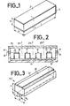
- FIG. 1 represents a quarter wave resonator according to known art and called biruban resonator. It consists of a solid dielectric 1 of parallelepiped shape and having a rectangular section of sides a and b. Metallizations 2 and 3 cover the two opposite faces of the parallelepiped which are separated by the distance a. The metallization 4 located at one end of the dielectric rod 1 constitutes a short circuit for the electrodes 2 and 3.
- Figure 2 is a sectional view of such a filter with four resonators 10, 11, 12 and 13 disposed on an insulating substrate 14 which has a very low dielectric constant.
- the resonators are fixed to the substrate by gluing.
- the metallizations of the main faces (electrodes) of the resonators are mutually parallel and perpendicular to the substrate.
- the coupling between resonators is done by mutual inductance.
- the natural frequencies of each resonator have been previously adjusted either by manufacturing or by running in.
- the assembly formed by the support 14 and the four resonators is placed in a housing 15 connected to ground and closed by a metal cover 22.
- the hole 16 allows the passage of a conductor 18 which forms a coupling loop 20, serving as an exciter means, with the resonator 10.
- the end of the conductor 18 is then connected to the housing.
- the output signal is similarly picked up by the conductor 19 which forms a loop 21 which serves as collector means at the level of the resonator 13.
- adjustment screws along axes 23, 24 and 25. These screws located between the resonators modify, according to their more or less great depression, the electromagnetic field which reigns between the resonators.
- the filter shown in Figure 2 which also gives good results, has the disadvantage of occupying a large volume relative to the size of the resonators. Indeed, it is necessary to provide an insulating substrate 14 at the bottom of the housing, which is metallic for shielding purposes, in order to avoid short-circuiting the metallizations of the resonators. In addition, this substrate must have a sufficient thickness to prevent the metallic mass of the housing from influencing the setting and the overvoltage coefficient of the resonators. Likewise, the metal cover 22 must be located at a sufficient distance. We see that with these dimensional characteristics, the volume occupied by a filter can be significant relative to the volume of the resonators.
- the resonators described above have three fully metallized faces which requires the presence of an insulating support to ensure their mounting in a housing.
- the invention proposes to use metallized resonators on a band narrower than their own width.
- Figure 3 shows such a resonator.
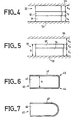
- the resonator proper which bears the reference 30, consists of a dielectric bar 31, preferably having the shape of a rectangular parallelepiped, partially covered with a metallization 32 which provides electrical continuity on two main and opposite faces of the bar and the 'one end.
- the conductive strip 32 has a constant width h 2 . It is located at a distance h l from one of the edges of the bar and at a distance h 3 from the other edge of the face considered.
- a resonator such as that shown in Figure 3 can be fixed without risk of short circuit directly on a metal plane and even be inserted between two metal planes as shown in Figure 4.
- the metal planes 33 and 34 can be respectively part of 'a housing and its cover.
- the distances h l and h 3 should be sufficient so that the metallic masses 33 and 34 do not disturb the agreement which it is desired to obtain.
- the arrangement in FIG. 4 promotes the dissipation of the dissipated heat and ensures better frequency stability of the resonator with respect to temperature variations and vibrations.
- the overvoltage of the resonator in its housing then remains very close to the inherent overvoltage of the resonator.
- the degradation of the overvoltage coefficient is less than 20% around 900 MHz for a copper or gold case.
- FIG. 5 Another metallization arrangement is advantageous. This is the one shown in FIG. 5 where a resonator according to the invention is placed between two metal planes which can be part of the housing and of the cover of a filter.
- the resonator 35 formed by the bar 36 and the metallization 37 is disposed on the metal plane 38.
- the metal plane 39 is located at a distance h ' 3 from the resonator.
- the value of the overvoltage coefficient Q depends on the quality of the metallization supported by the dielectric bar.
- the formation of electrodes by metallization presents a delicate point which is the need to have a regular metallic layer in particular at the sharp angles formed by the junction of the electrodes and the end short-circuit.
- the thickness of the metallization being relatively thin, the abrupt transition of a plane metallization to another which is perpendicular thereto can cause defects in the thickness of the deposit which has the consequence of varying the overvoltage coefficient from one resonator to another which theoretically is identical to it. It is possible to overcome this drawback by rounding off the angles which must be metallized.
- Figure 6 is a side view of such a resonator.
- the resonator 40 is formed by the dielectric bar 41 covered with a metallization 42 playing as previously the role of electrodes and short-circuit. Note in this figure that the angles 43 and 44 have been rounded which contributes to making the deposited layer uniform. For example, the radius of curvature of these rounding can be of the order of one tenth of the distance a.
- FIG. 7 where the resonator 45 is formed by the dielectric bar 46 partially covered with a metallization 47.
- the metallization can be made of silver or copper deposited by a conventional technique: sintered lacquer, evaporation, electrolysis ...
- the recommended thickness is at least 30 ⁇ m for a resonance frequency of 1 GHz.
- the two-wire electrodes can be produced by means of a metal frame which can be deposited as a layer as above, but which will preferably be added. The frame will then appear in the form of a jumper typically made of copper or silver or gold metal. The section of dielectric material can then be shortened. Typically, the length 1 of the section will be approximately half the length of the electrodes.
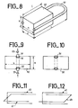
- Figure 8 is an isometric view of a two-wire resonator according to the invention.
- the resonator comprises a dielectric rod 50 having the shape of a rectangular parallelepiped of length 1 and of section a x b as shown in the figure.
- the resonator also includes the jumper or armature 51 of length L which encloses the rod 50 by embedding and which constitutes both the two electrodes of the resonator and their short-circuit.
- the jumper 51 can have different shapes, for example in the shape of a U as shown in FIG. 8.
- the resonant frequency and the overvoltage coefficient Q are mainly determined by the length L of the electrodes, the distance between these electrodes and the nature of the dielectric.
- the length 1 of the bar 50 can be reduced up to approximately x without appreciable alteration of the main characteristics of the resonator.
- the first method leads to poor overvoltage coefficients and unstable resonance frequencies due to the thickness of the adhesive joint and the dielectric losses of the insulating adhesive.
- the second method provides better performance because the joint is thinner and the dielectric losses of this kind of glue are weaker.
- the sintered conductive adhesive of the third method ensures excellent contact and therefore good frequency stability. However, due to its poor conductivity, it is difficult to obtain a very low surface resistance and the overvoltage is degraded.
- the size of the glue affects the value of the resonant frequency. If the glued area increases, the resonant frequency decreases. We can take advantage of this property and increase the conductive bonded surface taking into account the influences of the external metal parts (case, cover) to lower the resonant frequency by a factor of 2 or 3 without increasing the bulk.
- the embedding technique of the fourth method makes it possible to obtain the highest overvoltages.
- the frequency stability depends a lot on the quality of the embedding.
- the best results are obtained by hot punching under a neutral atmosphere, for example at 500 ° C. under nitrogen, optionally followed by an aging stage carried out under the same conditions.
- the duration of the landing can be of the order of one hour.
- Figure 9 shows the same resonator as that shown in Figure 8 but seen at one of its ends.
- the jumper 51 is placed in a housing 52 intended to receive it and made in the bar 50.
- the punches 53 act on the jumper 51 in the direction indicated by the arrows in order to embed the jumper.
- Figure 10 shows the result obtained after punching.
- the fifth method, in situ molding, requires the use of dielectric parts forming the negative impression of the metal part. This can be preformed and placed in the dielectric. The whole is brought to a temperature slightly higher than the melting temperature of the metal and then cooled slowly. Silver works particularly well.
- the jumper is made of copper and is embedded by punching. Under these conditions, the overvoltage coefficient Q is equal to 1000 at the frequency of 950 MHz. This is a very good result given the size of the resonator.
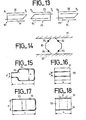
- FIG. 13 schematically represents the arrangement envisaged for a filter with three resonators 70, 73 and 76. These are quarter-wave resonators with two resonances. They are formed as for FIG. 12 of metallic reinforcements enclosing a dielectric bar not shown and situated in planes perpendicular to one another.
- the resonator 70 includes the pairs of frames 71 and 72, the resonator 73 includes the couples 74 and 75 and the resonator 76 includes the couples 77 and 78.
- the resonators are placed in the extension of each other as shown in Figure 13.
- the armatures 71 and 74 located in the same plane or in parallel planes provide a preponderant magnetic coupling between the resonators 70 and 73.
- the value of these couplings is adjusted by the distances between resonators.
- the input signal is injected via a coupling loop at the pole P 1 .
- the output signal is extracted in the same way at the P6 pole. Couplings of the intra-resonator type are rather ensured by the electric fields in the dielectric and are regulated by the defects of symmetry of the resonator (defect of orthogonality of two armatures, influence of the case, etc.).
- the resonators which can be used in this type of filter can be produced using techniques described for the manufacture of biruban or bifilar resonators.
- the very section of the dielectric is determined by additional considerations (heat dissipation, convenience of fixing) and can be square, round, octagonal.
- FIG. 14 represents the octagonal section of a dielectric bar 80 equipped with two armatures 83 and 84 placed in perpendicular planes. The resonator thus formed can be placed without inconvenience between two metal surfaces 81 and 82.
- FIGS. 17 and 18 represent front and side views of a quarter wave resonator formed by a dielectric bar 95 covered with a metallization 96 on two opposite faces and one end.
- the resonator includes sections of different surfaces.
- the inter-electrode width remains constant but it is the transverse dimension of the bar which changes. This dimension which is worth b near the open circuit, is worth b ' ⁇ b near the short circuit. This has the consequence of increasing the inductance and therefore of decreasing the resonant frequency.
- the dielectric material it is essential to choose the dielectric material so as to compensate for thermal drifts.
- the coefficient expressing the first order drift in temperature equal to 0 ppm / ° C.
- the reinforcement is only partially secured to the dielectric, it is necessary to compensate for the expansion of the metal by choosing coefficients typically between + 10 and + 20 ppm / ° C. Dielectrics having these characteristics The techniques have been described in the French patent published under the number FR-A-2 477 823.
Landscapes
- Control Of Motors That Do Not Use Commutators (AREA)
Abstract
Description
La présente invention concerne les résonateurs électromagnétiques ainsi que les filtres hautes fréquences réalisés à partir de ces résonateurs. Selon les cas, ces résonateurs peuvent être appelés résonateurs birubans, bifilaires, quadrirubans ou quadrifilaires.The present invention relates to electromagnetic resonators as well as the high frequency filters produced from these resonators. Depending on the case, these resonators can be called biruban, bifilar, quadrilateral or quadrifilar resonators.
Dans la gamme des fréquences élevées appelées UHF (pratiquement de 300 MHz à 3 Ghz), les résonateurs et les filtres réalisés à partir de ces éléments sont souvent constitués de tronçons de lignes. Il peut s'agir de lignes coaxiales à air ou de lignes coaxiales chargées de diélectriques telles que mentionnées dans l'article : "Bandpass filter with dielectric materials used for broadcasting channel filter" de K.WAKINO et Y.KONISHI paru dans la revue I.E.E.E. Transactions on Broadcasting, vol. BC-26, No. 1, mars 1980. Il est connu aussi de fabriquer des résonateurs et des filtres à partir de lignes microrubans comme l'indique l'article : "750 MHz microstrip bandpass filter on barium tetratitanate substrate " de G. OHM et G. SCHMOLLER paru dans la revue Electronics Letters, vol. 18, No. 15 du 22 juillet 1982.In the range of high frequencies called UHF (practically from 300 MHz to 3 Ghz), the resonators and filters produced from these elements often consist of line sections. It can be air coaxial lines or coaxial lines loaded with dielectrics as mentioned in the article: "Bandpass filter with dielectric materials used for broadcasting channel filter" by K.WAKINO and Y.KONISHI published in the review I.E.E.E. Transactions on Broadcasting, vol. BC-26, No. 1, March 1980. It is also known to manufacture resonators and filters from microstrip lines as the article indicates: "750 MHz microstrip bandpass filter on barium tetratitanate substrate" by G. OHM and G. SCHMOLLER published in the magazine Electronics Letters, vol. 18, No. 15 of July 22, 1982.
La technique des lignes coaxiales autorise la fabrication de résonateurs indépendants dont les fréquences propres peuvent être ajustées avant leur assemblage pour former des filtres. Cet assemblage peut être réalisé dans le cas d'un filtre passe-bande en plaçant les différents résonateurs bout à bout, les couplages entre deux tronçons de lignes consécutifs étant déterminés par les distances qui séparent leurs faces placées en vis-à-vis. Cependant, pour obtenir des coefficients de surtension intéressants (supérieurs à 500) il faut disposer de tronçons ayant une section assez importante. Typiquement un résonateur d'un diamètre de 20 mm métallisé à l'argent peut avoir un coefficient de surtension Q supérieur à 1000 pour une fréquence de 1 GHz. En outre, le couplage des résonateurs quart d'onde demeure délicat et la réalisation même de la structure coaxiale est assez complexe à cause des différentes opérations d'usinage et de métallisation d'éléments à section circulaire.The coaxial line technique allows the manufacture of independent resonators whose natural frequencies can be adjusted before their assembly to form filters. This assembly can be achieved in the case of a bandpass filter by placing the various resonators end to end, the couplings between two sections of consecutive lines being determined by the distances which separate their faces placed opposite. However, to obtain interesting overvoltage coefficients (greater than 500) it is necessary to have sections having a fairly large section. Typically a silver metallized 20 mm diameter resonator can have an overvoltage coefficient Q greater than 1000 for a frequency of 1 GHz. In addition, the coupling of quarter-wave resonators remains delicate and the very realization of the coaxial structure is quite complex because of the different operations of machining and metallization of elements with circular section.
Des résonateurs peuvent être conçus selon la technique des lignes microrubans. Ils sont généralement réalisés à partir d'un substrat diélectrique relativement large dont une face est entièrement métallisée et dont l'autre reçoit un conducteur métallique sous la forme d'un mince ruban. Cette technique présente deux inconvénients. D'une part, les coefficients de surtension propres Q des résonateurs sont toujours faibles (inférieur à 500) et par conséquent les performances de filtres formés à partir de ces résonateurs sont toujours modestes (pertes d'insertion élevées, supérieures à 3 dB vers 1 GHz). D'autre part, une fois le filtre réalisé, par dépôt de rubans sur un même substrat, il est pratiquement impossible d'ajuster les fréquences propres des résonateurs ainsi que leurs couplages mutuels. Ceci interdit la réalisation industrielle de filtres comportant un nombre de pôles élevé en raison des inévitables dispersions des caractéristiques : en particulier, de la constante diélectrique du substrat.Resonators can be designed using the microstrip line technique. They are generally produced from a relatively large dielectric substrate, one face of which is entirely metallized and the other of which receives a metallic conductor in the form of a thin strip. This technique has two drawbacks. On the one hand, the inherent overvoltage coefficients Q of the resonators are always low (less than 500) and consequently the performance of filters formed from these resonators is always modest (high insertion losses, greater than 3 dB towards 1 GHz). On the other hand, once the filter has been produced, by depositing ribbons on the same substrate, it is practically impossible to adjust the natural frequencies of the resonators as well as their mutual couplings. This prohibits the industrial production of filters comprising a high number of poles due to the inevitable dispersions of the characteristics: in particular, the dielectric constant of the substrate.
Ces inconvénients ont été en partie palliés grâce à des résonateurs réalisés à partir de parallélépipèdes constitués de matériau diélectrique, métallisés sur deux faces opposées. On obtient un résonateur quart d'onde ou demi-onde suivant la longueur et la terminaison de la ligne. Ces résonateurs ont fait l'objet d'une demande de brevet de la Demanderesse déposée le 29 octobre 1982 et publiée sous le numéro FR-A-2 535 547. Cette demande de brevet décrit notamment l'utilisation de résonateurs quart d'onde pour la fabrication de filtres passe-bande. Le parallélépipède possède des métallisations sur deux de ses grandes faces, ces faces étant opposées l'une à l'autre et court-circuitées par une métallisation située à l'extrémité du parallélépipède. La conception même de ces résonateurs conduit à disposer de filtres présentant un certain encombrement d0 à la présence d'un support isolant et d'une distance minimale à respecter entre la masse métallique du bottier et les métallisations des résonateurs.These drawbacks have been partially remedied by resonators made from parallelepipeds made of dielectric material, metallized on two opposite faces. A quarter wave or half wave resonator is obtained depending on the length and termination of the line. These resonators were the subject of a patent application from the Applicant filed on October 29, 1982 and published under the number FR-A-2 535 547. This patent application describes in particular the use of quarter wave resonators for the manufacture of band pass filters. The parallelepiped has metallizations on two of its large faces, these faces being opposite to each other and short-circuited by a metallization located at the end of the parallelepiped. The very design of these resonators leads to having filters having a certain space requirement d0 in the presence of an insulating support and a minimum distance to be observed between the metal mass of the shoemaker and the metallizations of the resonators.
Afin de pallier ces inconvénients, l'invention propose des résonateurs pouvant se présenter sous différentes formes ou configurations afin d'offrir un encombrement minimal qu'ils soient utilisés isolément ou en association pour former des filtres. L'une des solutions consiste à modifier la géométrie des diélectriques afin d'abaisser la fréquence de résonance sans augmenter le volume du résonateur. Une autre solution consiste à réduire de façon judicieuse la largeur des métallisations.In order to overcome these drawbacks, the invention proposes resonators which can be in different forms or configurations in order to offer a minimum bulk, whether they are used alone or in combination to form filters. One of the solutions consists in modifying the geometry of the dielectrics in order to lower the resonant frequency without increasing the volume of the resonator. Another solution is to judiciously reduce the width of the metallizations.
L'invention a donc pour objet un résonateur électromagnétique quart d'onde du type comportant un barreau diélectrique de section polygonale délimitant au moins six faces, le barreau étant disposé entre au moins deux électrodes réunies par un court-circuit à l'une de leurs extrémités, caractérisé en ce que les électrodes et leur court-circuit font partie d'une armature en forme de U, les électrodes ne recouvrant que partiellement les faces du barreau qui leur sont adjacentes.The subject of the invention is therefore a quarter wave electromagnetic resonator of the type comprising a dielectric bar of polygonal section delimiting at least six faces, the bar being disposed between at least two electrodes joined by a short circuit to one of their ends, characterized in that the electrodes and their short-circuit are part of a U-shaped armature, the electrodes only partially covering the faces of the bar which are adjacent to them.
L'invention a encore pour objet un résonateur électromagnétique quart d'onde du type comportant un barreau diélectrique de section polygonale délimitant au moins six faces, le barreau étant recouvert sur deux de ses faces opposées d'une métallisation jouant le rôle d'électrodes, caractérisé en ce que le barreau diélectrique présente, côté circuit ouvert, une section réduite par rapport au reste du barreau de façon à réduire la distance séparant les électrodes.The subject of the invention is also a quarter wave electromagnetic resonator of the type comprising a dielectric bar of polygonal section delimiting at least six faces, the bar being covered on two of its opposite faces with a metallization playing the role of electrodes, characterized in that the dielectric bar has, on the open circuit side, a reduced section with respect to the rest of the bar so as to reduce the distance separating the electrodes.
L'invention a aussi pour objet un résonateur électromagnétique quart d'onde du type comportant un barreau diélectrique de section polygonale délimitant au moins six faces, le barreau étant recouvert sur deux de ses faces opposées d'une métallisation jouant le rôle d'électrodes, caractérisé en ce que le barreau diélectrique présente, côté court-circuit, une section réduite par rapport au reste du barreau de façon à réduire la largeur de la métallisation.The subject of the invention is also a quarter wave electromagnetic resonator of the type comprising a dielectric bar of polygonal section delimiting at least six faces, the bar being covered on two of its opposite faces with a metallization acting as electrodes, characterized in that the dielectric bar has, on the short-circuit side, a reduced section relative to the rest of the bar so as to reduce the width of the metallization.
L'invention a également pour objet un filtre passe-bande haute fréquence, caractérisé en ce qu'il comprend au moins un résonateur tel que défini ci-dessus.The invention also relates to a high frequency bandpass filter, characterized in that it comprises at least one resonator as defined above.
L'invention sera mieux comprise et d'autres avantages apparaîtront au moyen de la description qui va suivre et des figures annexées parmi lesquelles :
- - la figure 1 représente un résonateur quart d'onde selon l'art connu,
- - la figure 2 est une vue en coupe d'un filtre passe-bande selon l'art connu,
- - la figure 3 est une vue isométrique d'un résonateur selon l'invention,
- - les figures 4 et 5 représentent des résonateurs selon l'invention placés entre des plans métalliques,
- - les figures 6 et 7 représentent des résonateurs à angles métallisés arrondis,
- - la figure 8 est une vue isométrique d'un résonateur bifilaire selon l'invention,
- - les figures 9 et 10 sont illustratives d'une méthode de fixation d'une armature métallique sur un résonateur selon l'invention,
- - les figures 11 et 12 représentent schématiquement des résonateurs quadrifilaires ou quadrirubans selon l'invention,
- - la figure 13 représente schématiquement un filtre passe-bande,
- - la figure 14 représente un résonateur quadrifilaire à section octogonale,
- - les figures 15 à 18 représentent des résonateurs à géométrie particulière.
- FIG. 1 represents a quarter wave resonator according to known art,
- FIG. 2 is a sectional view of a bandpass filter according to the prior art,
- FIG. 3 is an isometric view of a resonator according to the invention,
- FIGS. 4 and 5 represent resonators according to the invention placed between metallic planes,
- FIGS. 6 and 7 represent resonators with rounded metallized angles,
- FIG. 8 is an isometric view of a two-wire resonator according to the invention,
- FIGS. 9 and 10 are illustrative of a method of fixing a metal frame to a resonator according to the invention,
- FIGS. 11 and 12 schematically represent quadrifilar or quadri-ribbon resonators according to the invention,
- FIG. 13 schematically represents a bandpass filter,
- FIG. 14 represents a quadrifilar resonator with an octagonal section,
- - Figures 15 to 18 show resonators with particular geometry.
L'objet de l'invention étant de réduire au maximum l'encombrement des résonateurs, ceux-ci seront choisis du type quart d'onde.The object of the invention being to minimize the size of the resonators, these will be chosen of the quarter wave type.
La figure 1 représente un résonateur quart d'onde selon l'art connu et appelé résonateur biruban. Il est constitué d'un solide diélectrique 1 de forme parallélépipédique et ayant une section rectangulaire de côtés a et b. Des métallisations 2 et 3 recouvrent les deux faces opposées du parallélépipède qui sont séparées par la distance a. La métallisation 4 située à l'une des extrémités du barreau diélectrique 1 constitue un court-circuit pour les électrodes 2 et 3. Une telle ligne propage des ondes électromagnétiques avec un indice efficace ne = λo λg X o représente la longueur d'onde dans le vide et X g la longueur d'onde dans le guide biruban. Cet indice dépend de la constante diélectrique du matériau et de la géométrie de la ligne. Ainsi, en utilisant un barreau de diélectrique en tétratitanate de baryum Ba Ti4 09 de constante diélectrique 37, et de dimensions a et b comprises entre 5 et 10 mm, on obtient, pour 1 GHz, ne = 4,7. La longueur L du barreau 1 étant égale à λg 4, on dispose bien un résonateur quart d'onde. Un tel résonateur permet d'obtenir de bons résultats. Par exemple, un barreau de dimensions a = b = 15 mm et L = 15 mm présente une fréquence de résonance de 1060 MHz pour un facteur de surtension Q = 1000.FIG. 1 represents a quarter wave resonator according to known art and called biruban resonator. It consists of a solid dielectric 1 of parallelepiped shape and having a rectangular section of sides a and b.
Il est connu d'utiliser de tels résonateurs pour élaborer des filtres passe-bande. La figure 2 est une vue en coupe d'un tel filtre à quatre résonateurs 10, 11, 12 et 13 disposés sur un substrat isolant 14 qui possède une très faible constante diélectrique. Les résonateurs sont fixés sur le substrat par collage. Les métallisations des faces principales (électrodes) des résonateurs sont parallèles entre elles et perpendiculaires au substrat. Le couplage entre résonateurs se fait par inductance mutuelle. Les fréquences propres de chaque résonateur ont été au préalable ajustées soit par fabrication, soit par rodage. L'ensemble formé par le support 14 et les quatre résonateurs est placé dans un boîtier 15 relié à la masse et fermé par un couvercle métallique 22. La coupe de la figure 2 a été réalisée au niveau des trous 16 et 17 d'entrée et de sortie du signal. Le trou 16 permet le passage d'un conducteur 18 qui forme une boucle 20 de couplage, servant de moyen excitateur, avec le résonateur 10. L'extrémité du conducteur 18 est ensuite reliée au boîtier. Le signal de sortie est prélevé de façon similaire par le conducteur 19 qui forme une boucle 21 qui sert de moyen collecteur au niveau du résonateur 13. Afin de procéder à des ajustements fins des couplages entre résonateurs, il est possible de placer des vis de réglage selon les axes 23, 24 et 25. Ces vis situées entre les résonateurs modifient, suivant leur enfoncement plus ou moins grand, le champ électromagnétique qui règne entre les résonateurs.It is known to use such resonators to develop bandpass filters. Figure 2 is a sectional view of such a filter with four
Le filtre représenté à la figure 2, qui donne de bons résultats par ailleurs, présente l'inconvénient d'occuper un grand volume par rapport à la taille des résonateurs. En effet, il est nécessaire de prévoir un substrat isolant 14 au fond du boîtier, lequel est métallique à des fins de blindage, afin d'éviter de court-circuiter les métallisations des résonateurs. De plus, ce substrat doit avoir une épaisseur suffisante pour éviter que la masse métallique du boîtier n'influence le réglage et le coefficient de surtension des résonateurs. De même, le couvercle métallique 22 doit être situé à une distance suffisante. On voit qu'avec ces caractéristiques dimensionnelles, le volume occupé par un filtre peut être important relativement au volume des résonateurs.The filter shown in Figure 2, which also gives good results, has the disadvantage of occupying a large volume relative to the size of the resonators. Indeed, it is necessary to provide an insulating
Les résonateurs décrits ci-dessus comportent trois faces entièrement métallisées ce qui nécessite la présence d'un support isolant pour assurer leur montage dans un boîtier. L'invention propose d'utiliser des résonateurs métallisés sur une bande plus étroite que leur largeur propre. La figure 3 représente un tel résonateur. Le résonateur proprement dit, qui porte la référence 30, est constitué d'un barreau diélectrique 31, préférentiellement ayant une forme de parallélépipède rectangle, partiellement recouvert d'une métallisation 32 qui assure la continuité électrique sur deux faces principales et opposées du barreau et l'une des extrémités. Dans le cas représenté à la figure 3, la bande conductrice 32 a une largeur constante h2. Elle est située à une distance hl de l'une des arêtes du barreau et à une distance h3 de l'autre arête de la face considérée. Comme dans le cas de la figure 1, la section du barreau est a x b, a étant la distance séparant les électrodes et b = hl + h2 + h 3* The resonators described above have three fully metallized faces which requires the presence of an insulating support to ensure their mounting in a housing. The invention proposes to use metallized resonators on a band narrower than their own width. Figure 3 shows such a resonator. The resonator proper, which bears the
Un résonateur tel que celui représenté à la figure 3 peut être fixé sans risque de court-circuit directement sur un plan métallique et même être inséré entre deux plans métalliques comme le représente la figure 4. Les plans métalliques 33 et 34 peuvent faire partie respectivement d'un boîtier et de son couvercle. Il convient que les distances hl et h3 soient suffisantes pour que les masses métalliques 33 et 34 ne perturbent pas l'accord que l'on désire obtenir. La disposition de la figure 4 favorise l'évacuation de la chaleur dissipée et assure une meilleure stabilité en fréquence du résonateur par rapport aux variations de température et aux vibrations. Le résonateur 30 peut donc être avantageusement utilisé pour réaliser des filtres passe-bande. Pour obtenir de faibles pertes d'insertion il est avantageux que les conditions suivantes soient remplies : h = h2 = h3. La surtension du résonateur dans son boîtier reste alors très proche de la surtension propre du résonateur. La dégradation du coefficient de surtension est inférieure à 20% vers 900 MHz pour un boîtier cuivré ou doré.A resonator such as that shown in Figure 3 can be fixed without risk of short circuit directly on a metal plane and even be inserted between two metal planes as shown in Figure 4. The metal planes 33 and 34 can be respectively part of 'a housing and its cover. The distances h l and h 3 should be sufficient so that the
Une autre disposition de la métallisation est avantageuse. C'est celle qui est représentée à la figure 5 où un résonateur selon l'invention est disposé entre deux plans métalliques qui peuvent faire partie du boîtier et du couvercle d'un filtre. Le résonateur 35 formé du barreau 36 et de la métallisation 37 est disposé sur le plan métallique 38. Le plan métallique 39 est situé à une distance h'3 du résonateur. Cette disposition a l'avantage de rejeter vers les fréquences supérieures les réponses parasites dues à des modes présentant un champ électrique parallèle au côté de dimension b. Comme précédemment, il est préférable de choisir h'l = h'2 = h'3.Another metallization arrangement is advantageous. This is the one shown in FIG. 5 where a resonator according to the invention is placed between two metal planes which can be part of the housing and of the cover of a filter. The
La valeur du coefficient de surtension Q dépend de la qualité de la métallisation supportée par le barreau diélectrique. La formation d'électrodes par métallisation présente un point délicat qui est la nécessité de disposer d'une couche métallique régulière en particulier au niveau des angles vifs formés par la jonction des électrodes et du court-circuit d'extrémité. En effet, l'épaisseur de la métallisation étant relativement fine, la transition brutale d'un plan de métallisation à un autre qui lui est perpendiculaire peut entraîner des défauts dans l'épaisseur du dépôt ce qui a pour conséquence de faire varier le coefficient de surtension d'un résonateur à un autre qui théoriquement lui est identique. Il est possible de pallier cet inconvénient en arrondissant les angles qui doivent être métallisés. La figure 6 est une vue de côté d'un tel résonateur. Le résonateur 40 est formé du barreau diélectrique 41 recouvert d'une métallisation 42 jouant comme précédemment le rôle d'électrodes et de court-circuit. On remarque sur cette figure que les angles 43 et 44 ont été arrondis ce qui contribue à rendre la couche déposée uniforme. A titre d'exemple, le rayon de courbure de ces arrondis peut être de l'ordre du dixième de la distance a.The value of the overvoltage coefficient Q depends on the quality of the metallization supported by the dielectric bar. The formation of electrodes by metallization presents a delicate point which is the need to have a regular metallic layer in particular at the sharp angles formed by the junction of the electrodes and the end short-circuit. Indeed, the thickness of the metallization being relatively thin, the abrupt transition of a plane metallization to another which is perpendicular thereto can cause defects in the thickness of the deposit which has the consequence of varying the overvoltage coefficient from one resonator to another which theoretically is identical to it. It is possible to overcome this drawback by rounding off the angles which must be metallized. Figure 6 is a side view of such a resonator. The
Il est également possible d'arrondir totalement l'extrémité du résonateur. C'est ce que représente la figure 7 où le résonateur 45 est formé par le barreau diélectrique 46 recouvert partiellement d'une métallisation 47.It is also possible to completely round the end of the resonator. This is shown in FIG. 7 where the
Il est ainsi possible d'obtenir de manière reproductible des surtensions de 900 sur des résonateurs de dimensions : a = b = 8 mm , L = 18 mm , résonnant à 900 MHz (avec ε= 37). La métallisation peut être constituée d'argent ou de cuivre déposé par une technique classique : laque frittée, évaporation, électrolyse... L'épaisseur recommandée est d'au moins 30 um pour une fréquence de résonance de 1 GHz.It is thus possible to reproducibly obtain overvoltages of 900 on resonators of dimensions: a = b = 8 mm, L = 18 mm, resonating at 900 MHz (with ε = 37). The metallization can be made of silver or copper deposited by a conventional technique: sintered lacquer, evaporation, electrolysis ... The recommended thickness is at least 30 µm for a resonance frequency of 1 GHz.
Tout ce qui vient d'être dit démontre les avantages apportés aux résonateurs birubans par la réduction de la métallisation à une simple bande de largeur réduite par rapport à la largeur des faces qui les supportent. Il convient de considérer le cas limite ou la largeur des électrodes du résonateur est la plus petite possible. Pratiquement, la solution consiste à utiliser un résonateur bifilaire au lieu d'un résonateur biruban. On constate alors, dans le cas du résonateur isolé, que les performances sont sensiblement équivalentes pour un même volume qu'il s'agisse du résonateur biruban ou du résonateur bifilaire. Par contre, lorsqu'ils sont montés dans un boîtier, la dégradation de la surtension est moindre dans la solution bifilaire que dans la solution biruban.All that has just been said demonstrates the advantages brought to biruban resonators by the reduction of metallization to a single strip of reduced width compared to the width of the faces which support them. Consider the borderline case where the width of the resonator electrodes is as small as possible. In practice, the solution is to use a two-wire resonator instead of a two-band resonator. It is then found, in the case of the isolated resonator, that the performances are substantially equivalent for the same volume, whether it is the biruban resonator or the two-wire resonator. By cons, when mounted in a housing, the degradation of the overvoltage is less in the solution bifilar than in the biruban solution.
Les électrodes bifilaires peuvent être réalisées au moyens d'une armature métallique qui peut être déposée en couche comme précédemment mais qui sera de préférence rapportée. L'armature se présentera alors sous la forme d'un cavalier typiquement en cuivre ou en métal argenté ou doré. Le tronçon de matériau diélectrique peut alors être raccourci. Typiquement, la longueur 1 du tronçon sera environ la moitié de la longueur des électrodes. La figure 8 est une vue isométrique d'un résonateur bifilaire selon l'invention. Le résonateur comprend un barreau de diélectrique 50 ayant une forme de parallèlèpipède rectangle de longueur 1 et de section a x b comme indiqué sur la figure. Le résonateur comprend également le cavalier ou armature 51 de longueur L qui enserre par encastrement le barreau 50 et qui constitue à la fois les deux électrodes du résonateur et leur court-circuit. Le cavalier 51 peut avoir différentes formes, par exemple en forme d'U comme représenté à la figure 8. La fréquence de résonance et le coefficient de surtension Q sont principalepent déterminés par la longueur L des électrodes, la distance qui sépare ces électrodes et la nature du diélectrique. La longueur 1 du barreau 50 peut être réduite jusque environ x sans altération sensible des principales caractéristiques du résonateur.The two-wire electrodes can be produced by means of a metal frame which can be deposited as a layer as above, but which will preferably be added. The frame will then appear in the form of a jumper typically made of copper or silver or gold metal. The section of dielectric material can then be shortened. Typically, the length 1 of the section will be approximately half the length of the electrodes. Figure 8 is an isometric view of a two-wire resonator according to the invention. The resonator comprises a
Pour rendre l'armature 51 solidaire du matériau diélectrique 50, différentes méthodes peuvent être employées. On peut utiliser :
- 1 - une colle à froid,
- 2 - un film thermofusible thermocompressé,
- 3 - une colle conductrice frittée,
- 4 - une technique d'encastrement,
- 5 - une technique de moulage in situ.
- 1 - cold glue,
- 2 - a thermocompressed hot-melt film,
- 3 - a sintered conductive adhesive,
- 4 - an embedding technique,
- 5 - an in situ molding technique.
La première méthode conduit à des coefficients de surtension médiocres et à des fréquences de résonance peu stables en raison de l'épaisseur du joint de colle et des pertes diélectriques de la colle isolante.The first method leads to poor overvoltage coefficients and unstable resonance frequencies due to the thickness of the adhesive joint and the dielectric losses of the insulating adhesive.
La seconde méthode permet d'obtenir de meilleures performances car le joint est plus fin et les pertes diélectriques de ce genre de colle sont plus faibles.The second method provides better performance because the joint is thinner and the dielectric losses of this kind of glue are weaker.
La colle conductrice frittée de la troisième méthode assure un excellent contact donc une bonne stabilité en fréquence. Mais, du fait de sa médiocre conductibilité, il est difficile d'obtenir une résistance de surface très faible et la surtension est dégradée. La surface encollée influe sur la valeur de la fréquence de résonance. Si la surface encollée augmente, la fréquence de résonance diminue. On peut mettre à profit cette propriété et augmenter la surface encollée conductrice en tenant compte des influences des pièces métalliques extérieures (boîtier, couvercle) pour abaisser la fréquence de résonance d'un facteur 2 ou 3 sans augmenter l'encombrement.The sintered conductive adhesive of the third method ensures excellent contact and therefore good frequency stability. However, due to its poor conductivity, it is difficult to obtain a very low surface resistance and the overvoltage is degraded. The size of the glue affects the value of the resonant frequency. If the glued area increases, the resonant frequency decreases. We can take advantage of this property and increase the conductive bonded surface taking into account the influences of the external metal parts (case, cover) to lower the resonant frequency by a factor of 2 or 3 without increasing the bulk.
La technique d'encastrement de la quatrième méthode permet d'obtenir les surtensions les plus élevées. Toutefois, la stabilité en fréquence dépend beaucoup de la qualité de l'encastrement. Les meilleurs résultats sont obtenus par poinçonnage à chaud sous atmosphère neutre, par exemple à 500°C sous azote, suivi éventuellement d'un palier de vieillissement réalisé dans les mêmes conditions. La durée du palier peut être de l'ordre d'une heure. La figure 9 représente le même résonateur que celui représenté à la figure 8 mais vu selon l'une de ses extrémités. Le cavalier 51 est placé dans un logement 52 destiné à le recevoir et pratiqué dans le barreau 50. Les poinçons 53 agissent sur le cavalier 51 dans le sens indiqué par les flèches afin de réaliser l'encastrement du cavalier. La figure 10 montre le résultat obtenu après poinçonnage.The embedding technique of the fourth method makes it possible to obtain the highest overvoltages. However, the frequency stability depends a lot on the quality of the embedding. The best results are obtained by hot punching under a neutral atmosphere, for example at 500 ° C. under nitrogen, optionally followed by an aging stage carried out under the same conditions. The duration of the landing can be of the order of one hour. Figure 9 shows the same resonator as that shown in Figure 8 but seen at one of its ends. The
La cinquième méthode, le moulage in situ, nécessite l'utilisation de pièces diélectriques formant l'empreinte négative de la pièce métallique. Cette denière peut être préformée et placée dans le diélectrique. L'ensemble est porté à une température légèrement supérieure à la température de fusion du métal puis refroidi lentement. L'argent donne des résultats particulièrement bons.The fifth method, in situ molding, requires the use of dielectric parts forming the negative impression of the metal part. This can be preformed and placed in the dielectric. The whole is brought to a temperature slightly higher than the melting temperature of the metal and then cooled slowly. Silver works particularly well.
Un exemple de réalisation est le suivant. Un résonateur du type représenté à la figure 8 a pour caractéristiques : a = 8 mm, b = 10 mm , constante diélectrique E = 37, d = 6 mm, 1 = 10 mm, diamètre du cavalier 2 mm, longueur du cavalier L = 18 mm. Le cavalier est en cuivre et est encastré par poinçonnage. Dans ces conditions, le coefficient de surtension Q vaut 1000 à la fréquence de 950 MHz. Ceci est un très bon résultat compte tenu de l'encombrement du résonateur.An exemplary embodiment is as follows. A resonator of the type shown in FIG. 8 has the characteristics: a = 8 mm, b = 10 mm, dielectric constant E = 37, d = 6 mm, 1 = 10 mm, diameter of the jumper 2 mm, length of the jumper L = 18 mm. The jumper is made of copper and is embedded by punching. Under these conditions, the overvoltage coefficient Q is equal to 1000 at the frequency of 950 MHz. This is a very good result given the size of the resonator.
Il est possible d'obtenir un gain significatif en volume par l'utilisation de lignes quadrifilaires ou quadrirubans qui propagent trois modes : deux modes dipolaires orthogonaux et un mode quadripolaire. Un résonateur réalisé à partir d'un tronçon d'une telle ligne peut alors être le siège de trois résonances dégénérées si les conditions aux limites sont compatibles ou de deux résonances si les conditions aux limites sont antagonistes. Les figures 11 et 12 représentent schématiquement de tels résonateurs. Sur ces figures on n'a représenté, par souci de simplification, que les armatures métalliques, le barreau diélectrique étant supposé être inséré entre ces armatures. La figure 11 est un résonateur quart d'onde à 3 résonances. Ses armatures 60 et 61, situées dans des plans perpendiculaires, ont leurs éléments court-circuits situés à une même extrémité du barreau. La figure 12 est un résonateur quart d'onde à deux résonances. Ses armatures 62 et 63, situées dans des plans perpendiculaires, ont leurs éléments court-circuits opposés. Avec ce type de résonateurs, il est donc possible d'obtenir deux ou trois pôles par résonateur au lieu d'un seul comme précédemment ce qui conduit à la diminution de l'encombrement du filtre pour un nombre de pôles donné.It is possible to obtain a significant gain in volume by the use of quadrifilar lines or quadrirubans which propagate three modes: two orthogonal dipolar modes and a quadrupole mode. A resonator produced from a section of such a line can then be the seat of three degenerate resonances if the boundary conditions are compatible or of two resonances if the boundary conditions are antagonistic. Figures 11 and 12 schematically represent such resonators. In these figures, for the sake of simplicity, only the metal reinforcements have been shown, the dielectric bar being assumed to be inserted between these reinforcements. Figure 11 is a quarter wave resonator with 3 resonances. Its
A titre d'exemple non limitatif, on va décrire la réalisation d'un filtre passe-bande utilisant des résonateurs tels que celui illustré par la figure 12. La figure 13 représente schématiquement la disposition envisagé pour un filtre à trois résonateurs 70, 73 et 76. Ce sont des résonateurs quart d'onde à deux résonances. Ils sont formés comme pour la figure 12 d'armatures métalliques enserrant un barreau diélectrique non représenté et situées dans des plans perpendiculaires l'une par rapport à l'autre. Le résonateur 70 comprend les couples d'armatures 71 et 72, le résonateur 73 comprend les couples 74 et 75 et le résonateur 76 comprend les couples 77 et 78. Les résonateurs sont placés dans le prolongement les uns des autres comme le montre la figure 13. Les armatures 71 et 74 situées dans un même plan ou dans des plans parallèles assurent un couplage magnétique prépondérant entre les résonateurs 70 et 73. Il en est de même des armatures 75 et 78 pour les résonateurs 73 et 76. La valeur de ces couplages est réglée par les distances entre résonateurs. Le signal d'entrée est injecté par l'intermédiaire d'une boucle de couplage au niveau du pôle P1. Le signal de sortie est extrait de la même manière au niveau du pôle P6. Les couplages de type intra-résonateur sont plutôt assurés par les champs électriques dans le diélectrique et sont réglés par les défauts de symétrie du résonateur (défaut d'orthogonalité de deux armatures, influence du boîtier, etc.). Cette disposition rend négligeable les couplages entre les pôles P1 et P3' les pôles P2 et P4, les pôles P3 et P5, les pôles P4 et P6, les pôles P1 et P4, etc. Elle permet donc de réaliser des filtres classique : Legendre, Tchebychev, Butterworth, Bessel.By way of nonlimiting example, there will be described the production of a bandpass filter using resonators such as that illustrated in FIG. 12. FIG. 13 schematically represents the arrangement envisaged for a filter with three
Les résonateurs utilisables dans ce type de filtres peuvent être réalisés à partir de techniques décrites pour la fabrication des résonateurs birubans ou bifilaires. La section même du diélectrique est déterminée par des considérations annexes (dissipation thermique, commodité de fixation) et peut être carrée, ronde, octogonale. La figure 14 représente la section octogonale d'un barreau diélectrique 80 équipé de deux armatures 83 et 84 placées dans des plans perpendiculaires. Le résonateur ainsi formé peut être sans inconvénient placé entre deux surfaces métalliques 81 et 82.The resonators which can be used in this type of filter can be produced using techniques described for the manufacture of biruban or bifilar resonators. The very section of the dielectric is determined by additional considerations (heat dissipation, convenience of fixing) and can be square, round, octagonal. FIG. 14 represents the octagonal section of a
Pour limiter l'encombrement des résonateurs, il est également possible de modifier leur géométrie pour les faire travailler à plus basse fréquence sans augmenter leur volume. Plusieurs configurations sont possibles. On peut par exemple aplatir l'extrémité circuit ouvert du résonateur quart d'onde comme représenté aux figures 15 et 16 qui sont respectivement des vues de face et de côté. Ce résonateur, formé d'un barreau diélectrique 90 recouvert d'une métallisation 91 sur deux faces opposées et une extrémité, comprend des sections de superficies différentes. La largeur inter-électrodes qui vaut a dans la partie proche du court-circuit vaut a'< a près de l'extrémité en circuit-ouvert ce qui a pour conséquence d'augmenter la capacité et de diminuer la fréquence de résonance.To limit the size of the resonators, it is also possible to modify their geometry to make them work at a lower frequency without increasing their volume. Several configurations are possible. One can for example flatten the open circuit end of the quarter-wave resonator as shown in Figures 15 and 16 which are respectively front and side views. This resonator, formed of a
Une autre solution est illustrée par les figures 17 et 18 qui représentent des vues de face et de côté d'un résonateur quart d'onde formé d'un barreau diélectrique 95 recouvert d'une métallisation 96 sur deux faces opposées et une extrémité. Là encore le résonateur comprend des sections de superficies différentes. La largeur inter-électrodes reste constante mais c'est la dimension transversale du barreau qui change. Cette dimension qui vaut b près du circuit ouvert, vaut b'<b près du court-circuit. Ceci a pour conséquence d'augmenter l'inductance et donc de diminuer la fréquence de résonance.Another solution is illustrated by FIGS. 17 and 18 which represent front and side views of a quarter wave resonator formed by a
Ces résonateurs peuvent bénéficier des perfectionnements annoncés plus haut, à savoir l'arrondissement des angles métallisés et la métallisation sous forme de bandes de largeur réduite.These resonators can benefit from the improvements announced above, namely the rounding of metallized angles and metallization in the form of strips of reduced width.
Des essais ont donnés les résultats suivants. Pour un résonateur tel qu'illustré par les figures 15 et 16 avec a = 8 mm, a' = 4 mm, b = 8 mm, L = 18 mm et E = 37, la fréquence de résonance est d'environ 700 M Hz pour un coefficient de surtension supérieur à 700. On obtient les mêmes résultats pour un résonateur tel qu'illustré par les figures 17 et 18 et pour lequel : a = 8 mm, b = 8 mm, b' = 4 mm, L = 18 mm et ε=37.Tests have given the following results. For a resonator as illustrated in FIGS. 15 and 16 with a = 8 mm, a '= 4 mm, b = 8 mm, L = 18 mm and E = 37, the resonance frequency is approximately 700 M Hz for an overvoltage coefficient greater than 700. The same results are obtained for a resonator as illustrated in FIGS. 17 and 18 and for which: a = 8 mm, b = 8 mm, b '= 4 mm, L = 18 mm and ε = 37.
Dans toutes les configurations envisagées, il est capital de choisir le matériau diélectrique de manière à compenser les dérives thermiques. Lorsque l'armature métallique est parfaitement solidaire du diélectrique (cas du dépôt en couche), il est préférable de choisir le coefficient exprimant la dérive du premier ordre en température égal à 0 ppm/°c. Lorsque l'armature n'est que partiellement solidaire du diélectrique, il faut compenser la dilatation du métal en choisissant des coefficients compris typiquement entre + 10 et + 20 ppm/°C. Des diélectriques présentant ces caractéristiques ont été décrits dans le brevet français publié sous le numéro FR-A- 2 477 823.In all the configurations envisaged, it is essential to choose the dielectric material so as to compensate for thermal drifts. When the metallic reinforcement is perfectly integral with the dielectric (case of layer deposition), it is preferable to choose the coefficient expressing the first order drift in temperature equal to 0 ppm / ° C. When the reinforcement is only partially secured to the dielectric, it is necessary to compensate for the expansion of the metal by choosing coefficients typically between + 10 and + 20 ppm / ° C. Dielectrics having these characteristics The techniques have been described in the French patent published under the number FR-A-2 477 823.
Claims (18)
Applications Claiming Priority (2)
| Application Number | Priority Date | Filing Date | Title |
|---|---|---|---|
| FR8418640 | 1984-12-06 | ||
| FR8418640A FR2568414B1 (en) | 1984-05-25 | 1984-12-06 | ELECTROMAGNETIC RESONATORS AND FILTERS MADE FROM THESE RESONATORS. |
Publications (2)
| Publication Number | Publication Date |
|---|---|
| EP0187579A1 true EP0187579A1 (en) | 1986-07-16 |
| EP0187579B1 EP0187579B1 (en) | 1989-05-10 |
Family
ID=9310314
Family Applications (1)
| Application Number | Title | Priority Date | Filing Date |
|---|---|---|---|
| EP19850402432 Expired EP0187579B1 (en) | 1984-12-06 | 1985-12-06 | Electromagnetic resonators and filters comprising such resonators |
Country Status (2)
| Country | Link |
|---|---|
| EP (1) | EP0187579B1 (en) |
| DE (1) | DE3570156D1 (en) |
Citations (7)
| Publication number | Priority date | Publication date | Assignee | Title |
|---|---|---|---|---|
| US2093750A (en) * | 1934-07-09 | 1937-09-21 | Philips Nv | Doubly-folded lecher wire system |
| DE940052C (en) * | 1952-10-01 | 1956-03-08 | Siemens Ag | Arrangement for the mechanical support of voice coils from high-frequency circles |
| FR1131919A (en) * | 1954-04-20 | 1957-03-01 | Patelhold Patentverwertung | Device for variable coupling of two lick lines |
| US2832892A (en) * | 1954-12-24 | 1958-04-29 | Du Mont Allen B Lab Inc | Tuning device for ultra-high frequency circuits |
| US2838736A (en) * | 1953-03-20 | 1958-06-10 | Erie Resistor Corp | High dielectric constant cavity resonator |
| US2894225A (en) * | 1956-10-29 | 1959-07-07 | Jr James Elmer Myers | Tuning apparatus |
| EP0108003A1 (en) * | 1982-10-29 | 1984-05-09 | Thomson-Csf | Double strip line resonators and filter using such resonators |
-
1985
- 1985-12-06 DE DE8585402432T patent/DE3570156D1/en not_active Expired
- 1985-12-06 EP EP19850402432 patent/EP0187579B1/en not_active Expired
Patent Citations (7)
| Publication number | Priority date | Publication date | Assignee | Title |
|---|---|---|---|---|
| US2093750A (en) * | 1934-07-09 | 1937-09-21 | Philips Nv | Doubly-folded lecher wire system |
| DE940052C (en) * | 1952-10-01 | 1956-03-08 | Siemens Ag | Arrangement for the mechanical support of voice coils from high-frequency circles |
| US2838736A (en) * | 1953-03-20 | 1958-06-10 | Erie Resistor Corp | High dielectric constant cavity resonator |
| FR1131919A (en) * | 1954-04-20 | 1957-03-01 | Patelhold Patentverwertung | Device for variable coupling of two lick lines |
| US2832892A (en) * | 1954-12-24 | 1958-04-29 | Du Mont Allen B Lab Inc | Tuning device for ultra-high frequency circuits |
| US2894225A (en) * | 1956-10-29 | 1959-07-07 | Jr James Elmer Myers | Tuning apparatus |
| EP0108003A1 (en) * | 1982-10-29 | 1984-05-09 | Thomson-Csf | Double strip line resonators and filter using such resonators |
Also Published As
| Publication number | Publication date |
|---|---|
| EP0187579B1 (en) | 1989-05-10 |
| DE3570156D1 (en) | 1989-06-15 |
Similar Documents
| Publication | Publication Date | Title |
|---|---|---|
| FR2568414A1 (en) | ELECTROMAGNETIC RESONATORS AND FILTERS MADE THEREFROM THESE RESONATORS. | |
| EP1499018B1 (en) | Bulk acoustic wave resonator with adjusted resonance frequency and its fabrication method | |
| EP1238431A1 (en) | Method and device for interconnecting electronic components in three dimensions | |
| EP0667984A1 (en) | Monopolar wire-plate antenna | |
| EP1250729B1 (en) | Anisotropic composite antenna | |
| EP0108003B1 (en) | Double strip line resonators and filter using such resonators | |
| EP1231615A1 (en) | Integrated inductor structure | |
| EP0616490A1 (en) | Miniaturized electronic device especially with gyromagnetic effect | |
| EP0169122B1 (en) | Dc voltage-controllable element with variable capacity | |
| EP0187579B1 (en) | Electromagnetic resonators and filters comprising such resonators | |
| FR2815774A1 (en) | Elementary electrical resonator in field of microelectronics, has portion of bridge displaced with respect to segment of loop to vary capacitance and tuning frequency of resonator under action of control signal | |
| EP0101369A1 (en) | Band-pass filter with dielectric resonators presenting negative coupling between resonators | |
| EP0424255B1 (en) | Filter unit and corresponding filter | |
| EP0586010B1 (en) | High frequency circuit device and method for making the same | |
| EP0223673B1 (en) | Coupling device between an electromagnetic surface wave transmission line and an external microstrip transmission line | |
| EP2688137B1 (en) | Hyperfrequency resonator with impedance jump, in particular for band-stop or band-pass hyperfrequency filters | |
| FR2721431A1 (en) | Automated mfg. process for transformer used in motor vehicle electronics | |
| FR2536211A1 (en) | HYPERFREQUENCY DIODE STRUCTURE WHOSE EXTERNAL CONNECTIONS ARE TAKEN BY TWO METAL BEAMS | |
| FR2828337A1 (en) | Hyperfrequency resonant circuit with a resonant micro-strip line element and an earth and a composite element of alternating ferromagnetic and insulating layers between the element and the earth | |
| EP3721501A1 (en) | Microwave component and associated manufacturing process | |
| FR2704983A1 (en) | Bandpass filter with coupled short-circuited lines. | |
| FR2803164A1 (en) | Non reciprocal high frequency telecommunications circuit component having magnetic body with isolated wires wrapped once/several times around magnetic body. | |
| WO2019081710A1 (en) | Waveguide assembly and associated assembly method | |
| CA2352452A1 (en) | Microcomponent of the micro-inductor or micro-transformer type | |
| FR2781085A1 (en) | DUPLEXER DIELECTRIC FILTER |
Legal Events
| Date | Code | Title | Description |
|---|---|---|---|
| PUAI | Public reference made under article 153(3) epc to a published international application that has entered the european phase |
Free format text: ORIGINAL CODE: 0009012 |
|
| AK | Designated contracting states |
Kind code of ref document: A1 Designated state(s): DE GB IT NL SE |
|
| 17P | Request for examination filed |
Effective date: 19870103 |
|
| 17Q | First examination report despatched |
Effective date: 19880921 |
|
| GRAA | (expected) grant |
Free format text: ORIGINAL CODE: 0009210 |
|
| AK | Designated contracting states |
Kind code of ref document: B1 Designated state(s): DE GB IT NL SE |
|
| ITF | It: translation for a ep patent filed | ||
| RAP4 | Party data changed (patent owner data changed or rights of a patent transferred) |
Owner name: THOMSON-CSF |
|
| REF | Corresponds to: |
Ref document number: 3570156 Country of ref document: DE Date of ref document: 19890615 |
|
| GBT | Gb: translation of ep patent filed (gb section 77(6)(a)/1977) | ||
| PLBE | No opposition filed within time limit |
Free format text: ORIGINAL CODE: 0009261 |
|
| STAA | Information on the status of an ep patent application or granted ep patent |
Free format text: STATUS: NO OPPOSITION FILED WITHIN TIME LIMIT |
|
| 26N | No opposition filed | ||
| PGFP | Annual fee paid to national office [announced via postgrant information from national office to epo] |
Ref country code: DE Payment date: 19921112 Year of fee payment: 8 |
|
| PGFP | Annual fee paid to national office [announced via postgrant information from national office to epo] |
Ref country code: SE Payment date: 19921113 Year of fee payment: 8 |
|
| PGFP | Annual fee paid to national office [announced via postgrant information from national office to epo] |
Ref country code: GB Payment date: 19921118 Year of fee payment: 8 |
|
| ITTA | It: last paid annual fee | ||
| PGFP | Annual fee paid to national office [announced via postgrant information from national office to epo] |
Ref country code: NL Payment date: 19921231 Year of fee payment: 8 |
|
| PG25 | Lapsed in a contracting state [announced via postgrant information from national office to epo] |
Ref country code: GB Effective date: 19931206 |
|
| PG25 | Lapsed in a contracting state [announced via postgrant information from national office to epo] |
Ref country code: SE Effective date: 19931207 |
|
| PG25 | Lapsed in a contracting state [announced via postgrant information from national office to epo] |
Ref country code: NL Effective date: 19940701 |
|
| GBPC | Gb: european patent ceased through non-payment of renewal fee |
Effective date: 19931206 |
|
| NLV4 | Nl: lapsed or anulled due to non-payment of the annual fee | ||
| PG25 | Lapsed in a contracting state [announced via postgrant information from national office to epo] |
Ref country code: DE Effective date: 19940901 |
|
| EUG | Se: european patent has lapsed |
Ref document number: 85402432.0 Effective date: 19940710 |