EP0187523A2 - Pos systems - Google Patents
Pos systems Download PDFInfo
- Publication number
- EP0187523A2 EP0187523A2 EP85309443A EP85309443A EP0187523A2 EP 0187523 A2 EP0187523 A2 EP 0187523A2 EP 85309443 A EP85309443 A EP 85309443A EP 85309443 A EP85309443 A EP 85309443A EP 0187523 A2 EP0187523 A2 EP 0187523A2
- Authority
- EP
- European Patent Office
- Prior art keywords
- article
- text
- data
- look
- central computer
- Prior art date
- Legal status (The legal status is an assumption and is not a legal conclusion. Google has not performed a legal analysis and makes no representation as to the accuracy of the status listed.)
- Granted
Links
- 230000004044 response Effects 0.000 claims abstract description 22
- 238000000034 method Methods 0.000 claims description 59
- 230000008569 process Effects 0.000 claims description 58
- 238000004458 analytical method Methods 0.000 claims description 13
- 238000012545 processing Methods 0.000 claims description 8
- 238000004891 communication Methods 0.000 claims description 3
- 230000007257 malfunction Effects 0.000 claims description 3
- 238000012423 maintenance Methods 0.000 description 14
- 230000008859 change Effects 0.000 description 5
- 230000006870 function Effects 0.000 description 4
- 238000010586 diagram Methods 0.000 description 2
- 238000012360 testing method Methods 0.000 description 2
- MHABMANUFPZXEB-UHFFFAOYSA-N O-demethyl-aloesaponarin I Natural products O=C1C2=CC=CC(O)=C2C(=O)C2=C1C=C(O)C(C(O)=O)=C2C MHABMANUFPZXEB-UHFFFAOYSA-N 0.000 description 1
- 230000005540 biological transmission Effects 0.000 description 1
- 230000002354 daily effect Effects 0.000 description 1
- 230000003203 everyday effect Effects 0.000 description 1
- 230000009467 reduction Effects 0.000 description 1
- 238000000926 separation method Methods 0.000 description 1
Images


Classifications
-
- G—PHYSICS
- G06—COMPUTING; CALCULATING OR COUNTING
- G06Q—INFORMATION AND COMMUNICATION TECHNOLOGY [ICT] SPECIALLY ADAPTED FOR ADMINISTRATIVE, COMMERCIAL, FINANCIAL, MANAGERIAL OR SUPERVISORY PURPOSES; SYSTEMS OR METHODS SPECIALLY ADAPTED FOR ADMINISTRATIVE, COMMERCIAL, FINANCIAL, MANAGERIAL OR SUPERVISORY PURPOSES, NOT OTHERWISE PROVIDED FOR
- G06Q20/00—Payment architectures, schemes or protocols
- G06Q20/08—Payment architectures
- G06Q20/20—Point-of-sale [POS] network systems
- G06Q20/201—Price look-up processing, e.g. updating
-
- G—PHYSICS
- G06—COMPUTING; CALCULATING OR COUNTING
- G06Q—INFORMATION AND COMMUNICATION TECHNOLOGY [ICT] SPECIALLY ADAPTED FOR ADMINISTRATIVE, COMMERCIAL, FINANCIAL, MANAGERIAL OR SUPERVISORY PURPOSES; SYSTEMS OR METHODS SPECIALLY ADAPTED FOR ADMINISTRATIVE, COMMERCIAL, FINANCIAL, MANAGERIAL OR SUPERVISORY PURPOSES, NOT OTHERWISE PROVIDED FOR
- G06Q20/00—Payment architectures, schemes or protocols
- G06Q20/08—Payment architectures
- G06Q20/20—Point-of-sale [POS] network systems
- G06Q20/202—Interconnection or interaction of plural electronic cash registers [ECR] or to host computer, e.g. network details, transfer of information from host to ECR or from ECR to ECR
-
- G—PHYSICS
- G07—CHECKING-DEVICES
- G07G—REGISTERING THE RECEIPT OF CASH, VALUABLES, OR TOKENS
- G07G1/00—Cash registers
- G07G1/12—Cash registers electronically operated
- G07G1/14—Systems including one or more distant stations co-operating with a central processing unit
- G07G1/145—PLU-management
Definitions
- the present invention relates to a point of sales (POS) system in which a POS terminal can obtain data such as article prices from a central computer having a price look-up (PLU) table storing such article ' -data. More particularly, it relates to a POS system in which article data stored in the PLU table can be immediately and easily updated from individual POS terminals.
- the POS system of the present invention can be used for sales management in, for example, a department store or supermarket.
- a POS system is generally used for sales management in department stores and supermarkets, etc.
- the central computer is disposed at an office remote from the POS terminals disposed at each sales counter. This arrangement enables accurate cash management at the time and point of sales, the collection of sales data, and the collection of proceeds data relative to each article sold, etc., to be carried out in real time by the central computer.
- each POS terminal holds a PLU table storing article data such as unit costs per article, article name, and the classification code for each article (article code).
- article code of each article is input to the POS terminal through a keyboard or scanner (bar code reader) provided at the POS terminal and thus calculation of the total proceeds, and the collection of proceeds data, etc., are performed by using the PLU table.
- article data such as the unit cost of the article stored in the PLU table of each POS terminal is often changed on a daily basis, or even during the course of business. Therefore, it is necessary to transmit the article data in the PLU table for each day to each POS terminal, from the central computer, prior to the start of business, to update each day the content of the PLU table in each POS terminal.
- the transmission of the article data to each POS terminal every day takes a long time and involves a complicated procedure.
- the central computer when the necessity to update the PLU table, for example, to change unit costs, -correct erroneous article data, or register new article data into the PLU table, etc., arises during the course of business, the central computer must correct the data in the PLU table and transmit the corrected data to all of the, POS terminals.
- this operation wastes time, and during that time service at the POS terminals interrupted, with the result that customers must be kept waiting for an inordinate length of time. Therefore, it would be preferable if the updating of the PLU table could be performed immediately from individual POS terminals, and the result of the updating be immediately and simultaneously reflected at all other POS terminals in the POS system.
- each POS terminal to contain the PLU table greatly increases the cost of the POS system.
- a point of sales (POS) system comprising a central computer and a plurality of POS terminals connected to the central computer; the central computer including; a look-up table storing article data for each article of trade; means for sending and receiving a test; means for analyzing the received text from the sending and receiving means; means for searching the look-up table according to the result of the analysis by the analyzing means; means for ' -compiling a response text according to the findings of the search by the searching means; and means for updating the content of the look-up table according to the result of the analysis by the analyzing means; each of said plurality of POS terminals including; means for sending and receiving a text; means for compiling an inquiry demand text demanding article data for each article of trade in the look-up table; means for compiling an update demand text demanding an update of the content of the look-up table; and means for inputting the updated content of the look-up table; wherein the central computer, in response to the inquiry demand text sent
- Each of the controllers 2 and 2' comprises a main central processing unit (CPU) 21 for processing the task demanded by the POS terminals 1, a line sub CPU 22 for executing control of the line 3 for the POS terminals 1, an arithmetic CPU 23 for executing an arithmetic process, a release processing portion for processing a release process when a controller malfunctions, and polling supervisory portion 24 for supervising a polling signal generated at the other side controller and checking whether the other side controller is in a normal condition or in a failure condition, etc.
- the main CPU 21 holds a PLU file 26.
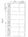
- the PLU file 26 comprises a PLU table and a classified total file, as shown in Fig. 2. These PLU table and classified total file are constituted by a master file MF for storing article data of fixed articles and a temporary file TF for storing article data of temporary articles.
- the PLU table stores article data for each article of trade, and comprises columns for article codes, classified codes, unit prices, article names, attributes, and a spare column.
- the classified total file comprises columns for a quantity and sums of money with respect to the article code.
- FIG. 3 is a block diagram of one example of the POS terminal embodying the present invention
- Fig. 4 is a perspective view thereof.
- This POS terminal comprises a main control unit MCU, an input/output (I/O) control unit IOC, and an I/O unit IO.
- I/O input/output
- I/O unit IO input/output unit
- the microprocessor unit in the main control unit MCU executes a main program for carrying out a primary process of the POS terminal
- the microprocessor unit in the I/O control unit IOC executes an input/output control subprogram for carrying out the I/O control including communication control for the controller 2.
- the main control unit MCU executes such processes as an analysis of the data through the I/O control unit IOC, a classified total, and registration.
- This main control unit MCU comprises a microprocessor 110 for executing the program, a read only memory (ROM) 111 for storing the programs and parameters needed to carry out the process of the microprocessor 110, a random access memory (RAM) 112 for storing the data needed for the operation of the microprocessor 110, the registration file, and the classified total file, etc., a direct memory access (DMA) controller 113 for executing direct access for the RAM 112 according to the instruction received, and a bus for connecting the microprocessor 110, the ROM 111, the RAM 112, and the DMA controller 113, etc., to one another.
- DMA direct memory access
- the I/O controller IOC executes key inputting, a displaying subroutine, scanning, editing, printing, and line controlling, etc., according to the instructions received from the main control unit MCU.
- This I/O controller IOC comprises a microprocessor 120 for executing the programs for carrying out the I/O processing, a ROM 121 for storing an I/O device controlling subprogram having the functions for communicating with the controller 2 to receive the content of the PLU table 26 and for carrying out the printing by the printer 132, and the parameters, etc., a RAM 122 for storing the data needed for the operation of the microprocessor 120, a DMA controller 123 for executing the direct access for the RAM 122 according to the instructions received, an interface 124 connecting between the main control unit MCU and a bus 125 of the I/O control unit IOC and communicating data and commands between the main control unit MCU and the I/O control unit IOC, and a bus 125 for communicating data and commands between the microprocessor 120, the ROM 121, the RAM
- the I/O unit IO comprises a key input portion 130 including a keyboard 130a and a mode selection key 130b for maintenance, etc., a key control portion 131 for detecting operation of the key input'portion 130 and sending the input data to the bus 125, a printer 132, a printer control portion 133 for controlling the printer 132, a drawer 134 for storing cash, a display 135 for displaying input data and the result of a process, a port 136 for connecting the drawer 134 and the display 135 to the bus 125, a scanner (bar code reader) 137 for inputting data by scanning the bar code affixed to an article, such as JAN (Japanese article number), UPC (Universal product code), or EAN (European article number) etc., a scanner interface 138 for sending the data input from the scanner 137 to the bus 125, and a line interface 139 for communicating with the controller 2 via the line 3.
- a key input portion 130 including a keyboard 130a and a mode selection key 130b for
- the process of the function indicated by the key input portion 130 is executed by the main control unit MCU, and the process for the fundamental I/O control is executed by the I/O control unit IOC. That is, the main control unit MCU and the I/O control unit IOC can access the respective other side RAM 112 and 122 via the interface 124 via the other side DMA controller 113 and 123 respectively.
- the ROM 111 of the main control unit MCU stores the main program for the process needed to carry out the primary operations of the POS terminal, such as the classified total process, register process, price look-up process, and exact calculation process, etc.
- the ROM 121 of the I/O control unit IOC stores the input/output control subprogram for controlling the I/O device. Accordingly, the main control unit MCU executes the process for the POS functions, and the I/O control unit IOC executes the process for the I/O control.
- the operations of the present POS system i.e., the PLU table inquiry operation, the PLU data changing operation, the PLU data creating (new registration) operation, and the emergency PLU data creating operation will now described in sequence with reference to the flowcharts.
- the PLU table inquiry operation processes inquiries from the POS terminals 1 regarding article data, such as price, to the controller 2.
- the PLU data changing operation processes changes in the PLU data stored in the PLU table for new data from the POS terminals 1, and the PLU data creating operation processes the registration of new PLU table data sent from the POS terminals 1 into the PLU table.
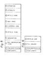
- Figures 5 and 6 show an example of the format of the text transmitted between the controller 2 and each POS terminal 1, respectively.
- the text of Fig. 5 comprises the following information sections wherein the information is given upon inquiry. That is;
- the POS terminal 1 instructs the controller 2 to designate a change, creation, erasure or classification of the PLU data by this text
- both 5 and 6 are input from the POS terminal and used in the case of texts (i), (ii) or (iii)
- Figure 6 shows a format of the text for sending a PLU table inquiry demand from the POS terminal 1.
- This text comprises,
- Figure 7 is a flowchart showing the process of the PLU table inquiry operation.
- This PLU inquiry demand text includes the text identification data indicating a PLU table inquiry and the input article code.
- the text from the POS terminal 1 is received by the line sub CPU 23, and transmitted to the main CPU 21.
- the main CPU 21 analyzes the received text by executing the text analyzing task to distinguish the process demanded.
- the demanded process is the PLU table inquiry, and therefore the main CPU 21 executes a search of the PLU file 26.
- the temporary file TF is searched, and if the article information is not in the temporary file, then the master file MF is searched. If the article information of the demanded article code is registered in either the temporary file TF or the main file MF, that main CPU 21 compiles the PLU response (OK) text including the classified code, the unit price, the article name, the bank number, and the address, etc., in the text format shown in Fig. 5, and sends it to the POS terminal 1 via the line sub CPU 23.
- PLU response OK
- the main CPU 21 compiles a non-registration text in the format shown in Fig. 5, and transmits it to the POS terminal 1 via the line sub CPU 23.
- the PLU response text is received in the POS terminal 1 via the line interface 139, transmitted to the microprocessor 110 under the control of the microprocessor 120, and then stored in the sales details area of the RAM 112.
- the data stored in the sales details area is then transmitted to the microprocessor 120 as display and print data.
- the SUM key at the keyboard is operated, this is acknowledged by the microprocessor 110, via the microprocessor 120, and the summing of the data stored in the sales details area of the RAM 112, is then executed, and the result displayed and printed by the display 135 and the printer 132 respectively.
- the microprocessor 110 compiles a details text containing the content of the sales details area and sends it to the controller 2 via the line interface 134. Accordingly the classified total file of the PLU file 26 is updated by the controller 2.
- the main control unit MCU receives this text via the I/O unit 10 and the I/O control unit IOC, analyses the text to determine that the received text is a non-registration text, and then displays that fact on the display 135.
- FIG. 8 is the flowchart showing the PLU data changing operation.
- the mode selection key 130b in the key input portion 130 of the POS terminal 1 is set to the PLU data changing position, and the article code is input by the keyboard 130a or the scanner 137. Accordingly, the main control unit MCU compiles the maintenance demand text in which the text identification data G) is "maintenance demand", the indication 4 is "change”, and the article code is written, then sends it to the controller 2 via the I/O control unit IOC, the I/O unit IO, and the line 3.
- the main CPU 21 analyses the content of the text to determine that the received text is a maintenance demand text. Then the main CPU 21 searches for the article information of the article code contained in the text by using the PLU file 26.
- the main CPU 21 checks that whether or not the article information corresponding to the article code exists. If the information exists, the former data text in the Fig. 5 format, in which the text identification data is "former data" and the former article information such as the unit price and classified code registered in the PLU table is written, is prepared and sent back to the POS terminal 1 from which the maintenance demand text was received.
- the main CPU 21 prepares a non-registration text in which the text identification data is "non-registration: and the unit prices and the classified code, etc., are set to the dummy data "0", then sends it to the POS terminal 1.
- the main control unit MCU analyses the text. As the result of the analysis, when the text is determined to be the former data text, that main control unit MCU displays the content of the former data of the article on the display 135 via the I/O control unit IOC. Then the new data to be entered is input by the key input portion 130. The main control unit MCU then prepares the new data text in which the text identification data is "new data" and containing the new article information such as the unit price, and sends the text to the controller 2 via the I/O control unit IOC, the I/O unit IO and the line 3.
- the text is determined to be a non-registration text, that fact is displayed on the display 135 and, if necessary, the registration (data creation) described hereinafter is executed.
- the received new data text is transmitted to the main CPU 21 via the line sub CPU 23.
- the main CPU 21 then rewrites the former article information in the PLU table as the new article information indicated by the POS terminal 1. Accordingly, for that and all subsequent PLU inquiry demands regarding that article, each POS terminal 1 is informed of the new data.
- the process finish text in which the text identification data is "process finish” is sent to the POS terminal. Conversely, if the data changing process is not finished, the process NG text in which the text identification data is "process NG” is prepared and sent to the POS terminal 1.
- the controller 2 prepares and sends a busy text in which the text identification data is "busy" to the POS terminal 1.
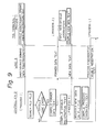
- FIG. 9 is a flowchart showing the PLU table new registration operation.
- the mode selection key 130b of the key input portion 130 is set to the PLU table new registration position. Then the article code to be registered is input by the keyboard.
- the main control unit MCU prepares the maintenance demand text in the Fi g . 5 format in which the text identification data 3 is "maintenance demand text", the indication 4 is "creation”, and the article codes is written; sends this text to the controller 2 via the I/O control unit IOC, I/O unit IO and the line 3.
- the received text is analyzed by the main CPU 21.
- the main CPU determines that the received vext is the maintenance demand text regarding a new registration, then checks whether or not the article code included in the text exists in the PLU file 26. If not, the former data text regarding the article to be newly registered is prepared. In this case, since the former data does not exist, dummy data is used for the classified code, the unit prince, the article name, and attribute, etc., and the memory bank number and the memory address of the temporary file assigned to be registered by the POS terminal are used as the bank number and address.
- the main CPU 21 sends this former data text to the POS terminal via the line sub CPU 23 and line 3.
- the main CPU 21 prepares a double registration text in which the text identification data C3) is "double registration", and sends this text to the POS terminal 1.
- the received text is transmi tted to the main control unit MCU via the line interface 139 and the I/O control unit IOC.
- the microprocessor 110 analyses this text to determine that the text is the former data text, then begins to prepare the new data text.
- the microprocessor 110 informs the microprocessor 120 via the interface 124 that the article information such as class and price has been input by the key input portion 130.
- the microprocessor 120 receives the article information input by the key input portion 130 and transmits the new data text to the controller 2.
- the received text is transmitted to the main CPU 21, analyzed, and determined to be the new data text. Then the main CPU registers the new article information such as the article code, classified code, and unit price of the new data text to the address and the bank number of the temporary file TF included in the new data text. The main CPU 21 also prepares a file maintenance process finish (OK) text and sends the text to the POS terminal.
- a file maintenance process finish OK
- the microprocessor 120 In the POS terminal, when the file maintenance process finish (OK) text is received via the line interface 139, the microprocessor 120 is informed of this. The microprocessor 120 then informs the microprocessor 110, and the microprocessor 110 accordingly finishes the new registration operation.
- Figure 10 is a flowchart showing the emergency registration operation.
- the controller 2 sends the non-registration text to the POS terminal 1.
- the microprocessor 110 at the POS terminal analyses the received text, determines that it is a non-registration text, and then executes the emergency registration operation. That is, the file maintenance demand text regarding the new registration, the same as the text described in the process H, is prepared and sent to the controller 2. Then the aforementioned processes I, J, and K are executed, and the emergency registration process is finished.
- the processing mode of the controller 2 comprises a queue 1 (PLU table inquiry demand process), queue 2 (file maintenance demand process), and queue 3 (total demand process), and these queues l, 2, and 3 are given priority in that sequence; that is queue 1 has first priority. Accordingly, if a queue 1 demand is generated while the processes queue 2 or 3 are being executed, the queue 2 or 3 process is temporarily interrupted and the queue 1 process is executed. The queue 2 or 3 process is resumed after the queue 1 process is completed.
- the system of the present invention is not limited to this operation. Namely, it is possible to change the information stored in all of the POS terminals from by using an individual POS terminal. That is, when wishing to change, for example, the rate of reduction in price stored in each POS terminal, or to indicate a commercial message to be printed on the receipt, this data can be sent to the controller 2 from one POS terminal, and the data then sent to all of the other POS terminals from the controller 2 thereby the former data in all POS terminals is rewritten as the new data.
- the backup controller 2' constantly intercepts communications between the controller 2 and the POS terminals 1 by means of the polling supervisory portion 24, thereby executing a supervisory function over the condition of the controller 2. This interception enables the backup controller 2' to update it's PLU table in the same way as the controller 2. Therefore, when the controller 2 malfunctions the backup controller 2' executes the processes for the PLU inquiry demand, etc., in place of the controller 2, using a PLU table storing the most newly updated data.
Abstract
Description
- The present invention relates to a point of sales (POS) system in which a POS terminal can obtain data such as article prices from a central computer having a price look-up (PLU) table storing such article '-data. More particularly, it relates to a POS system in which article data stored in the PLU table can be immediately and easily updated from individual POS terminals. The POS system of the present invention can be used for sales management in, for example, a department store or supermarket.
- A POS system is generally used for sales management in department stores and supermarkets, etc. In this system, the central computer is disposed at an office remote from the POS terminals disposed at each sales counter. This arrangement enables accurate cash management at the time and point of sales, the collection of sales data, and the collection of proceeds data relative to each article sold, etc., to be carried out in real time by the central computer.
- In a prior POS system, each POS terminal holds a PLU table storing article data such as unit costs per article, article name, and the classification code for each article (article code). The article code of each article is input to the POS terminal through a keyboard or scanner (bar code reader) provided at the POS terminal and thus calculation of the total proceeds, and the collection of proceeds data, etc., are performed by using the PLU table.
- On the other hand, article data such as the unit cost of the article stored in the PLU table of each POS terminal is often changed on a daily basis, or even during the course of business. Therefore, it is necessary to transmit the article data in the PLU table for each day to each POS terminal, from the central computer, prior to the start of business, to update each day the content of the PLU table in each POS terminal. However, the transmission of the article data to each POS terminal every day takes a long time and involves a complicated procedure. In particular, when the necessity to update the PLU table, for example, to change unit costs, -correct erroneous article data, or register new article data into the PLU table, etc., arises during the course of business, the central computer must correct the data in the PLU table and transmit the corrected data to all of the, POS terminals. However, this operation wastes time, and during that time service at the POS terminals interrupted, with the result that customers must be kept waiting for an inordinate length of time. Therefore, it would be preferable if the updating of the PLU table could be performed immediately from individual POS terminals, and the result of the updating be immediately and simultaneously reflected at all other POS terminals in the POS system.
- Further, to constitute each POS terminal to contain the PLU table greatly increases the cost of the POS system.
- Accordingly, it is desirable to provide an POS system in which the central computer holds the PLU table and each POS terminal obtains article data from the central computer at the time of sale, thereby realizing central control of the management of the PLU table,' enabling updating of the PLU table at the central computer to be immediately and easily performed from individual POS terminals, and the result of such updating to be immediately reflected at all other POS terminals in the POS system.
- According to the fundamental aspect of the present invention, there is provided a point of sales (POS) system comprising a central computer and a plurality of POS terminals connected to the central computer; the central computer including; a look-up table storing article data for each article of trade; means for sending and receiving a test; means for analyzing the received text from the sending and receiving means; means for searching the look-up table according to the result of the analysis by the analyzing means; means for '-compiling a response text according to the findings of the search by the searching means; and means for updating the content of the look-up table according to the result of the analysis by the analyzing means; each of said plurality of POS terminals including; means for sending and receiving a text; means for compiling an inquiry demand text demanding article data for each article of trade in the look-up table; means for compiling an update demand text demanding an update of the content of the look-up table; and means for inputting the updated content of the look-up table; wherein the central computer, in response to the inquiry demand text sent from the POS terminal, analyzes the received text by means of the analyzing means, searches the look-up table by means of the searching means according to the result of the analysis, compiles the response text by means of the response text compiling means according to the findings of the search, and sends back the response text by means of the sending and receiving means to each of plurality of POS terminals, and, the central computer, in response to the update demend text sent from the POS terminals, analyzes the received text by means of the analyzing means, and updates the content of the look-up table to the content designated by the POS terminals by means of the searching means.
- Reference will now be made, by way of example, to the accompanying drawings, in which:
- Fig. 1 shows one example of a POS system embodying the present invention;
- Fig. 2 shows one example of a PLU file provided in the controller;
- Fig. 3 shows one example of a block diagram of the POS terminal embodying the present invention;
- Fig. 4 shows a perspective view of the device shown in Fig. 3;
- 1- Fig. 5 and Fig. 6 show one example of the format of the text transmitted between the controller and each POS terminal respectively;
- Fig. 7 is a flowchart showing the PLU table inquiry operation;
- Fig. 8 is a flowchart showing the PLU table changing operation;
- Fig. 9 is a flowchart showing the PLU table new registration operation; and
- Fig. 10 is a flowchart showing the emergency registration operation.
- Figure 1 shows one example of a POS system embodying the present invention. In Fig. 1, n units of
POS terminals 1 disposed counters are respectively connected to twocontrollers 2 and 2' disposed at an office and acting as central computers via aline 3. The constitution of each of thePOS terminals 1 is the same, as is the constitution of each of thecontrollers 2 and 2'. The controller 2' is utilized as a backup for thecontroller 2. - Each of the
controllers 2 and 2' comprises a main central processing unit (CPU) 21 for processing the task demanded by thePOS terminals 1, aline sub CPU 22 for executing control of theline 3 for thePOS terminals 1, anarithmetic CPU 23 for executing an arithmetic process, a release processing portion for processing a release process when a controller malfunctions, and pollingsupervisory portion 24 for supervising a polling signal generated at the other side controller and checking whether the other side controller is in a normal condition or in a failure condition, etc. Themain CPU 21 holds aPLU file 26. ThePLU file 26 comprises a PLU table and a classified total file, as shown in Fig. 2. These PLU table and classified total file are constituted by a master file MF for storing article data of fixed articles and a temporary file TF for storing article data of temporary articles. - The PLU table stores article data for each article of trade, and comprises columns for article codes, classified codes, unit prices, article names, attributes, and a spare column. The classified total file comprises columns for a quantity and sums of money with respect to the article code.
- Figure 3 is a block diagram of one example of the POS terminal embodying the present invention, and Fig. 4 is a perspective view thereof. This POS terminal comprises a main control unit MCU, an input/output (I/O) control unit IOC, and an I/O unit IO. In this POS terminal of the present invention, the throughout of the POS terminal is increased in comparison with the prior art POS terminal, because the PLU table is provided in the
controller 2. So, thePOS terminal 1 contains two microprocessor units to carry out the alloted tasks. That is, the microprocessor unit in the main control unit MCU executes a main program for carrying out a primary process of the POS terminal, and the microprocessor unit in the I/O control unit IOC executes an input/output control subprogram for carrying out the I/O control including communication control for thecontroller 2. - As shown in Fig. 3, the main control unit MCU executes such processes as an analysis of the data through the I/O control unit IOC, a classified total, and registration. This main control unit MCU comprises a
microprocessor 110 for executing the program, a read only memory (ROM) 111 for storing the programs and parameters needed to carry out the process of themicroprocessor 110, a random access memory (RAM) 112 for storing the data needed for the operation of themicroprocessor 110, the registration file, and the classified total file, etc., a direct memory access (DMA)controller 113 for executing direct access for theRAM 112 according to the instruction received, and a bus for connecting themicroprocessor 110, the ROM 111, theRAM 112, and theDMA controller 113, etc., to one another. - The I/O controller IOC executes key inputting, a displaying subroutine, scanning, editing, printing, and line controlling, etc., according to the instructions received from the main control unit MCU. This I/O controller IOC comprises a
microprocessor 120 for executing the programs for carrying out the I/O processing, aROM 121 for storing an I/O device controlling subprogram having the functions for communicating with thecontroller 2 to receive the content of the PLU table 26 and for carrying out the printing by theprinter 132, and the parameters, etc., aRAM 122 for storing the data needed for the operation of themicroprocessor 120, aDMA controller 123 for executing the direct access for theRAM 122 according to the instructions received, aninterface 124 connecting between the main control unit MCU and abus 125 of the I/O control unit IOC and communicating data and commands between the main control unit MCU and the I/O control unit IOC, and abus 125 for communicating data and commands between themicroprocessor 120, theROM 121, theRAM 122, theDMA controller 123, and theinterface 124. Themicroprocessors interface 124, and theDMA controllers RAM 122 and 111 of the IOC and MCU units. - The I/O unit IO comprises a
key input portion 130 including a keyboard 130a and amode selection key 130b for maintenance, etc., akey control portion 131 for detecting operation of thekey input'portion 130 and sending the input data to thebus 125, aprinter 132, aprinter control portion 133 for controlling theprinter 132, adrawer 134 for storing cash, adisplay 135 for displaying input data and the result of a process, aport 136 for connecting thedrawer 134 and thedisplay 135 to thebus 125, a scanner (bar code reader) 137 for inputting data by scanning the bar code affixed to an article, such as JAN (Japanese article number), UPC (Universal product code), or EAN (European article number) etc., ascanner interface 138 for sending the data input from thescanner 137 to thebus 125, and aline interface 139 for communicating with thecontroller 2 via theline 3. - In this POS terminal, the process of the function indicated by the
key input portion 130 is executed by the main control unit MCU, and the process for the fundamental I/O control is executed by the I/O control unit IOC. That is, the main control unit MCU and the I/O control unit IOC can access the respectiveother side RAM interface 124 via the otherside DMA controller ROM 121 of the I/O control unit IOC stores the input/output control subprogram for controlling the I/O device. Accordingly, the main control unit MCU executes the process for the POS functions, and the I/O control unit IOC executes the process for the I/O control. - The operations of the present POS system, i.e., the PLU table inquiry operation, the PLU data changing operation, the PLU data creating (new registration) operation, and the emergency PLU data creating operation will now described in sequence with reference to the flowcharts. The PLU table inquiry operation processes inquiries from the
POS terminals 1 regarding article data, such as price, to thecontroller 2. The PLU data changing operation processes changes in the PLU data stored in the PLU table for new data from thePOS terminals 1, and the PLU data creating operation processes the registration of new PLU table data sent from thePOS terminals 1 into the PLU table. - Figures 5 and 6 show an example of the format of the text transmitted between the
controller 2 and eachPOS terminal 1, respectively. The text of Fig. 5 comprises the following information sections wherein the information is given upon inquiry. That is; - ① item length
- ② item identification
- text identification data
- (one of the following may be selected)
- (i) maintenance demand (from the
POS terminal 1 to the controller 2) - (ii) former data (from the
controller 2 to the POS terminal 1) - (iii) new data (from the
POS terminal 1 to the controller 2) - (iv) non-registration (from the
controller 2 to thePOS terminal 1. Thecontroller 2 sends this text to thePOS terminal 1 when the article code indicated by the POS terminal does not exist in the PLU table 26.) - (v) double registration (from the
controller 2 to thePOS terminal 1. thecontroller 2 sends this text to thePOS terminal 1 when the article code indicated by the POS terminal for new registration already exists in the PLU table.) - (vi) busy (from the
controller 2 to the POS terminal 1) - (vii) process finish (OK) (from the
controller 2 to the POS terminal 1) - (viii) process NG (from the
controller 2 to the POS terminal 1)- ④ designation
- the
POS terminal 1 instructs thecontroller 2 to designate a change, creation, erasure or classification of the PLU data by this text - ⑤ article code
- classified code
- both ⑤ and ⑥ are input from the POS terminal and used in the case of texts (i), (ii) or (iii)
- ⑦ unit price
- ⑧ article name
- both ⑦ and ⑧ are included in the text of (ii) or (iii)
- ⑨ attribute
- ⑩ separation
- Figure 6 shows a format of the text for sending a PLU table inquiry demand from the
POS terminal 1. This text comprises, - ① item length
- ② item identification
- PLU table inquiry (as the text identification data)
- article code.
- Figure 7 is a flowchart showing the process of the PLU table inquiry operation.
- When the article code is input by the
key input portion 130 or thescanner 137 in accordance with the sale of articles, that article code is sent to the I/O control unit IOC and stored in theRAM 122. Themicroprocessor 110 is then informed of the input of the article code, by themicroprocessor 120, through theinterface 124, whereby themicroprocessor 110 compiles the PLU inquiry demand test shown in Fig. 6 on the basis of the article code stored in theRAM 122, and sends that text to thecontroller 2 via theline interface 139. This PLU inquiry demand text includes the text identification data indicating a PLU table inquiry and the input article code. - In the
controller 2, the text from thePOS terminal 1 is received by theline sub CPU 23, and transmitted to themain CPU 21. Themain CPU 21 analyzes the received text by executing the text analyzing task to distinguish the process demanded. In this case the demanded process is the PLU table inquiry, and therefore themain CPU 21 executes a search of thePLU file 26. First, the temporary file TF is searched, and if the article information is not in the temporary file, then the master file MF is searched. If the article information of the demanded article code is registered in either the temporary file TF or the main file MF, thatmain CPU 21 compiles the PLU response (OK) text including the classified code, the unit price, the article name, the bank number, and the address, etc., in the text format shown in Fig. 5, and sends it to thePOS terminal 1 via theline sub CPU 23. - On the other hand, if the article information of the demanded article code is not registered in the files TF and MF, the
main CPU 21 compiles a non-registration text in the format shown in Fig. 5, and transmits it to thePOS terminal 1 via theline sub CPU 23. - The PLU response text is received in the
POS terminal 1 via theline interface 139, transmitted to themicroprocessor 110 under the control of themicroprocessor 120, and then stored in the sales details area of theRAM 112. The data stored in the sales details area is then transmitted to themicroprocessor 120 as display and print data. When the SUM key at the keyboard is operated, this is acknowledged by themicroprocessor 110, via themicroprocessor 120, and the summing of the data stored in the sales details area of theRAM 112, is then executed, and the result displayed and printed by thedisplay 135 and theprinter 132 respectively. At the same time, themicroprocessor 110 compiles a details text containing the content of the sales details area and sends it to thecontroller 2 via theline interface 134. Accordingly the classified total file of thePLU file 26 is updated by thecontroller 2. - On the other hand, when the POS terminal receives the PLU response text bearing the non-registration indication, the main control unit MCU receives this text via the I/
O unit 10 and the I/O control unit IOC, analyses the text to determine that the received text is a non-registration text, and then displays that fact on thedisplay 135. - Figure 8 is the flowchart showing the PLU data changing operation.
- First, the mode selection key 130b in the
key input portion 130 of thePOS terminal 1 is set to the PLU data changing position, and the article code is input by the keyboard 130a or thescanner 137. Accordingly, the main control unit MCU compiles the maintenance demand text in which the text identification data G) is "maintenance demand", theindication ④ is "change", and the article code is written, then sends it to thecontroller 2 via the I/O control unit IOC, the I/O unit IO, and theline 3. - In the
controller 2, when the text is received via theline sub CPU 23, themain CPU 21 analyses the content of the text to determine that the received text is a maintenance demand text. Then themain CPU 21 searches for the article information of the article code contained in the text by using thePLU file 26. - That is, the
main CPU 21 checks that whether or not the article information corresponding to the article code exists. If the information exists, the former data text in the Fig. 5 format, in which the text identification data is "former data" and the former article information such as the unit price and classified code registered in the PLU table is written, is prepared and sent back to thePOS terminal 1 from which the maintenance demand text was received. - On the other hand, if the article information does not exist because of, for example, an input error at the
POS terminal 1, themain CPU 21 prepares a non-registration text in which the text identification data is "non-registration: and the unit prices and the classified code, etc., are set to the dummy data "0", then sends it to thePOS terminal 1. - In the
POS terminal 1, when the text from thecontroller 2 is received, it is transmitted to the main control unit MCU via the I/O unit 10 and the I/O control unit IOC. The main control unit MCU analyses the text. As the result of the analysis, when the text is determined to be the former data text, that main control unit MCU displays the content of the former data of the article on thedisplay 135 via the I/O control unit IOC. Then the new data to be entered is input by thekey input portion 130. The main control unit MCU then prepares the new data text in which the text identification data is "new data" and containing the new article information such as the unit price, and sends the text to thecontroller 2 via the I/O control unit IOC, the I/O unit IO and theline 3. - On the other hand, if the text is determined to be a non-registration text, that fact is displayed on the
display 135 and, if necessary, the registration (data creation) described hereinafter is executed. - In the
controller 2, the received new data text is transmitted to themain CPU 21 via theline sub CPU 23. Themain CPU 21 then rewrites the former article information in the PLU table as the new article information indicated by thePOS terminal 1. Accordingly, for that and all subsequent PLU inquiry demands regarding that article, eachPOS terminal 1 is informed of the new data. - When the data changing process is finished, the process finish text in which the text identification data is "process finish" is sent to the POS terminal. Conversely, if the data changing process is not finished, the process NG text in which the text identification data is "process NG" is prepared and sent to the
POS terminal 1. - In addition, if the
controller 2 is busy when thePOS terminal 1 sends the maintenance demand text, thecontroller 2 prepares and sends a busy text in which the text identification data is "busy" to thePOS terminal 1. - Figure 9 is a flowchart showing the PLU table new registration operation.
- In the
POS terminal 1, the mode selection key 130b of thekey input portion 130 is set to the PLU table new registration position. Then the article code to be registered is input by the keyboard. The main control unit MCU prepares the maintenance demand text in the Fig. 5 format in which thetext identification data ③ is "maintenance demand text", theindication ④ is "creation", and the article codes is written; sends this text to thecontroller 2 via the I/O control unit IOC, I/O unit IO and theline 3. - In the
controller 2, the received text is analyzed by themain CPU 21. The main CPU determines that the received vext is the maintenance demand text regarding a new registration, then checks whether or not the article code included in the text exists in thePLU file 26. If not, the former data text regarding the article to be newly registered is prepared. In this case, since the former data does not exist, dummy data is used for the classified code, the unit prince, the article name, and attribute, etc., and the memory bank number and the memory address of the temporary file assigned to be registered by the POS terminal are used as the bank number and address. Themain CPU 21 sends this former data text to the POS terminal via theline sub CPU 23 andline 3. - Conversely, if the article code already exists in the
PLU file 26, themain CPU 21 prepares a double registration text in which the text identification data C3) is "double registration", and sends this text to thePOS terminal 1. - In the POS terminal, the received text is transmi tted to the main control unit MCU via the
line interface 139 and the I/O control unit IOC. In the main control unit MCU, themicroprocessor 110 analyses this text to determine that the text is the former data text, then begins to prepare the new data text. - That is, first, the
microprocessor 110 informs themicroprocessor 120 via theinterface 124 that the article information such as class and price has been input by thekey input portion 130. When the article information input by thekey input portion 130 is received by themicroprocessor 120, the input article information stored in theRAM 122 is transmitted to theRAM 112 via theinterface 124 through theDMAC microprocessor 110 is informed of this. Themicroprocessor 110 prepares the new data text by inserting the new article information into the received former data text, and then sends the new data text to thecontroller 2. - In the
controller 2, the received text is transmitted to themain CPU 21, analyzed, and determined to be the new data text. Then the main CPU registers the new article information such as the article code, classified code, and unit price of the new data text to the address and the bank number of the temporary file TF included in the new data text. Themain CPU 21 also prepares a file maintenance process finish (OK) text and sends the text to the POS terminal. - In the POS terminal, when the file maintenance process finish (OK) text is received via the
line interface 139, themicroprocessor 120 is informed of this. Themicroprocessor 120 then informs themicroprocessor 110, and themicroprocessor 110 accordingly finishes the new registration operation. - Figure 10 is a flowchart showing the emergency registration operation.
- When the article information demanded by the
POS terminal 1 is not registered in the PLU table, thecontroller 2 sends the non-registration text to thePOS terminal 1. Themicroprocessor 110 at the POS terminal analyses the received text, determines that it is a non-registration text, and then executes the emergency registration operation. That is, the file maintenance demand text regarding the new registration, the same as the text described in the process H, is prepared and sent to thecontroller 2. Then the aforementioned processes I, J, and K are executed, and the emergency registration process is finished. - The processing mode of the
controller 2 comprises a queue 1 (PLU table inquiry demand process), queue 2 (file maintenance demand process), and queue 3 (total demand process), and these queues l, 2, and 3 are given priority in that sequence; that isqueue 1 has first priority. Accordingly, if aqueue 1 demand is generated while theprocesses queue queue queue 1 process is executed. Thequeue queue 1 process is completed. - In the aforementioned description, the operation for updating the PLU table in the controller from an individual POS terminal so that the result is reflected at all other POS terminals in the system has been explained. However, the system of the present invention is not limited to this operation. Namely, it is possible to change the information stored in all of the POS terminals from by using an individual POS terminal. That is, when wishing to change, for example, the rate of reduction in price stored in each POS terminal, or to indicate a commercial message to be printed on the receipt, this data can be sent to the
controller 2 from one POS terminal, and the data then sent to all of the other POS terminals from thecontroller 2 thereby the former data in all POS terminals is rewritten as the new data. - The backup controller 2' constantly intercepts communications between the
controller 2 and thePOS terminals 1 by means of the pollingsupervisory portion 24, thereby executing a supervisory function over the condition of thecontroller 2. This interception enables the backup controller 2' to update it's PLU table in the same way as thecontroller 2. Therefore, when thecontroller 2 malfunctions the backup controller 2' executes the processes for the PLU inquiry demand, etc., in place of thecontroller 2, using a PLU table storing the most newly updated data.
Claims (10)
Applications Claiming Priority (2)
| Application Number | Priority Date | Filing Date | Title |
|---|---|---|---|
| JP59280629A JPS61156368A (en) | 1984-12-27 | 1984-12-27 | Control system of table content change |
| JP280629/84 | 1984-12-27 |
Publications (3)
| Publication Number | Publication Date |
|---|---|
| EP0187523A2 true EP0187523A2 (en) | 1986-07-16 |
| EP0187523A3 EP0187523A3 (en) | 1986-11-05 |
| EP0187523B1 EP0187523B1 (en) | 1991-02-27 |
Family
ID=17627709
Family Applications (1)
| Application Number | Title | Priority Date | Filing Date |
|---|---|---|---|
| EP85309443A Expired - Lifetime EP0187523B1 (en) | 1984-12-27 | 1985-12-23 | Pos systems |
Country Status (4)
| Country | Link |
|---|---|
| US (1) | US4841442A (en) |
| EP (1) | EP0187523B1 (en) |
| JP (1) | JPS61156368A (en) |
| DE (1) | DE3581920D1 (en) |
Cited By (12)
| Publication number | Priority date | Publication date | Assignee | Title |
|---|---|---|---|---|
| EP0261650A2 (en) * | 1986-09-22 | 1988-03-30 | Omron Tateisi Electronics Co. | Electronic cash register system with faster access time to price look-up file |
| WO1989009453A1 (en) * | 1988-03-25 | 1989-10-05 | Ncr Corporation | Point of sale file recovery system |
| WO1989009452A1 (en) * | 1988-03-25 | 1989-10-05 | Ncr Corporation | Point of sale system |
| WO1989009443A1 (en) * | 1988-03-25 | 1989-10-05 | Ncr Corporation | Data communications system |
| US4879649A (en) * | 1987-01-28 | 1989-11-07 | Omron Tateisi Electronics Co. | Transaction processing apparatus having PLU function |
| EP0405909A2 (en) * | 1989-06-30 | 1991-01-02 | Ncr International Inc. | Method for updating a checkout system |
| EP0405594A2 (en) * | 1989-06-30 | 1991-01-02 | Sharp Kabushiki Kaisha | Electronic cash register system |
| WO1991007725A2 (en) * | 1989-11-21 | 1991-05-30 | Viata Corporation | Point of sale system |
| US5060185A (en) * | 1988-03-25 | 1991-10-22 | Ncr Corporation | File backup system |
| FR2688078A1 (en) * | 1992-02-28 | 1993-09-03 | Wynid Technologies Sa | Device for processing and transferring plastic money, adaptable to standard computers |
| DE4237467A1 (en) * | 1992-11-06 | 1994-05-11 | Esselte Meto Int Gmbh | Electronic cash register for use in shop - displays prices on main display for customer, and has LCD screen for indicating product information for salesperson |
| WO2000014691A1 (en) * | 1998-09-04 | 2000-03-16 | Seiko Epson Corporation | Pos terminal, method of controlling the pos terminal, pos system using the pos terminal, and information storage medium |
Families Citing this family (29)
| Publication number | Priority date | Publication date | Assignee | Title |
|---|---|---|---|---|
| JPH0663818B2 (en) * | 1986-03-13 | 1994-08-22 | 東京電気株式会社 | Weighing inline system |
| JPH01118956A (en) * | 1987-10-31 | 1989-05-11 | Sharp Corp | Data processor |
| US5179270A (en) * | 1989-05-08 | 1993-01-12 | Spectra-Physics, Inc. | Scanner system interface |
| JPH0833958B2 (en) * | 1989-05-30 | 1996-03-29 | 沖電気工業株式会社 | Customer information processing system |
| JPH03167697A (en) * | 1989-11-27 | 1991-07-19 | Fujitsu Ltd | Totalization system for commercial transaction information |
| US5263164A (en) | 1991-01-09 | 1993-11-16 | Verifone, Inc. | Method and structure for determining transaction system hardware and software configurations |
| GB2254469B (en) * | 1991-03-28 | 1995-05-10 | Barcrest Ltd | Data storage |
| US5424521A (en) * | 1992-03-17 | 1995-06-13 | Checkrobot, Inc. | Article checkout system with price parameter override capacity |
| JPH06131564A (en) * | 1992-10-20 | 1994-05-13 | Matsushita Electric Ind Co Ltd | Electronic cash register |
| JP3064710B2 (en) * | 1992-12-11 | 2000-07-12 | 富士通株式会社 | Data processing system |
| US5707162A (en) * | 1993-11-24 | 1998-01-13 | Seiko Epson Corporation | Modular information processing apparatus |
| JP3399051B2 (en) * | 1993-11-24 | 2003-04-21 | セイコーエプソン株式会社 | POS terminal and its printing device |
| EP0843858A4 (en) * | 1995-04-13 | 2003-06-11 | Eldat Comm Ltd | Sales promotion data processor system and interactive changeable display particularly useful therein |
| JP3267834B2 (en) * | 1995-05-12 | 2002-03-25 | 松下電器産業株式会社 | POS system device |
| US5729696A (en) * | 1995-06-13 | 1998-03-17 | Ncr Corporation | Transaction data recovery system and method |
| JPH0962741A (en) * | 1995-08-25 | 1997-03-07 | Casio Comput Co Ltd | Data processing method of data communication system |
| US5797131A (en) * | 1995-09-21 | 1998-08-18 | Ncr Corporation | Electronic price label support method |
| US7555458B1 (en) | 1996-06-05 | 2009-06-30 | Fraud Control System.Com Corporation | Method of billing a purchase made over a computer network |
| US20030195848A1 (en) | 1996-06-05 | 2003-10-16 | David Felger | Method of billing a purchase made over a computer network |
| US8229844B2 (en) | 1996-06-05 | 2012-07-24 | Fraud Control Systems.Com Corporation | Method of billing a purchase made over a computer network |
| US5918212A (en) * | 1997-07-29 | 1999-06-29 | Ncr Corporation | Electronic price label price synchronization system and method |
| US6275200B1 (en) * | 1997-12-17 | 2001-08-14 | Lacerta Enterprises, Inc. | Method and apparatus for a transparent network guest controller |
| JP3013840B1 (en) * | 1998-09-01 | 2000-02-28 | 日本電気株式会社 | Multiple Price Lookup Maintenance Schemes and Methods |
| US6510989B1 (en) | 2000-01-04 | 2003-01-28 | International Business Machines Corporation | Price check assistant |
| KR100366311B1 (en) * | 2000-02-25 | 2002-12-31 | 이은정 | A direct transaction information service system by automatic crossing and out-calling both side directions communication and a method combining ars telecommunication system with network |
| US7472394B1 (en) * | 2000-07-07 | 2008-12-30 | Paymentech, L.P. | System and method for programming point of sale devices |
| US7668740B1 (en) * | 2000-09-22 | 2010-02-23 | Ita Software, Inc. | Method, system, and computer program product for interfacing with information sources |
| KR100426388B1 (en) * | 2001-06-29 | 2004-04-08 | 세기정보통신(주) | Method and System that perform Electronic Commerce using POS(Point Of Sales) System |
| KR20030068513A (en) * | 2003-07-24 | 2003-08-21 | 주식회사 신흥포스 | Pos management system and data processing method thereof |
Citations (3)
| Publication number | Priority date | Publication date | Assignee | Title |
|---|---|---|---|---|
| US3573739A (en) * | 1968-04-22 | 1971-04-06 | Autolectron Corp | Automatic registration system |
| US3596256A (en) * | 1969-08-08 | 1971-07-27 | Pitney Bowes Alpex | Transaction computer system having multiple access stations |
| JPS592175A (en) * | 1982-06-29 | 1984-01-07 | Fujitsu Ltd | Price change controlling system |
Family Cites Families (5)
| Publication number | Priority date | Publication date | Assignee | Title |
|---|---|---|---|---|
| JPS5282049A (en) * | 1975-12-27 | 1977-07-08 | Fujitsu Ltd | Control system for information alternation of terminal equipment |
| JPS52153642A (en) * | 1976-06-16 | 1977-12-20 | Tokyo Electric Co Ltd | Unit price preset unit for electronic register |
| JPS5833592B2 (en) * | 1977-09-28 | 1983-07-20 | オムロン株式会社 | Data transmission error handling method |
| JPS57773A (en) * | 1980-06-04 | 1982-01-05 | Fujitsu Ltd | Data conversion system of distribution system |
| JPS57197642A (en) * | 1981-05-29 | 1982-12-03 | Sharp Corp | Information transmitting system |
-
1984
- 1984-12-27 JP JP59280629A patent/JPS61156368A/en active Granted
-
1985
- 1985-12-23 EP EP85309443A patent/EP0187523B1/en not_active Expired - Lifetime
- 1985-12-23 DE DE8585309443T patent/DE3581920D1/en not_active Expired - Fee Related
- 1985-12-27 US US06/813,951 patent/US4841442A/en not_active Expired - Fee Related
Patent Citations (3)
| Publication number | Priority date | Publication date | Assignee | Title |
|---|---|---|---|---|
| US3573739A (en) * | 1968-04-22 | 1971-04-06 | Autolectron Corp | Automatic registration system |
| US3596256A (en) * | 1969-08-08 | 1971-07-27 | Pitney Bowes Alpex | Transaction computer system having multiple access stations |
| JPS592175A (en) * | 1982-06-29 | 1984-01-07 | Fujitsu Ltd | Price change controlling system |
Non-Patent Citations (3)
| Title |
|---|
| IBM TDB vol.26 no.3A August 83 page 1202 Strole "Store System with distributed price look-up function * |
| PATENT ABSTRACTS OF JAPAN, vol. 8, no. 86 (P-269)[1523], 19th April 1984; & JP-A-59 002 175 (FUJITSU K.K.) 07-01-1984 * |
| PATENTS ABSTRACTS OF JAPAN, vol. 8, no. 86 (P-269)[1523], 19th April 1984; & JP - A - 59 2175 (FUJITSU K.K.) 07-01-1984 * |
Cited By (19)
| Publication number | Priority date | Publication date | Assignee | Title |
|---|---|---|---|---|
| EP0261650A3 (en) * | 1986-09-22 | 1989-10-25 | Omron Tateisi Electronics Co. | Electronic cash register system with faster access time to price look-up file |
| EP0261650A2 (en) * | 1986-09-22 | 1988-03-30 | Omron Tateisi Electronics Co. | Electronic cash register system with faster access time to price look-up file |
| US4879649A (en) * | 1987-01-28 | 1989-11-07 | Omron Tateisi Electronics Co. | Transaction processing apparatus having PLU function |
| US5060185A (en) * | 1988-03-25 | 1991-10-22 | Ncr Corporation | File backup system |
| WO1989009453A1 (en) * | 1988-03-25 | 1989-10-05 | Ncr Corporation | Point of sale file recovery system |
| WO1989009452A1 (en) * | 1988-03-25 | 1989-10-05 | Ncr Corporation | Point of sale system |
| WO1989009443A1 (en) * | 1988-03-25 | 1989-10-05 | Ncr Corporation | Data communications system |
| US5313664A (en) * | 1988-03-25 | 1994-05-17 | Ncr Corporation | Point of sale system having backup file device |
| EP0405594A3 (en) * | 1989-06-30 | 1993-03-03 | Sharp Kabushiki Kaisha | Electronic cash register system |
| EP0405909A3 (en) * | 1989-06-30 | 1993-02-24 | Ncr Corporation | Method for updating a checkout system |
| EP0405594A2 (en) * | 1989-06-30 | 1991-01-02 | Sharp Kabushiki Kaisha | Electronic cash register system |
| EP0405909A2 (en) * | 1989-06-30 | 1991-01-02 | Ncr International Inc. | Method for updating a checkout system |
| WO1991007725A3 (en) * | 1989-11-21 | 1991-06-27 | Viata Corp | Point of sale system |
| WO1991007725A2 (en) * | 1989-11-21 | 1991-05-30 | Viata Corporation | Point of sale system |
| FR2688078A1 (en) * | 1992-02-28 | 1993-09-03 | Wynid Technologies Sa | Device for processing and transferring plastic money, adaptable to standard computers |
| DE4237467A1 (en) * | 1992-11-06 | 1994-05-11 | Esselte Meto Int Gmbh | Electronic cash register for use in shop - displays prices on main display for customer, and has LCD screen for indicating product information for salesperson |
| DE4237467C2 (en) * | 1992-11-06 | 2001-02-01 | Meto International Gmbh | POS for sales outlets |
| WO2000014691A1 (en) * | 1998-09-04 | 2000-03-16 | Seiko Epson Corporation | Pos terminal, method of controlling the pos terminal, pos system using the pos terminal, and information storage medium |
| US6845363B1 (en) | 1998-09-04 | 2005-01-18 | Seiko Epson Corporation | POS terminal, method of controlling the POS terminal, POS system using the POS terminal, and information storage medium |
Also Published As
| Publication number | Publication date |
|---|---|
| DE3581920D1 (en) | 1991-04-04 |
| EP0187523B1 (en) | 1991-02-27 |
| JPH0156438B2 (en) | 1989-11-30 |
| US4841442A (en) | 1989-06-20 |
| JPS61156368A (en) | 1986-07-16 |
| EP0187523A3 (en) | 1986-11-05 |
Similar Documents
| Publication | Publication Date | Title |
|---|---|---|
| EP0187523B1 (en) | Pos systems | |
| US4855908A (en) | POS system | |
| US4360872A (en) | Electronic cash register system | |
| US5870716A (en) | Home terminal and shopping system | |
| GB2176921A (en) | Method and system for processing data | |
| EP0239982A2 (en) | Data input device | |
| US4949258A (en) | Transaction processor which derives a commodity code from an article code and stores sales of data of both | |
| JPH07205950A (en) | Portable type label printer device and sale price changing system | |
| JP2893715B2 (en) | Order data processing system | |
| JP2918766B2 (en) | Product sales data processing device | |
| JPH0668794B2 (en) | Electronic cash register | |
| JP3014327B2 (en) | Register device | |
| JP2522531B2 (en) | POS system | |
| KR920004758B1 (en) | Method of discount sale for cash register | |
| JPH079661B2 (en) | Transaction processor | |
| JP3519241B2 (en) | Electronic cash register | |
| JPH08320970A (en) | Commodity sales registering data processing system | |
| JPS61210499A (en) | Pos system | |
| JPH1173468A (en) | Commodity price changing system | |
| JPH071517B2 (en) | POS system | |
| JPH07225880A (en) | Commodity sale register data processor | |
| JPS61221960A (en) | Transaction data processor | |
| JPS5828612B2 (en) | Education mode processing method of data collection system | |
| JPH0670832B2 (en) | POS system | |
| JP2002109644A (en) | Pos system, pos server, store terminal, sales management method and recording medium |
Legal Events
| Date | Code | Title | Description |
|---|---|---|---|
| PUAI | Public reference made under article 153(3) epc to a published international application that has entered the european phase |
Free format text: ORIGINAL CODE: 0009012 |
|
| AK | Designated contracting states |
Kind code of ref document: A2 Designated state(s): DE FR GB |
|
| PUAL | Search report despatched |
Free format text: ORIGINAL CODE: 0009013 |
|
| AK | Designated contracting states |
Kind code of ref document: A3 Designated state(s): DE FR GB |
|
| 17P | Request for examination filed |
Effective date: 19870413 |
|
| 17Q | First examination report despatched |
Effective date: 19890606 |
|
| GRAA | (expected) grant |
Free format text: ORIGINAL CODE: 0009210 |
|
| AK | Designated contracting states |
Kind code of ref document: B1 Designated state(s): DE FR GB |
|
| PGFP | Annual fee paid to national office [announced via postgrant information from national office to epo] |
Ref country code: FR Payment date: 19910308 Year of fee payment: 7 |
|
| ET | Fr: translation filed | ||
| REF | Corresponds to: |
Ref document number: 3581920 Country of ref document: DE Date of ref document: 19910404 |
|
| PGFP | Annual fee paid to national office [announced via postgrant information from national office to epo] |
Ref country code: GB Payment date: 19911210 Year of fee payment: 7 |
|
| PLBE | No opposition filed within time limit |
Free format text: ORIGINAL CODE: 0009261 |
|
| STAA | Information on the status of an ep patent application or granted ep patent |
Free format text: STATUS: NO OPPOSITION FILED WITHIN TIME LIMIT |
|
| 26N | No opposition filed | ||
| PGFP | Annual fee paid to national office [announced via postgrant information from national office to epo] |
Ref country code: DE Payment date: 19920225 Year of fee payment: 7 |
|
| PG25 | Lapsed in a contracting state [announced via postgrant information from national office to epo] |
Ref country code: GB Effective date: 19921223 |
|
| GBPC | Gb: european patent ceased through non-payment of renewal fee |
Effective date: 19921223 |
|
| PG25 | Lapsed in a contracting state [announced via postgrant information from national office to epo] |
Ref country code: FR Effective date: 19930831 |
|
| PG25 | Lapsed in a contracting state [announced via postgrant information from national office to epo] |
Ref country code: DE Effective date: 19930901 |
|
| REG | Reference to a national code |
Ref country code: FR Ref legal event code: ST |