EP0187476B1 - Herstellung von Formteilen aus amorphen Legierungen - Google Patents
Herstellung von Formteilen aus amorphen Legierungen Download PDFInfo
- Publication number
- EP0187476B1 EP0187476B1 EP85308857A EP85308857A EP0187476B1 EP 0187476 B1 EP0187476 B1 EP 0187476B1 EP 85308857 A EP85308857 A EP 85308857A EP 85308857 A EP85308857 A EP 85308857A EP 0187476 B1 EP0187476 B1 EP 0187476B1
- Authority
- EP
- European Patent Office
- Prior art keywords
- amorphous alloy
- powders
- raw material
- powder layer
- shock
- Prior art date
- Legal status (The legal status is an assumption and is not a legal conclusion. Google has not performed a legal analysis and makes no representation as to the accuracy of the status listed.)
- Expired - Lifetime
Links
- 229910000808 amorphous metal alloy Inorganic materials 0.000 title claims description 230
- 238000004519 manufacturing process Methods 0.000 title claims description 13
- 239000000843 powder Substances 0.000 claims description 335
- 230000035939 shock Effects 0.000 claims description 159
- 239000002994 raw material Substances 0.000 claims description 89
- 239000002184 metal Substances 0.000 claims description 78
- 229910052751 metal Inorganic materials 0.000 claims description 77
- 238000000034 method Methods 0.000 claims description 56
- 229910045601 alloy Inorganic materials 0.000 claims description 49
- 239000000956 alloy Substances 0.000 claims description 49
- 239000002245 particle Substances 0.000 claims description 49
- 239000002360 explosive Substances 0.000 claims description 35
- 238000004880 explosion Methods 0.000 claims description 20
- 238000003825 pressing Methods 0.000 claims description 15
- 238000001816 cooling Methods 0.000 claims description 13
- 239000000203 mixture Substances 0.000 claims description 12
- 238000002156 mixing Methods 0.000 claims description 3
- 239000008240 homogeneous mixture Substances 0.000 claims description 2
- 239000011812 mixed powder Substances 0.000 claims 1
- XEEYBQQBJWHFJM-UHFFFAOYSA-N Iron Chemical compound [Fe] XEEYBQQBJWHFJM-UHFFFAOYSA-N 0.000 description 75
- RYGMFSIKBFXOCR-UHFFFAOYSA-N Copper Chemical compound [Cu] RYGMFSIKBFXOCR-UHFFFAOYSA-N 0.000 description 58
- 229910000831 Steel Inorganic materials 0.000 description 57
- 239000010959 steel Substances 0.000 description 57
- 229910052802 copper Inorganic materials 0.000 description 56
- 239000010949 copper Substances 0.000 description 56
- 238000012856 packing Methods 0.000 description 35
- RTAQQCXQSZGOHL-UHFFFAOYSA-N Titanium Chemical compound [Ti] RTAQQCXQSZGOHL-UHFFFAOYSA-N 0.000 description 32
- 239000010936 titanium Substances 0.000 description 31
- 229910052719 titanium Inorganic materials 0.000 description 31
- 239000000126 substance Substances 0.000 description 26
- 239000011888 foil Substances 0.000 description 25
- 229910052742 iron Inorganic materials 0.000 description 24
- PXHVJJICTQNCMI-UHFFFAOYSA-N Nickel Chemical compound [Ni] PXHVJJICTQNCMI-UHFFFAOYSA-N 0.000 description 20
- 238000005192 partition Methods 0.000 description 20
- 238000002474 experimental method Methods 0.000 description 12
- 230000000052 comparative effect Effects 0.000 description 11
- 239000000463 material Substances 0.000 description 10
- 229910052759 nickel Inorganic materials 0.000 description 10
- 239000007787 solid Substances 0.000 description 10
- XUIMIQQOPSSXEZ-UHFFFAOYSA-N Silicon Chemical compound [Si] XUIMIQQOPSSXEZ-UHFFFAOYSA-N 0.000 description 7
- 230000015572 biosynthetic process Effects 0.000 description 7
- 238000005422 blasting Methods 0.000 description 7
- 229910052710 silicon Inorganic materials 0.000 description 7
- 239000010703 silicon Substances 0.000 description 7
- ZOXJGFHDIHLPTG-UHFFFAOYSA-N Boron Chemical compound [B] ZOXJGFHDIHLPTG-UHFFFAOYSA-N 0.000 description 6
- 229910052796 boron Inorganic materials 0.000 description 6
- 230000005291 magnetic effect Effects 0.000 description 6
- 238000009826 distribution Methods 0.000 description 4
- 230000001788 irregular Effects 0.000 description 4
- 150000002739 metals Chemical class 0.000 description 4
- 230000002093 peripheral effect Effects 0.000 description 4
- 239000011800 void material Substances 0.000 description 4
- OKKJLVBELUTLKV-UHFFFAOYSA-N Methanol Chemical compound OC OKKJLVBELUTLKV-UHFFFAOYSA-N 0.000 description 3
- 239000004372 Polyvinyl alcohol Substances 0.000 description 3
- 239000013078 crystal Substances 0.000 description 3
- 238000002425 crystallisation Methods 0.000 description 3
- 230000008025 crystallization Effects 0.000 description 3
- 229920002451 polyvinyl alcohol Polymers 0.000 description 3
- 239000000047 product Substances 0.000 description 3
- 230000000630 rising effect Effects 0.000 description 3
- 229910001369 Brass Inorganic materials 0.000 description 2
- OKTJSMMVPCPJKN-UHFFFAOYSA-N Carbon Chemical compound [C] OKTJSMMVPCPJKN-UHFFFAOYSA-N 0.000 description 2
- 238000002441 X-ray diffraction Methods 0.000 description 2
- 239000010951 brass Substances 0.000 description 2
- 230000008859 change Effects 0.000 description 2
- 229910017052 cobalt Inorganic materials 0.000 description 2
- 239000010941 cobalt Substances 0.000 description 2
- GUTLYIVDDKVIGB-UHFFFAOYSA-N cobalt atom Chemical compound [Co] GUTLYIVDDKVIGB-UHFFFAOYSA-N 0.000 description 2
- 238000005056 compaction Methods 0.000 description 2
- 230000007797 corrosion Effects 0.000 description 2
- 238000005260 corrosion Methods 0.000 description 2
- 238000005474 detonation Methods 0.000 description 2
- 230000000694 effects Effects 0.000 description 2
- 239000012467 final product Substances 0.000 description 2
- 239000007789 gas Substances 0.000 description 2
- 229910002804 graphite Inorganic materials 0.000 description 2
- 239000010439 graphite Substances 0.000 description 2
- 238000011835 investigation Methods 0.000 description 2
- 230000007246 mechanism Effects 0.000 description 2
- 230000000149 penetrating effect Effects 0.000 description 2
- 229920003023 plastic Polymers 0.000 description 2
- 239000004033 plastic Substances 0.000 description 2
- 229920000915 polyvinyl chloride Polymers 0.000 description 2
- 239000004800 polyvinyl chloride Substances 0.000 description 2
- 230000008569 process Effects 0.000 description 2
- 229910052717 sulfur Inorganic materials 0.000 description 2
- NAWXUBYGYWOOIX-SFHVURJKSA-N (2s)-2-[[4-[2-(2,4-diaminoquinazolin-6-yl)ethyl]benzoyl]amino]-4-methylidenepentanedioic acid Chemical compound C1=CC2=NC(N)=NC(N)=C2C=C1CCC1=CC=C(C(=O)N[C@@H](CC(=C)C(O)=O)C(O)=O)C=C1 NAWXUBYGYWOOIX-SFHVURJKSA-N 0.000 description 1
- VYZAMTAEIAYCRO-UHFFFAOYSA-N Chromium Chemical compound [Cr] VYZAMTAEIAYCRO-UHFFFAOYSA-N 0.000 description 1
- 229910000640 Fe alloy Inorganic materials 0.000 description 1
- 229910000997 High-speed steel Inorganic materials 0.000 description 1
- GRYLNZFGIOXLOG-UHFFFAOYSA-N Nitric acid Chemical compound O[N+]([O-])=O GRYLNZFGIOXLOG-UHFFFAOYSA-N 0.000 description 1
- OAICVXFJPJFONN-UHFFFAOYSA-N Phosphorus Chemical compound [P] OAICVXFJPJFONN-UHFFFAOYSA-N 0.000 description 1
- BUGBHKTXTAQXES-UHFFFAOYSA-N Selenium Chemical compound [Se] BUGBHKTXTAQXES-UHFFFAOYSA-N 0.000 description 1
- NINIDFKCEFEMDL-UHFFFAOYSA-N Sulfur Chemical compound [S] NINIDFKCEFEMDL-UHFFFAOYSA-N 0.000 description 1
- QCWXUUIWCKQGHC-UHFFFAOYSA-N Zirconium Chemical compound [Zr] QCWXUUIWCKQGHC-UHFFFAOYSA-N 0.000 description 1
- 230000009471 action Effects 0.000 description 1
- 239000000853 adhesive Substances 0.000 description 1
- 230000001070 adhesive effect Effects 0.000 description 1
- 239000002390 adhesive tape Substances 0.000 description 1
- 230000002411 adverse Effects 0.000 description 1
- 238000013459 approach Methods 0.000 description 1
- 239000011230 binding agent Substances 0.000 description 1
- 230000008033 biological extinction Effects 0.000 description 1
- 229910052799 carbon Inorganic materials 0.000 description 1
- 239000001913 cellulose Substances 0.000 description 1
- 229920002678 cellulose Polymers 0.000 description 1
- 238000006243 chemical reaction Methods 0.000 description 1
- 229910052804 chromium Inorganic materials 0.000 description 1
- 239000011651 chromium Substances 0.000 description 1
- 239000012141 concentrate Substances 0.000 description 1
- 238000007796 conventional method Methods 0.000 description 1
- 230000007547 defect Effects 0.000 description 1
- 230000001419 dependent effect Effects 0.000 description 1
- 230000001066 destructive effect Effects 0.000 description 1
- 239000003792 electrolyte Substances 0.000 description 1
- 230000007613 environmental effect Effects 0.000 description 1
- 239000004744 fabric Substances 0.000 description 1
- 230000005294 ferromagnetic effect Effects 0.000 description 1
- -1 for example Substances 0.000 description 1
- 239000007792 gaseous phase Substances 0.000 description 1
- 239000004519 grease Substances 0.000 description 1
- 238000000227 grinding Methods 0.000 description 1
- 229910052735 hafnium Inorganic materials 0.000 description 1
- VBJZVLUMGGDVMO-UHFFFAOYSA-N hafnium atom Chemical compound [Hf] VBJZVLUMGGDVMO-UHFFFAOYSA-N 0.000 description 1
- 238000010438 heat treatment Methods 0.000 description 1
- 230000006872 improvement Effects 0.000 description 1
- 239000000696 magnetic material Substances 0.000 description 1
- 238000005259 measurement Methods 0.000 description 1
- 229910001092 metal group alloy Inorganic materials 0.000 description 1
- 229910017604 nitric acid Inorganic materials 0.000 description 1
- 230000003287 optical effect Effects 0.000 description 1
- 229910052698 phosphorus Inorganic materials 0.000 description 1
- 239000011574 phosphorus Substances 0.000 description 1
- 238000007747 plating Methods 0.000 description 1
- 238000005498 polishing Methods 0.000 description 1
- 230000000644 propagated effect Effects 0.000 description 1
- 238000010298 pulverizing process Methods 0.000 description 1
- 238000005096 rolling process Methods 0.000 description 1
- 238000007789 sealing Methods 0.000 description 1
- 229910052711 selenium Inorganic materials 0.000 description 1
- 239000011669 selenium Substances 0.000 description 1
- 239000010935 stainless steel Substances 0.000 description 1
- 229910001220 stainless steel Inorganic materials 0.000 description 1
- 239000011593 sulfur Substances 0.000 description 1
- 239000010409 thin film Substances 0.000 description 1
- 229910052723 transition metal Inorganic materials 0.000 description 1
- 150000003624 transition metals Chemical class 0.000 description 1
- 238000004804 winding Methods 0.000 description 1
- 229910052726 zirconium Inorganic materials 0.000 description 1
Images



Classifications
-
- B—PERFORMING OPERATIONS; TRANSPORTING
- B22—CASTING; POWDER METALLURGY
- B22F—WORKING METALLIC POWDER; MANUFACTURE OF ARTICLES FROM METALLIC POWDER; MAKING METALLIC POWDER; APPARATUS OR DEVICES SPECIALLY ADAPTED FOR METALLIC POWDER
- B22F3/00—Manufacture of workpieces or articles from metallic powder characterised by the manner of compacting or sintering; Apparatus specially adapted therefor ; Presses and furnaces
- B22F3/006—Amorphous articles
-
- B—PERFORMING OPERATIONS; TRANSPORTING
- B22—CASTING; POWDER METALLURGY
- B22F—WORKING METALLIC POWDER; MANUFACTURE OF ARTICLES FROM METALLIC POWDER; MAKING METALLIC POWDER; APPARATUS OR DEVICES SPECIALLY ADAPTED FOR METALLIC POWDER
- B22F1/00—Metallic powder; Treatment of metallic powder, e.g. to facilitate working or to improve properties
- B22F1/05—Metallic powder characterised by the size or surface area of the particles
- B22F1/052—Metallic powder characterised by the size or surface area of the particles characterised by a mixture of particles of different sizes or by the particle size distribution
-
- B—PERFORMING OPERATIONS; TRANSPORTING
- B22—CASTING; POWDER METALLURGY
- B22F—WORKING METALLIC POWDER; MANUFACTURE OF ARTICLES FROM METALLIC POWDER; MAKING METALLIC POWDER; APPARATUS OR DEVICES SPECIALLY ADAPTED FOR METALLIC POWDER
- B22F1/00—Metallic powder; Treatment of metallic powder, e.g. to facilitate working or to improve properties
- B22F1/08—Metallic powder characterised by particles having an amorphous microstructure
-
- B—PERFORMING OPERATIONS; TRANSPORTING
- B22—CASTING; POWDER METALLURGY
- B22F—WORKING METALLIC POWDER; MANUFACTURE OF ARTICLES FROM METALLIC POWDER; MAKING METALLIC POWDER; APPARATUS OR DEVICES SPECIALLY ADAPTED FOR METALLIC POWDER
- B22F3/00—Manufacture of workpieces or articles from metallic powder characterised by the manner of compacting or sintering; Apparatus specially adapted therefor ; Presses and furnaces
- B22F3/02—Compacting only
- B22F3/08—Compacting only by explosive forces
-
- B—PERFORMING OPERATIONS; TRANSPORTING
- B22—CASTING; POWDER METALLURGY
- B22F—WORKING METALLIC POWDER; MANUFACTURE OF ARTICLES FROM METALLIC POWDER; MAKING METALLIC POWDER; APPARATUS OR DEVICES SPECIALLY ADAPTED FOR METALLIC POWDER
- B22F2998/00—Supplementary information concerning processes or compositions relating to powder metallurgy
-
- Y—GENERAL TAGGING OF NEW TECHNOLOGICAL DEVELOPMENTS; GENERAL TAGGING OF CROSS-SECTIONAL TECHNOLOGIES SPANNING OVER SEVERAL SECTIONS OF THE IPC; TECHNICAL SUBJECTS COVERED BY FORMER USPC CROSS-REFERENCE ART COLLECTIONS [XRACs] AND DIGESTS
- Y10—TECHNICAL SUBJECTS COVERED BY FORMER USPC
- Y10T—TECHNICAL SUBJECTS COVERED BY FORMER US CLASSIFICATION
- Y10T29/00—Metal working
- Y10T29/49—Method of mechanical manufacture
- Y10T29/49805—Shaping by direct application of fluent pressure
- Y10T29/49806—Explosively shaping
Definitions
- the present invention relates to a method for producing amorphous alloy shaped articles, and more particularly relates to a method for producing amorphous alloy shaped articles, wherein a high-energy shock pressure is applied to a layer of a raw material powder of an amorphous alloy or an atomised alloy produced by rapid cooling and having a hardness and a strength higher than ordinary crystalline alloy powders to press the raw material powders into a compact body.
- amorphous alloy powders means powders consisting of amorphous alloy powders, which are obtained by cooling forcedly a melted alloy at a very high cooling rate of 10 4 106°C/sec, and powders obtained by pulverizing a thin strip, fine wire or thin film, which consists of amorphous alloy and has been produced by the rapid cooling method or other commonly known methods.
- atomized alloy powders which have been obtained by cooling a melted alloy at a very high cooling rate and have a hardness and a strength higher than those of ordinary crystalline alloy powders, are also used.
- a raw material for the production of the amorphous alloy shaped article in the present invention includes amorphous alloy powders and atomized alloy powders.
- Amorphous alloy is generally produced by the above described super rapid cooling method and further by other various methods, such as spatter method, gaseous phase chemical reaction method, metal plating method and the like.
- all the resulting amorphous alloys are thin strip, fine wire and powdery product, and even amorphous ribbons produced by a centrifugal method, a single roll method or the like, having only a thickness of from about several tens pm to about several hundreds pm, in which method a melted amorphous alloy is continuously jetted on a rotating body while cooling the body in order to cool the jetted alloy.
- the thin strip, fine wire and fine powders produced in the same methods as described above have substantially the same thickness as that of the ribbon. Therefore, conventional amorphous alloys have hitherto been used in a very limited use field.
- amorphous alloy shaped articles having a larger size are required, and methods for producing large size amorphous alloy shaped articles have been investigated.
- amorphous alloy has a high hardness, and particularly amorphous alloy is converted into crystalline alloy by heating, and therefore it is very difficult to produce amorphous alloy shaped articles.
- Amorphous alloy powders have a hardness remarkably higher than that of crystalline alloy powders, and unless a shock pressure having an energy high enough to form the powders into a shaped article is uniformly acted upon the amorphous alloy powders, a uniform shaped article can not be obtained. While, when the shock pressure is too high, the resulting amorphous alloy shaped article often contains crystallized portion, cracks, crevices, cavities and the like.
- amorphous alloy powders When amorphous alloy powders are packed in a vessel, voids are always formed between fellow particles. When it is intended to produce a high-density shaped article, the amorphous alloy powders must be plastically deformed by a shock pressure until the voids are extinguished, and further adjacent particles must be closely approached to each other, whereby the alloy powders are monolithically bonded to each other such that the boundary of fellow particles can not be substantially observed even by a microscopic observation. In this treatment, the very high hardness of amorphous alloy hinders the close approaching of adjacent powder particles through the extinction of voids and the bonding of the approached particles. That is, the hardness of a material can be regarded as an indication of the deformability of the material. Because, a material having a higher hardness is more difficult to be deformed, and a material having a lower hardness is more easily deformed.
- Amorphous alloy powders are more difficult to be deformed than conventional crystalline metal powders, and a large shock pressure must be applied to amorphous alloy powders in order to deform them, and it is very difficult to deform particles of amorphous alloy powders and further to approach fellow deformed particles to each other and to bond the approached particles. That is, when amorphous alloy powders are pressed under a very high shock pressure, the alloy powders are easily deformed to extinguish voids between the fel low particles of the powders and to achieve satisfactorily the bonding of the fellow particles.
- an excessively high shock pressure applied to amorphous alloy powders not only acts to extinguish voids between the fellow particles of the amorphous alloy powders and to bond the particles, but also gives a destructive stress to the whole body of the resulting shaped article, and hence a large amount of cracks are formed in the resulting shaped article.
- the amorphous powders When it is intended to produce an amorphous alloy shaped article by pressing amorphous alloy powders, the amorphous powders must be applied with a shock pressure having a strength, which is necessary for bonding fellow particles of the powders but does not form cracks and the like in the resulting shaped article.
- amorphous alloy raw material powders are charged, for example, in a hollow cylindrical pressing vessel, and a shock pressure is applied to the powders from the outer periphery of the vessel to produce a shaped article, the pressure goes centripetallyfrom the outer periphery of the vessel towards the interior of the raw material powder layer, and concentrates to the center portion of the powder layer, and the pressure rises extraordinarily at the center portion.
- a pressure higher than the original shock pressure reflects radially from the center portion of the powder layer.
- This reflected pressure acts on the raw material powder layer from its center portion towards its outside, and tubularvoids are formed at the center portion of the raw material powder layer, and a large number of crevices and fine voids are formed from the center portion of the raw material powder layer towards its outside.
- the object of the present invention is to obviate the formation of the above described cracks, crevices and voids during the production of the shaped article.
- the inventors have made various theoretical and experimental investigations with respect to the above described bonding mechanism of amorphous alloy powders and to the fundamental properties of a shaped article to be produced, and as the result the inventors have succeeded in the production of an amorphous alloy shaped article having a high density and a high bonding strength between fellow particles, and being substantially free from flaws, such as cracks, crevices, voids and the like, by utilising a high-energy shock pressure generated by the explosion of an explosive.
- the feature of the present invention lies in a method for producing amorphous alloy shaped articles, wherein a shock pressure is applied to a layer of a raw material powder of an amorphous alloy or an atomised alloy produced by rapid cooling and having a hardness and a strength higher than ordinary crystalline alloy powders to press the powder layer into a compact body, an improvement comprising arranging laminately the raw material powder layer adjacently to a metal powder layer having a shock impedance not more than 70% higher or lowerthan that of the raw material powder layer, and applying a shock pressure to the raw material powder layer.
- Fig. 1 is an explanative sectional view of an apparatus used for producing an amorphous alloy shaped article in one embodiment of the method of the present invention
- Fig. 2 is an explanative sectional view, in an enlarged scale, of a part of a pressing metal vessel arranged in the apparatus shown in Fig. 1, illustrating the pressing behavior of an explosive in the method shown in Fig. 1.
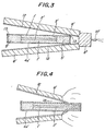
- Fig. 3 is an explanative sectional view of an apparatus used for producing an amorphous alloy shaped article in another embodiment of the method of the present invention
- Fig. 4 is an explanative sectional view, in an enlarged scale, of a part of the apparatus shown in Fig. 1, illustrating the proceeding of the explosion of an explosive in the method shown in Fig. 3.
- Figs. 1 and 2 The method illustrated in Figs. 1 and 2 is particularly advantageous for the production of a cylindrical or hollow cylindrical amorphous alloy shaped article.
- the numeral 1 represents an amorphous alloy or atomized alloy raw material powder layer
- the numeral 2 represents a metal powder layer arranged laminately and adjacently to the raw material powder layer 1
- the numeral 3 represents an amorphous alloy foil
- the numeral 4 represents a pressing vessel made of metal.
- the pressing metarvessel4 consists of, for example, a copper tube 4a and steel plugs 4b.
- An amorphous alloy foil 3 is rolled into a hollow cylinder having a diameter smaller than the inner diameter of the copper tube 4a and filled with metal powders to form a metal powder layer 2.
- the metal powder layer 2 wrapped with the amorphous alloy foil 3 is arranged in the center portion of the interior of the copper tube 4a in the form of a core, and amorphous alloy or atomized alloy raw material powders are filled in the gap between the amorphous alloy foil 3 and the copper tube 4a to form the above described amorphous alloy or atomized alloy raw material powder layer 1 around the metal powder layer 2.
- the numeral 5 represents a metal powder layer filled in spaces between the steel plugs 4b and both ends of the hollow cylindrical amorphous alloy foil 3.
- the pressing metal vessel 4 is communicated to an evacuating copper pipe 7 through an exhaust hole formed in one of the steel plugs 4b of the vessel 4 such that, when the raw material powder layer is applied with a high-energy shock pressure, the influence of the environmental atmosphere is suppressed as low as possible.
- This exhaust hole is stopped up with a graphite round rod 7 such that the powders in the vessel 4 will not go out from the vessel 4, and then the vessel 4 is embedded in the center of the steel tube 9 previously charged with an explosive 8.
- An electric blasting cap 10 is connected to the explosive 8.
- the explosive 8 is exploded by applying an electric current to the electric blasting cap 10, and the explosion pressure acts on the raw material powder layer 1 from the outer periphery of the metal vessel 4. In this case, the shock wave is propagated through the raw material powder layer 1.
- the numeral 11 represents the front of the shock wave.
- the method illustrated in Figs. 3 and 4 is adapted to produce an amorphous alloy shaped article board.
- a box-shaped metal vessel 4' In the center portion of a box-shaped metal vessel 4' are arranged an amorphous alloy or atomized alloy raw material powder layer 1', a metal powder layer 2' and again an amorphous alloy or atomized alloy raw material powder layer 1' from the bottom of the vessel in this order so as to form a laminated powder layer assembly.
- the laminated powder layer assembly is surrounded with a partition formed of an amorphous alloy foil 3', and metal powders 5' are filled in a gap formed between the amorphous alloy foil 3' partition and the periphery of the vessel 4'.
- Metal plates for example, steel plates 12, are arranged at the outerside of the vessel 4' such that the steel plates are inclined at certain given angles with respect to the upper surface and the lower surface of the vessel 4' respectively, and an explosive 8' is stuck on the surface of the outerside of each metal plate, and another explosive 8" which is the same kind as the explosive 8', is arranged so as to be contacted with the upper and lower explosives 8', and an electric blasting cap 10' is fitted to the center portion of the end surface of the explosive 8", whereby the explosive 8' is connected to the electric blasting cap 10' through the explosive 8".
- Fig. 3 illustrates diagrammatically a state wherein an evacuating copper tube shown in Fig. 1 has already been cut off.
- the numeral 13 in Fig. 3 represents a polyvinyl chloride tape for vacuum sealing.
- Fig. 4 illustrates the process, wherein the steel plates 12 collide successively and continuously with the surfaces of the vessel 4' corresponding to the proceeding of explosion.
- the reference V. represents the velocity of the proceeding of collided portion.
- the above described methods of the present invention are optimum methods for applying a high-energy shock pressure to raw material powders depending upon the shape of the shaped articles to be produced, for example, cylindrical shape, hollow cylindrical shape, or plate-like shape.
- the shape and material of the metal vessel can be freely selected depending upon the shape demanded in the resulting shaped articles.
- composition of raw material powders of amorphous alloy or atomized alloy to be used in the present invention is not particularly limited.
- Typical compositions of the amorphous alloy raw material powders are a composition consisting mainly of iron, boron and silicon or of nickel, boron and silicon, and the like; and typical compositions of atomized alloy powders are compositions of high speed steels, die steels, high tension steels and the like.
- the amorphous alloy to be used in the present invention is a three-component or four-component alloy having a composition containing a magnetic transition metal, such as iron, cobalt, nickel or the like, as a main component, and further containing silicon, boron and phosphorus as an element for ensuring the formation of amorphous texture in the alloy.
- the amorphous alloy may further contain sulfur, selenium and the like.
- atomized alloy powders obtained by a rapid cooling method can be used as raw material powders, because the atomized alloy powders are hard and difficult to be formed into a shaped article.
- the inventors have investigated theoretically and experimentally the shape and particle size of the amorphous alloy or atomized alloy raw material powders, and have found that, in order to obtain a good shaped article, it is preferable that the raw material powders consist of larger size particles (referred to as "first group particles”) and smaller size particles (referred to as “second group particles”) in a mixing ratio of the first group particles to the second group particles within the range of from 1:1 to 10:1 (in weight ratio), that the ratio of an average diameter of the first group particles to an average diameter of the second group particles lies within the range of from 2:1 to 5:1, that the ratio of maximum diameter to minimum diameter in each particle is not higher than 3:1, that the average value of the ratios of maximum diameter to minimum diameter in all the particles is not higher than 2:1.
- first group particles larger size particles
- second group particles smaller size particles in a mixing ratio of the first group particles to the second group particles within the range of from 1:1 to 10:1 (in weight ratio)
- the metal powders to be used in combination with the amorphous alloy or atomized alloy raw material powders in the present invention include powders of any metals, for example, powders of iron, nickel, titanium, copper, zirconium, hafnium, chromium, silicon and cobalt, powders of alloys of these metals, and stainless steel powders.
- the above described 2 kinds of powders are properly selected depending upon the use of the resulting shaped article.
- the 2 kinds of powders may be packed and arranged in a pressing vessel such that they are directly contacted with each other at their boundary; or they may be separated from each other by a foil or thin sheet made of an amorphous alloy or metal used as a partition, or they may be mixed with each other in a small amount at their boundary without using a partition so long as the reflection of shock wave can be substantially neglected.
- the difference in shock impedance between the amorphous alloy or atomized alloy raw material powder layer and the metal powder layer is such that the shock impedance of the metal powder layer is not more than 70% higher or lower than the shock impedance of the amorphous alloy or atomized alloy raw metal powder layer in order to suppress the reflection of harmful shock wave, which forms cracks and voids in the interior of the resulting amorphous alloy shaped article, as small as possible.
- the high-energy shock pressure to be applied to the laminated raw material powder layer assembly in the present invention is preferably at least 5 GPa and more preferably at least 8 GPa.
- the shock pressure is lower than 5 GPa, the resulting shaped article contains sometimes unsatisfactorily bonded particle portions, and the use of a shock pressure lower than 5 GPa is not preferable.
- the pressure is transmitted from the raw material powder layer to the metal powder layer and the reflection of the shock pressure is absorbed and relaxed by the metal powders during the course of pressing a laminated assembly of the raw material powder layer and metal powder layer into a compact body, and hence the resulting shaped article is substantially free from the formation of flaws, such as cracks, crevices and the like.
- substantially free from flaws means as follows.
- the working condition may be shifted from the preset condition in some portions, and the resulting shaped article may have unsatisfactory density and magnetic properties in these portions.
- the resulting shaped article may have portions, wherein very small flaws have been formed due to the same reason.
- the pressure is determined from a condition which satisfies the following formula (3):
- the values of the elements of ⁇ o ', U s ' and Up' are values of the second body and correspond to the values of ⁇ o , U s and Up of the first body, respectively.
- the above described elements in a substance having voids homogeneously dispersed therein, for example, in a mass of powders, that is, in a substance having an initial density, before a shock is applied to the substance, lower than its theoretical density can be calculated by the following formula (5) from the shock data of the substance having substantially the theoretical density in the solid state.
- Pp represents a pressure generated in a solid having a density lower than its theoretical density
- P represents a pressure generated in a solid having a theoretical density
- Y o represents a Gruneisen coefficient
- V o and V op represent specific volumes under normal temperatures and normal pressures of a solid having a theoretical density and of a solid having a density lower than its theoretical density due to the presence of voids contained therein respectively
- V represents a specific volume of both the solids when they are pressed up to the pressures of P and P P P
- the inventors have used, in the calculation of the shock pressure to be applied to an amorphous alloy, shock elements of the main component of the amorphous alloy in place of the shock elements of the amorphous alloy. That is, for example, iron has a density of 7.85 g/cm 3 under normal temperatures and normal pressures, while an amorphous alloy consisting mainly of iron (iron: 75 wt%, boron: 15 wt%, and silicon: 10 wt%) has a density of 7.38 g/cm 2 under normal temperatures and normal pressures. Therefore, when a calibration between the density of the alloy and that of iron has been previously effected, the behavior of an amorphous alloy consisting mainly of iron can be determined without troubles.
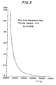
- Fig. 5 is a specific volume-pressure curve of an iron-base amorphous alloy having a packing density of 71 % based on the density of 7.38 g/cm 3 measured by the Archimedes' method.
- the pressure is calculated by the relation shown in Fig. 5 or by a specific volume-pressure relation determined in the same manner as used in the determination of the relation of Fig. 5.
- Fig. 6 is a specific volume-pressure curve of a nickel-base amorphous alloy, which is obtained by using the shock characteristics of nickel in place of the shock characteristics of the nickel-base amorphous alloy.
- the pressure relating to the nickel-base amorphous alloy was calculated based on the relation.
- the nickel-base amorphous alloy used in this calculation had a packing density of 5.72 g/cm 3 , which was 64% based on the density of 8.907 g/cm 3 of nickel.
- Figs. 7, 8 and 9 are specific volume-pressure curves of iron powders having a packing density of 70% based on the density of iron, titanium powders having a packing density of 63% based on the density of titanium, and iron powders having a packing density of 65% based on the density of iron, respectively.
- shock impedance before explained in the specification can be calculated from the above described shock wave velocity and the initial density of a substance. That is, the shock impedance S.I. is given by the following formula (8):
- the shock impedance of the above described iron-base amorphous alloy powder mass is calculated to be as follows.
- shock impedance with the shock impedance of metals, which have substantially no void, is as follows. Iron, copper and nickel have shock impedance of 3,265,000 g/ sec cm2, 3,864,000 g/sec - cm 2 and 4,410,500 g/ sec - cm 2 respectively under a pressure of 10 GPa. These shock impedances are 2.6 times, 3.1 times and 3.5 times that of the above described iron-base amorphous alloy powders, which have been packed in a packing density percentage of 71 % based on their density measured by the Archimedes' method.
- the shock wave When a shock wave is transmitted to powders having such high shock impedance after passed through amorphous alloy powders, the shock wave is necessarily reflected to cause rapid increase of pressure and to cause flaws, such as cracks and the like, in the amorphous alloy shaped article due to the above described mechanism.
- the portion when a pressure is increased in a certain portion, the portion necessarily has an internal energy higher than that in the other portion, and hence the former portion has a temperature higher than that in the latter portion, and crystallization occurs in the amorphous alloy portion near the contacting portion to the high shock impedance portion. All the amorphous alloy portions were crystallized in such portion as illustrated in Comparative Examples in this specification also.
- the packing density percentage of an amorphous alloy raw material layer or a metal powder layer is lower than a certain limit, the shock wave velocity U s and further the shock impedance S.I. can not be determined according to the above described method. Therefore, it is necessary to take care of the packing density percentages of the charged raw material powder layer and metal powder layer.
- This limit is a value defined by the following formula (9): and indicating that the powders are packed in a very low packing density.
- the shock impedance of copper powders having a packing density percentage of 21 % corresponds to about 39% of the shock impedance of the iron-base amorphous iron alloy powder mass.
- metal powders having a shock impedance within the range of 378,000 ⁇ 2,142,000 g/sec . cm 2 is preferably used.
- the shock impedance of metal having a theoretical density does not change. Therefore, the shock impedance of metal powders is adjusted by charging the powders in a vessel and controlling their packing density.
- amorphous alloy and metal having any shapes of fibrous shape, flaky shape, foamed body, calcined product of powders, and the like can be used similarly to the powdery amorphous alloy and powdery metal in so far as the alloy or metal contains voids uniformly and wholly dispersed therein.
- the shock pressure used in the production of amorphous alloy shaped articles is substantially within the range of from 5 GPa to 30 GPa, and it has been found from experiments that, when the relation between the shock impedance of the amorphous alloy powders and that of metal powders is selected such that the relation has the above described value under a pressure of 10 GPa, a good shaped article can be obtained. Accordingly, when it is intended to set the packing densities of amorphous alloy powders and metal powders, the aimed packing densities can be obtained by setting the shock impedances under 10 GPa of both the amorphous alloy powders and metal powders to necessary values.
- a good amorphous alloy shaped article can be obtained by arranging laminately amorphous alloy powders and metal powders such that they are contacted with other, and applying a shock to the laminated powder assembly from the outside to press the assembly into a compact body.
- these two kinds of powders are arranged so as to be contacted with each other at their boundary.
- a thin metal plate or an amorphous alloy foil may be arranged at the boundary of the powders as described above.
- the partition naturally has a shock impedance higher than that of metal or amorphous alloy having voids therein, and therefore there is a risk in the use of the partition that, when a shock wave is arrived at the partition, the shock wave is reflected at the partition to generate a reflected shock wave having a pressure higher than that of the original shock wave, and to cause flaws, such as cracks and the like, in the resulting shaped article.
- a metal powder layer is laminately arranged on an amorphous alloy or atomized alloy raw material powder layer, and a high-energy shock pressure is applied to the laminated powder layer assembly, whereby the generation of a harmful reflected shock wave is suppressed as low as possible. Therefore, the resulting amorphous alloy shaped article does not contain flaws nor crystallized portions therein, and the method of the present invention has such a merit that an excellent amorphous alloy shaped article substantially free from flaws can be easily obtained by a simple operation.
- the shaped article obtained by the method of the present invention can be worked into a final product and can be used in various fields. In the working, a metal layer formed together with the amorphous alloy layer is removed. Alternatively, when the formed metal layer can be contained in the final product, the amorphous alloy layer is worked together with the metal layer.
- the use of the shaped article is as follows.
- the amorphous alloy shaped article can be widely used as magnetic materials for various magnetic sensors, magnetic head, magnetic shield material, magnetic core and the like; as materials having high hardness and strength; and as a corrosion-resistant material.
- the resulting shaped article can be widely used as a material having high hardness and strength, a corrosion-resistant material, and the like.
- Nickel-base amorphous alloy raw material powders consisting of a homogeneous mixture of 50% by weight of nickel-base amorphous alloy powders having a particle size ranging from 88 pm to 44 11m and a center value of 66 11m in the particle size distribution and 50% by weight of nickel-base amorphous alloy powders having a particle size ranging from 10 pm to 3 11m and having a center value of 7 ⁇ m in the particle size distribution, were charged into the copper tube over a range of 100 ⁇ m in its center portion in its length direction so as to surround the amorphous alloy foil hollow cylindrical partition and to form a nickel-base amorphous alloy raw material powder layer having a hollow cylindrical shape surrounding the partition and having an inner diameter of 12 mm, an outer diameter of 21 mm and a length of 100 mm.
- the amorphous alloy foil hollow cylindrical partition was produced by winding a nickel-base amorphous foil having a width of 50 mm and a thickness of 35 um into a hollow cylindrical shape by overlapping the edges in a width of about 3 mm, and adhering the overlapped portion by means of a cellulose adhesive. Electrolytic iron powders having a particle size of less than 100 mesh size were filled in the inside of the hollow cylindrical partition.
- the same iron powders as described above were charged in the copper tube at the spaces ranging from both ends of the portion, wherein the amorphous alloy raw material powders and the electrolytic iron powders were charged, to its both ends, and steel plugs having a length of 20 mm and a diameter of 21.2 mm were forcedly pressed into both ends of the copper tube to seal the ends.
- a hole having a diameter of 2 mm was formed at the axial center of one of the steel plugs, and a sintered graphite round rod having an apparent density of 1.5 g/cm 3 , a length of 5 mm and a diameter of 2 mm was inserted into the hole, and an evacuating copper pipe having an outer diameter of 10 mm, an inner diameter of 8 mm and a length of 80 mm was brazed with brass to the outer surface of the steel plug at a position, wherein the evacuating copper pipe was aligned with the center axis of the copper tube containing the amorphous alloy raw material powders and electrolytic iron powders, such that the interior of the copper tube was able to be made into vacuum in the case where a shock pressure was applied to the laminately arranged amorphous alloy raw material powders and electrolytic iron powders contained in the copper tube to press the powders into a compact body.
- the boundary of the steel plug and the copper tube was brazed with brass as well for the same purpose.
- the nickel-base amorphous alloy raw material powders charged in the copper tube had a composition consisting of 75% by weight of nickel, 15% by weight of boron and 10% by weight of silicon, and had a density of 7.835 g/cm 3 measured by the Archimedes' method.
- the amount of the raw material powders charged over a 100 mm length in the center portion of the copper tube was 133.42 g, and the charged raw material powders had a packing density percentage of 73% based on their Archimedes' density.
- the packing density percentage of 73% of the raw material powders based on their Archimedes' density corresponds to a packing density percentage of 64% of the powders based on the theoretical density of nickel. Therefore, when it was intended to determine a specific volume-pressure curve of the raw material powders a specific volume-pressure curve illustrated in Fig. 6 was used in the calculation of the shock properties of the raw material powders.
- the packing density of the electrolytic iron powders was 70% based on the theoretical density of iron.
- the nickel-base amorphous alloy raw material powders charged in the above described packing density percentage of 64% based on the theoretical density of nickel had a shock impedance of 1,487,040 g/sec. cm2 under a pressure of 10 GPa
- the electrolytic iron powders charged in the packing density percentage of 70% based on the theoretical density of iron had a shock impedance of 1,280,560 gl sec - cm2 under a pressure of 10 GPa. That is, the shock impedance value of the electrolytic iron powders was 14% lower than that of the nickel-base amorphous alloy raw material powders.
- the nickel-base amorphous alloy foil arranged between the raw material powders and the electrolytic iron powders had a composition consisting of 92.3% by weight of nickel, 3.2% by weight of boron and 4.5% by weight of silicon, and had a density of 7.97 g/cm 3 .
- a thickness of 4.2 mm and a length of 300 mm was previously charged 922 g of a powdery explosive having a detonation velocity of 2,300 m/sec.
- the above described copper tube containing the nickel-base amorphous alloy raw material powders and the electrolytic iron powders and being used as a pressing tube was embedded in the explosive on the center axis of the steel tube such that one end of the copper tube was located at a position 70 cm distant from the end of the steel tube, at which end the explosive in the steel tube was exposed to air, and an electric blasting cap was fitted to the end of the steel tube at its center portion, and the explosive was detonated in an explosive sound suppressing chamber.
- the pressing copper tube containing the amorphous alloy raw material powders and electrolytic iron powders was pressed from the surroundings by the action of explosion pressure, and as the result the outer diameter of the tube was shrunk.
- the copper tube was cut and removed by means of a lathe, the amorphous alloy powders and the electrolytic iron powders had been bonded into a compact shaped article.
- the shaped article was cut off in a direction perpendicular to its center axis by means of a cutting-off wheel, and the section was observed by a naked eye, it was found that the outer layer formed of amorphous alloy layer and the inner layer formed of electrolytic iron layer were tightly bonded with each other without forming crevices and cracks.
- a cavity having an irregular but substantially tubular shape and having a diameter of 1-2.3 mm had been formed in parallel with the axis of the shaped article.
- iron powders are tightly bonded to each other, and flaws such as cracks, voids and the like, were not at all observed.
- the outer layer formed of amorphous alloy had a good formed state, wherein the boundary of particles was not substantially observed, and crystals were not at all observed. Further, the boundary of the inner layer formed of electrolytic iron layer and the outer layer formed of amorphous alloy layer and the shaped article portion formed of the electrolytic iron layer had a good formed state, and cracks and cavities were not observed with the exception of the cavity formed in the center portion of the shaped article.
- the resulting shaped article had an outer diameter of 16.8 mm.
- the outer diameter of the inner layer formed of electrolytic iron layer that is, the diameter of the boundary of the inner and outer layers was about 10 mm.
- the resulting shaped article was ground and worked into two cylinders, one of which consisted only of the amorphous alloy portion, and the other of which consisted only of the electrolyte iron portion.
- the densities of the amorphous alloy portion and the electrolytic iron portion were measured by the Archimedes' method, it was found that the density of the amorphous alloy portion was 7.819 g/cm 3 and that of the electrolytic iron portion was 7.842 g/ c m3 .
- the shock pressure generated in the amorphous alloy powders was 9.45 GPa and the shock pressures generated in the electrolytic iron powders were 9.71 GPa at the portion of the shock wave perpendicular to the proceeding direction of explosion, and 9.45 GPa at the portion of the shock wave oblique to the proceeding direction of explosion.
- the shock impedance of the amorphous allow powders was 1,447,990 g/sec - cm 2
- the shock impedances of the electrolytic iron powders were 1,262,630 g/sec. cm2 at a portion of the shock wave perpendicular to the proceeding direction of explosion and 1,247,240 g/sec . cm 2 at a portion of the shock wave oblique to the proceeding direction of explosion.
- Example 2 An experiment was carried out in the same manner as described in Example 1, except that the same amorphous alloy raw material powders as used in Example 1 alone were charged into the pressing copper tube in place of charging concentrically the amorphous alloy raw material powders and the electrolytic iron powders into the copper tube.
- the charged amount of the amorphous alloy raw material powders was 198.1 g, and the charged raw material powders had a packing density percentage of 73% based on their density measured by the Archimedes' method.
- the resulting shaped article had the same shape as the shaped article obtained in Example 1, but had the following defects. That is, when the copper tube was removed, and the shaped article was cut off, and then the section perpendicular to the center axis of the shaped article was examined, a cavity having an irregular shape and having a diameter of 2-3.5 mm was observed in the center portion of the shaped article, and radial cracks extended irregularly in the shaped article from the cavity.
- the cracked portion of the shaped article was ground and removed from the shaped article to obtain that portion of the shaped article which did not contain cracks nor voids and was judged to be satisfactorily formed.
- the resulting shaped article containing no cracks and the like had a density of 7.792 g/cm 3 measured by the Archimedes' method. This value corresponds to 99.5% of the theoretical density of the amorphous alloy, and was 0.3% lower than the percentage of 99.8% of the Archimedes' density of the amorphous alloy portion of the shaped article obtained in Example 1 to the theoretical density of the amorphous alloy.
- the shaped article having no cracks and the like and being judged to be good had a weight of 33.8 g, and the yield of the shaped article based on the amount of raw material powders was as low as only 17.1 %. While, in Example 1, when the weight of the amorphous alloy portion of the shaped article was deduced from the outer shape of the whole body of the shaped article finally obtained and judged to be free from flaws, and the yield of the amorphous alloy portion was calculated, the yield was calculated to be not less than 88%. Therefore, the yield of 17.1% in this Comparative Example 1 is very low as compared with the yield of not less than 88% in Example 1.
- the shaped article in Example 1 is very small in the size of cracks and voids and has a very excellent bonded state as compared with the shaped article in Comparative Example 1.
- the amorphous alloy portion of the shaped article of Example 1 had an X-ray diffraction pattern consisting only of halopatterns, but the amorphous alloy shaped article of Comparative Example 1 had peaks indicating the presence of crystal.
- the former had only a random structure of atoms, but the latter had a regular arrangement of atoms. It can be judged from the results that, even after the formation, the former still has an amorphous state, while in the latter, crystallization occurs.
- Amorphous alloy raw material powders which had the same composition as that of the amorphous alloy foil used in Example 1 and had a particle size smaller than 140 mesh size, were charged in the box at the center portion of the bottom in a depth of 5 mm, a width of 30 mm and a length of 80 mm.
- a partition produced from the same amorphous alloy foil as used in Example 1 was previously arranged uprightly in the steel box such that the amorphous alloy raw material powders could be arranged in a proper shape.
- flaky titanium powders having a particle size smaller than 100 mesh size were arranged in a thickness of 5 mm. Further, on the titanium powders, the same amorphous alloy powders as those charged in the bottom of the box were charged in a thickness of 5 mm, whereby the upper surface of the charged powders was agreed with the upper edge of the box. That is, in a steel box having no upper cover, a partition was produced from an amorphous alloy foil, and further a three-layered sandwich-like powder layer consisting of amorphous alloy powders-titanium powders-amorphous alloy powders was formed inside the partition.
- titanium powders were filled in a space formed outside the partition, that is, in a space between the inner wall of the steel box and the amorphous alloy foil partition, which surrounds the three-layered powder layer, and a cover made of steel and having a thickness of 1.6 mm, a width of 53 mm and a length of 153 mm, was arranged on the box, and the edge portion of the box was sealed by an adhesive tape made of polyvinyl chloride, and further gaps formed in the edge portion were sealed by a vacuum grease, whereby the interior of the box was kept airtight.
- An evacuating copper pipe was brazed to the steel box such that the interior of the box was able to be made into vacuum in the case where an explosion pressure was applied to the three layered powder layer to press the powder layer into a compact body.
- the charged amorphous alloy powders had a packing density of 77.5% based on their theoretical density, and the charged titanium powders had a packing density of 63% based on the density of 4.51 g/cm 3 of titanium having no voids.
- the amorphous alloy powders had a shock impedance of 1,392,170 g/sec. cm2 and the titanium powders had a shock impedance of 836,714 g/sec. cm2, under a pressure of 10 GPa. That is, the shock impedance of the titanium powders is about 40% lower than that of the amorphous alloy powders.
- the interior of the box was deaerated by means of a rotary vacuum pump to keep the vacuum degree in the interior of the box to 10- 2 Torr, and the evacuating copper pipe was sealed, and then an explosion shock was applied to the box.
- Both the amorphous alloy raw material powders and the titanium powders had previously been subjected to a treatment for removing gases adsorbed to the powders before the powders were charged into the box.
- Fig. 3 illustrates a method for applying an explosion shock to the box.
- steel sheets having a thickness of 1.6 mm, a width of 130 mm and a length of 200 mm were arranged on the upper side and lower side of the shorter edges of the steel box such that one surface of each steel sheet was faced to the upper or lower surface of the steel box and was inclined at an angle of 10° with respect to the upper or lower surface of the box, and an explosive having a detonation velocity of 4,200 m/sec was stuck to another surface of the steel sheets in a thickness of 15 mm, which surface was not faced to the upper or lower surface of the box, over the whole area of the steel sheets, and further another explosive, which was the same kind as the above described explosive and had a cross-sectional shape of 30 cm square and a length of 130 mm, was arranged such that the explosive would contact with the above described two explosives.
- An electric blasting cap was fitted to the center portion of the latter explosive, and the explosive was detonated, whereby the total explosive
- Fig. 4 illustrates the process of collision of the steel sheets with the surfaces of the box.
- the reference V c represents the proceeding velocity of colliding portion.
- the velocity V. was 2,640 m/sec.
- the steel box containing the amorphous alloy powders and titanium powders was completely broken and flown away by the explosion shock applied thereto, except that a part of the steel sheets were bonded to the resulting shaped article.
- the shaped article was recovered in a state substantially free from damage, except that cracks were observed in the peripheral portion of the titanium layer, which were extending in parallel to the edge of the outer periphery of the titanium layer at a position 5-8 mm distant from the edge, and further a part of the edge was broken in the form of 3-5 mm square.
- Example 2 An experiment was carried out in the same manner as described in Example 2, except that an amorphous alloy powder layer was arranged between titanium powder layers contrary to Example 2, wherein a titanium powder layer was arranged between amorphous alloy powder layers.
- Example 2 An experiment was carried out in the same manner as described in Example 2, except that atomized SKH 9 steel powders produced by a rapid cooling method were used in place of the amorphous alloy powders used in Example 2 and a thin titanium plate having a thickness of 0.3 mm was used as a partition in place of the amorphous alloy foil used in Example 2.
- the atomized SKH 9 steel powders there was used a mixture of atomized SKH 9 steel powders having an average particle size of about 120 11m and having a particle size distribution ranging from 30 pm to 250 11m and atomized SKH 9 steel powders having an average particle size of about 15 ⁇ m and having a particle size distribution ranging from 6 ⁇ m to 30 ⁇ m in a mixing ratio (in weight ratio) of 2:1.
- the mixed atomized powders had a density of 7.95 g/cm 3 measured by the Archimedes' method, and had a density of 5.10 g/cm 3 in the charged state in the steel box. Accordingly, the density of the atomized powders in the charged state corresponds to 65% of the theoretical density of the steel.
- the shock impedance of the amorphous alloy powders a specific volume-pressure curve of iron having a packing density percentage of 65% (shown in Fig. 9) was used.
- the atomized powders have a shock impedance of 1,161,030 g/sec . cm 2 under a pressure of 10 GPa
- titanium powders having a packing density percentage of 63% have a shock impedance of 836,714 g/sec. cm2 under a pressure of 10 GPa, that is, the shock impedance of the titanium powders is about 28% lower than that of the atomized powders.
- a shaped article was produced by applying a shock to the laminated powder layer assembly in the same manner as described in Example 2, and the resulting shaped article was cut off in a direction perpendicular to the major axis of the shaped article, and the section was observed by a naked eye and a microscope with respect to the SKH 9 steel outer layer and to the titanium inner layer of the shaped article. It was found that the SKH 9 steel layer was tightly bonded to the titanium layer, and neither cracks nor voids were observed in both layers. The SKH 9 steel portion and titanium portion were separately cut out, and the density of each portion was measured by the Archimedes' method. It was found that the SKH 9 steel portion had a density of 99.4% based on the theoretical density of the SKH 9 steel, and the titanium portion had a density of 99.7% based on the theoretical density of titanium.
- Example 3 An experiment was carried out in the same manner as described in Example 3, except that the atomized SKH 9 steel powders and titanium powders were arranged in the reverse order to the order in Example 3.
- Example 2 An experiment was carried out in the same manner as described in Example 1, except that electrolytic copper powders were used in place of the electrolytic iron powders used in Example 1.
- the packing density of the electrolytic copper powders was 1,869 g/cm 3 , which was 21 % based on the theoretical density of copper.
- the shock impedance value of the charged amorphous alloy powders, and that of the charged electrolytic copper powders, and the ratio in percentage of the shock impedance value of the amorphous alloy powders to that of the copper powders are the values already explained in this specification.
- an amorphous alloy foil was not used in the boundary between the amorphous alloy powder layer and the electrolytic copper powder layer, but the electrolytic copper powders were embedded in the amorphous alloy powders in the following manner. That is, the electrolytic copper powders were agglomerated into a round rod by the use of about 10% by weight, based on the amount of the copper powders, of polyvinyl alcohol as a binder, and the round rod consisting of the copper powders agglomerated together with the polyvinyl alcohol was arranged in the center portion of the same steel tube as described in Example 1, the same amorphous alloy raw material powders as used in Example 1 were charged in the steel tube so as to surround the round rod and the assembly was subjected to a deaeration treatment to decompose and remove the polyvinyl alcohol, whereby the electrolytic copper powder layer was formed inside the annular amorphous alloy raw material powder layer without arranging the amorphous alloy foil between both the powder layers.
- the shaped article obtained by applying a shock pressure to the laminated powder layer assembly was a good shaped article free from cracks, void and crystallized portions in the amorphous alloy layer similarly to the shaped article obtained in Example 1, except that the diameter of metal portion is smaller than that of the metal portion in the shaped article of Example 1, due to the reason that the packing density percentage of the metal powders in this Example 4 was lower than that of the metal powders in
- Example 4 An experiment was carried out in the same manner as described in Example 4, except that the round rod consisting of agglomerated electrolytic copper powders and used in Example 4 was replaced by a copper round rod having the same dimension as that of the rod used in Example 4,
- the round copper rod used in this experiment had the theoretical density of copper, and the shock impedance of the round copper rod was 3,864,000 g/sec - cm 2 , which was 3.1 times of 1,260,000 g/sec - cm 2 of the shock impedance of the amorphous alloy powders, that is, the shock impedance of the round copper rod was 210% higher than that of the amorphous alloy powders.
Landscapes
- Engineering & Computer Science (AREA)
- Manufacturing & Machinery (AREA)
- Mechanical Engineering (AREA)
- Chemical & Material Sciences (AREA)
- Crystallography & Structural Chemistry (AREA)
- Powder Metallurgy (AREA)
Claims (12)
Applications Claiming Priority (4)
| Application Number | Priority Date | Filing Date | Title |
|---|---|---|---|
| JP260844/84 | 1984-12-12 | ||
| JP59260844A JPS61139629A (ja) | 1984-12-12 | 1984-12-12 | アモルフアス金属焼結体の製造法 |
| JP60162899A JPH0733523B2 (ja) | 1985-07-25 | 1985-07-25 | 非晶金属質成形体ないしは結晶金属質成形体の製造方法 |
| JP162899/85 | 1985-07-25 |
Publications (3)
| Publication Number | Publication Date |
|---|---|
| EP0187476A2 EP0187476A2 (de) | 1986-07-16 |
| EP0187476A3 EP0187476A3 (en) | 1986-07-30 |
| EP0187476B1 true EP0187476B1 (de) | 1990-11-14 |
Family
ID=26488526
Family Applications (1)
| Application Number | Title | Priority Date | Filing Date |
|---|---|---|---|
| EP85308857A Expired - Lifetime EP0187476B1 (de) | 1984-12-12 | 1985-12-05 | Herstellung von Formteilen aus amorphen Legierungen |
Country Status (3)
| Country | Link |
|---|---|
| US (1) | US4713871A (de) |
| EP (1) | EP0187476B1 (de) |
| DE (1) | DE3580577D1 (de) |
Cited By (5)
| Publication number | Priority date | Publication date | Assignee | Title |
|---|---|---|---|---|
| RU2240205C1 (ru) * | 2003-06-09 | 2004-11-20 | Волгоградский государственный технический университет (ВолгГТУ) | Способ получения композиционных сверхпроводящих изделий из порошка |
| RU2318632C2 (ru) * | 2006-03-31 | 2008-03-10 | Государственное образовательное учреждение высшего профессионального образования Волгоградский государственный технический университет (ВолгГТУ) | Способ получения изделий из порошков |
| RU2341354C2 (ru) * | 2006-12-20 | 2008-12-20 | Государственное образовательное учреждение высшего профессионального образования Волгоградский государственный технический университет (ВолгГТУ) | Способ получения композиционных титанографитовых изделий с внутренней полостью из порошков |
| RU2349419C2 (ru) * | 2007-04-17 | 2009-03-20 | Государственное образовательное учреждение высшего профессионального образования Волгоградский государственный технический университет (ВолгГТУ) | Способ получения композиционных сверхпроводящих изделий |
| RU2349420C2 (ru) * | 2007-04-17 | 2009-03-20 | Государственное образовательное учреждение высшего профессионального образования Волгоградский государственный технический университет (ВолгГТУ) | Способ получения изделий из керамического порошка |
Families Citing this family (10)
| Publication number | Priority date | Publication date | Assignee | Title |
|---|---|---|---|---|
| US4717627A (en) * | 1986-12-04 | 1988-01-05 | The United States Of America As Represented By The United States Department Of Energy | Dynamic high pressure process for fabricating superconducting and permanent magnetic materials |
| EP0271095A3 (de) * | 1986-12-12 | 1989-07-12 | Nippon Steel Corporation | Verfahren zur Herstellung von Formkörpern aus Pulvern, Folien oder feinen Drähten |
| DE3821304A1 (de) * | 1988-06-24 | 1989-12-28 | Kernforschungsanlage Juelich | Explosionskammer zur werkstoffbearbeitung durch explosionsverfahren |
| US4881314A (en) * | 1988-09-23 | 1989-11-21 | Rolls Royce, Inc. | Method of explosively forming a multilayered composite material |
| EP0985701B1 (de) | 1998-09-11 | 2007-07-11 | Toray Industries, Inc. | Mehrschichtige, biaxial orientierte Polyesterfolie und Verfahren zu ihrer Herstellung |
| FR2832335B1 (fr) * | 2001-11-19 | 2004-05-14 | Bernard Pierre Serole | Procede de compactage et soudure de materiaux par ajustement de la vitesse d'une onde de choc au cours de la traversee de materiaux |
| US20050084407A1 (en) * | 2003-08-07 | 2005-04-21 | Myrick James J. | Titanium group powder metallurgy |
| NO20034035D0 (no) * | 2003-09-11 | 2003-09-11 | Opera Software Asa | Skjelne og fremvise tabeller i dokumenter |
| CN106825558B (zh) * | 2017-04-07 | 2018-10-02 | 华北理工大学 | 一种活性复合材料爆炸成型模具 |
| CN111195506B (zh) * | 2020-01-21 | 2021-01-15 | 成都奇点无限科技有限公司 | 一种爆轰式合成装置 |
Family Cites Families (6)
| Publication number | Priority date | Publication date | Assignee | Title |
|---|---|---|---|---|
| US3112166A (en) * | 1960-03-10 | 1963-11-26 | Ici Ltd | Formation of hollow bodies from powdered materials |
| US3084398A (en) * | 1961-01-18 | 1963-04-09 | Du Pont | Compaction process |
| US3568248A (en) * | 1969-03-04 | 1971-03-09 | Du Pont | Plug closure in a container for subjecting sample to shock wave |
| SE430479B (sv) * | 1980-11-10 | 1983-11-21 | Cerac Inst Sa | Form for kompaktering av pulver medelst en stotvag |
| SE451549B (sv) * | 1983-05-09 | 1987-10-19 | Kloster Speedsteel Ab | Pulvermetallurgisk metod att framstella metallkroppar av magnetiserbart sferiskt pulver |
| US4490329A (en) * | 1983-09-08 | 1984-12-25 | Oregon Graduate Center For Study And Research | Implosive consolidation of a particle mass including amorphous material |
-
1985
- 1985-12-02 US US06/803,238 patent/US4713871A/en not_active Expired - Fee Related
- 1985-12-05 EP EP85308857A patent/EP0187476B1/de not_active Expired - Lifetime
- 1985-12-05 DE DE8585308857T patent/DE3580577D1/de not_active Expired - Lifetime
Cited By (5)
| Publication number | Priority date | Publication date | Assignee | Title |
|---|---|---|---|---|
| RU2240205C1 (ru) * | 2003-06-09 | 2004-11-20 | Волгоградский государственный технический университет (ВолгГТУ) | Способ получения композиционных сверхпроводящих изделий из порошка |
| RU2318632C2 (ru) * | 2006-03-31 | 2008-03-10 | Государственное образовательное учреждение высшего профессионального образования Волгоградский государственный технический университет (ВолгГТУ) | Способ получения изделий из порошков |
| RU2341354C2 (ru) * | 2006-12-20 | 2008-12-20 | Государственное образовательное учреждение высшего профессионального образования Волгоградский государственный технический университет (ВолгГТУ) | Способ получения композиционных титанографитовых изделий с внутренней полостью из порошков |
| RU2349419C2 (ru) * | 2007-04-17 | 2009-03-20 | Государственное образовательное учреждение высшего профессионального образования Волгоградский государственный технический университет (ВолгГТУ) | Способ получения композиционных сверхпроводящих изделий |
| RU2349420C2 (ru) * | 2007-04-17 | 2009-03-20 | Государственное образовательное учреждение высшего профессионального образования Волгоградский государственный технический университет (ВолгГТУ) | Способ получения изделий из керамического порошка |
Also Published As
| Publication number | Publication date |
|---|---|
| EP0187476A2 (de) | 1986-07-16 |
| US4713871A (en) | 1987-12-22 |
| DE3580577D1 (de) | 1990-12-20 |
| EP0187476A3 (en) | 1986-07-30 |
Similar Documents
| Publication | Publication Date | Title |
|---|---|---|
| EP0187476B1 (de) | Herstellung von Formteilen aus amorphen Legierungen | |
| US4711795A (en) | Method of manufacturing an amorphous-metal-coated structure | |
| US3401019A (en) | Process for synthesizing diamond | |
| Morris | Compaction and mechanical properties of metallic glass | |
| US3667911A (en) | Method of treating solids with high dynamic pressure | |
| EP0155066A1 (de) | Gesinterter Diamantkörper | |
| Clyens et al. | The dynamic compaction of powdered materials | |
| US3220103A (en) | Method of explosively compacting powders to form a dense body | |
| US4282034A (en) | Amorphous metal structures and method | |
| Prümmer | Explosive compaction of powders, principle and prospects | |
| GB2198678A (en) | Dynamic high pressure process for fabricating superconducting and permanent magnetic materials | |
| JP2533529B2 (ja) | アモルフアス金属−金属複合体及びその製造方法 | |
| EP0022433A1 (de) | Verfahren zur Herstellung von Objekten mit einer Dicke von mehr als 100 micrometer aus schnell abgeschreckten metastabilen Pulvern | |
| US3641298A (en) | Electrically conductive material and electrical contact | |
| Peng et al. | Explosive consolidation of rapidly solidified aluminum alloy powders | |
| Zhang et al. | Preparation of bulk nano-aluminum materials from nanopowder using explosive consolidation | |
| Andilevko et al. | Specific features of mass transfer of discrete microparticles in the process of metallic target treatment with a powder flux | |
| JPH0733523B2 (ja) | 非晶金属質成形体ないしは結晶金属質成形体の製造方法 | |
| JPH0610282B2 (ja) | アモルフアス金属成形体の製造方法 | |
| Andrews et al. | Temperature dependence of the impact response of copper: erosion by melting | |
| US3851027A (en) | Shock-bonding of hard particles | |
| JP2951349B2 (ja) | 水中衝撃波を利用した粉末圧搾体の製造方法 | |
| JP2669308B2 (ja) | アモルファス被覆体及びその成形方法 | |
| US4757219A (en) | Lamination type of magnetostrictor and manufacturing method thereof | |
| Mamalis et al. | A consolidation mechanism for the compaction of copper powder at high pressures |
Legal Events
| Date | Code | Title | Description |
|---|---|---|---|
| PUAI | Public reference made under article 153(3) epc to a published international application that has entered the european phase |
Free format text: ORIGINAL CODE: 0009012 |
|
| PUAL | Search report despatched |
Free format text: ORIGINAL CODE: 0009013 |
|
| AK | Designated contracting states |
Kind code of ref document: A2 Designated state(s): DE FR SE |
|
| AK | Designated contracting states |
Kind code of ref document: A3 Designated state(s): DE FR SE |
|
| 17P | Request for examination filed |
Effective date: 19861117 |
|
| 17Q | First examination report despatched |
Effective date: 19880330 |
|
| GRAA | (expected) grant |
Free format text: ORIGINAL CODE: 0009210 |
|
| AK | Designated contracting states |
Kind code of ref document: B1 Designated state(s): DE FR SE |
|
| REF | Corresponds to: |
Ref document number: 3580577 Country of ref document: DE Date of ref document: 19901220 |
|
| ET | Fr: translation filed | ||
| PLBE | No opposition filed within time limit |
Free format text: ORIGINAL CODE: 0009261 |
|
| STAA | Information on the status of an ep patent application or granted ep patent |
Free format text: STATUS: NO OPPOSITION FILED WITHIN TIME LIMIT |
|
| 26N | No opposition filed | ||
| EAL | Se: european patent in force in sweden |
Ref document number: 85308857.3 |
|
| PGFP | Annual fee paid to national office [announced via postgrant information from national office to epo] |
Ref country code: FR Payment date: 19951212 Year of fee payment: 11 |
|
| PGFP | Annual fee paid to national office [announced via postgrant information from national office to epo] |
Ref country code: DE Payment date: 19951214 Year of fee payment: 11 |
|
| PGFP | Annual fee paid to national office [announced via postgrant information from national office to epo] |
Ref country code: SE Payment date: 19951215 Year of fee payment: 11 |
|
| PG25 | Lapsed in a contracting state [announced via postgrant information from national office to epo] |
Ref country code: SE Effective date: 19961206 |
|
| PG25 | Lapsed in a contracting state [announced via postgrant information from national office to epo] |
Ref country code: FR Effective date: 19970829 |
|
| PG25 | Lapsed in a contracting state [announced via postgrant information from national office to epo] |
Ref country code: DE Effective date: 19970902 |
|
| EUG | Se: european patent has lapsed |
Ref document number: 85308857.3 |
|
| REG | Reference to a national code |
Ref country code: FR Ref legal event code: ST |