EP0187397B1 - Pulse radar apparatus - Google Patents
Pulse radar apparatus Download PDFInfo
- Publication number
- EP0187397B1 EP0187397B1 EP85201846A EP85201846A EP0187397B1 EP 0187397 B1 EP0187397 B1 EP 0187397B1 EP 85201846 A EP85201846 A EP 85201846A EP 85201846 A EP85201846 A EP 85201846A EP 0187397 B1 EP0187397 B1 EP 0187397B1
- Authority
- EP
- European Patent Office
- Prior art keywords
- target
- spectrum
- dft
- pulse
- cluster
- Prior art date
- Legal status (The legal status is an assumption and is not a legal conclusion. Google has not performed a legal analysis and makes no representation as to the accuracy of the status listed.)
- Expired
Links
- 238000001228 spectrum Methods 0.000 claims description 159
- 238000002592 echocardiography Methods 0.000 claims description 33
- 238000001514 detection method Methods 0.000 claims description 9
- 238000005070 sampling Methods 0.000 claims description 3
- 238000005259 measurement Methods 0.000 claims 1
- 230000000306 recurrent effect Effects 0.000 claims 1
- 239000013598 vector Substances 0.000 description 60
- 230000001427 coherent effect Effects 0.000 description 6
- 238000010586 diagram Methods 0.000 description 4
- 230000003247 decreasing effect Effects 0.000 description 2
- 230000000694 effects Effects 0.000 description 2
- 230000010363 phase shift Effects 0.000 description 2
- 238000006243 chemical reaction Methods 0.000 description 1
- 230000007423 decrease Effects 0.000 description 1
- 238000000034 method Methods 0.000 description 1
- 239000004576 sand Substances 0.000 description 1
- 230000001629 suppression Effects 0.000 description 1
Images

Classifications
-
- G—PHYSICS
- G01—MEASURING; TESTING
- G01S—RADIO DIRECTION-FINDING; RADIO NAVIGATION; DETERMINING DISTANCE OR VELOCITY BY USE OF RADIO WAVES; LOCATING OR PRESENCE-DETECTING BY USE OF THE REFLECTION OR RERADIATION OF RADIO WAVES; ANALOGOUS ARRANGEMENTS USING OTHER WAVES
- G01S13/00—Systems using the reflection or reradiation of radio waves, e.g. radar systems; Analogous systems using reflection or reradiation of waves whose nature or wavelength is irrelevant or unspecified
- G01S13/02—Systems using reflection of radio waves, e.g. primary radar systems; Analogous systems
- G01S13/06—Systems determining position data of a target
- G01S13/08—Systems for measuring distance only
- G01S13/10—Systems for measuring distance only using transmission of interrupted, pulse modulated waves
- G01S13/22—Systems for measuring distance only using transmission of interrupted, pulse modulated waves using irregular pulse repetition frequency
-
- G—PHYSICS
- G01—MEASURING; TESTING
- G01S—RADIO DIRECTION-FINDING; RADIO NAVIGATION; DETERMINING DISTANCE OR VELOCITY BY USE OF RADIO WAVES; LOCATING OR PRESENCE-DETECTING BY USE OF THE REFLECTION OR RERADIATION OF RADIO WAVES; ANALOGOUS ARRANGEMENTS USING OTHER WAVES
- G01S13/00—Systems using the reflection or reradiation of radio waves, e.g. radar systems; Analogous systems using reflection or reradiation of waves whose nature or wavelength is irrelevant or unspecified
- G01S13/02—Systems using reflection of radio waves, e.g. primary radar systems; Analogous systems
- G01S13/06—Systems determining position data of a target
- G01S13/08—Systems for measuring distance only
- G01S13/10—Systems for measuring distance only using transmission of interrupted, pulse modulated waves
- G01S13/20—Systems for measuring distance only using transmission of interrupted, pulse modulated waves whereby multiple time-around echoes are used or eliminated
-
- G—PHYSICS
- G01—MEASURING; TESTING
- G01S—RADIO DIRECTION-FINDING; RADIO NAVIGATION; DETERMINING DISTANCE OR VELOCITY BY USE OF RADIO WAVES; LOCATING OR PRESENCE-DETECTING BY USE OF THE REFLECTION OR RERADIATION OF RADIO WAVES; ANALOGOUS ARRANGEMENTS USING OTHER WAVES
- G01S13/00—Systems using the reflection or reradiation of radio waves, e.g. radar systems; Analogous systems using reflection or reradiation of waves whose nature or wavelength is irrelevant or unspecified
- G01S13/02—Systems using reflection of radio waves, e.g. primary radar systems; Analogous systems
- G01S13/50—Systems of measurement based on relative movement of target
- G01S13/52—Discriminating between fixed and moving objects or between objects moving at different speeds
- G01S13/522—Discriminating between fixed and moving objects or between objects moving at different speeds using transmissions of interrupted pulse modulated waves
- G01S13/524—Discriminating between fixed and moving objects or between objects moving at different speeds using transmissions of interrupted pulse modulated waves based upon the phase or frequency shift resulting from movement of objects, with reference to the transmitted signals, e.g. coherent MTi
- G01S13/53—Discriminating between fixed and moving objects or between objects moving at different speeds using transmissions of interrupted pulse modulated waves based upon the phase or frequency shift resulting from movement of objects, with reference to the transmitted signals, e.g. coherent MTi performing filtering on a single spectral line and associated with one or more range gates with a phase detector or a frequency mixer to extract the Doppler information, e.g. pulse Doppler radar
- G01S13/532—Discriminating between fixed and moving objects or between objects moving at different speeds using transmissions of interrupted pulse modulated waves based upon the phase or frequency shift resulting from movement of objects, with reference to the transmitted signals, e.g. coherent MTi performing filtering on a single spectral line and associated with one or more range gates with a phase detector or a frequency mixer to extract the Doppler information, e.g. pulse Doppler radar using a bank of range gates or a memory matrix
-
- G—PHYSICS
- G01—MEASURING; TESTING
- G01S—RADIO DIRECTION-FINDING; RADIO NAVIGATION; DETERMINING DISTANCE OR VELOCITY BY USE OF RADIO WAVES; LOCATING OR PRESENCE-DETECTING BY USE OF THE REFLECTION OR RERADIATION OF RADIO WAVES; ANALOGOUS ARRANGEMENTS USING OTHER WAVES
- G01S7/00—Details of systems according to groups G01S13/00, G01S15/00, G01S17/00
- G01S7/02—Details of systems according to groups G01S13/00, G01S15/00, G01S17/00 of systems according to group G01S13/00
- G01S7/28—Details of pulse systems
- G01S7/285—Receivers
- G01S7/292—Extracting wanted echo-signals
- G01S7/2923—Extracting wanted echo-signals based on data belonging to a number of consecutive radar periods
Definitions
- the invention relates to a pulse radar apparatus .
- a pulse radar apparatus provided with a transmitting and receiving unit, whereby the received target echoes are sampled and digitised after detection; an n-point DFT processing unit; a threshold circuit; and a cluster combiner circuit comprising means for combining radar cells, collectively covering one single target, to form a cluster from the signals obtained from the threshold circuit, for determining a signal representing the target covered by the cluster and hence the target range and azimuth.
- Such a pulse radar apparatus is known from the European Patent Specification EP-A- 0.057.949, describing the presence of a cell classification unit between the threshold circuit and the cluster combiner circuit.
- This unit permits to make a preliminary distinction between first- and multiple-time-around echoes in the cells on account of the spectrum range, as here the first-time-around echoes, but not the multiple-time-around echoes are coherently detected.
- a final distinction between first- and multiple-time-around echoes is made in the cluster.
- This system is unsuitable in case of coherent or non-coherent detection of both the first- and the multiple-time-around echoes, the reason being that in such a case the spectrum range no longer shows any difference.
- a target-representing signal is derived from a first- or a multiple-time-around echo
- reference is hereinafter made to a first- or a multiple-time- around target.
- the present invention has for its object to provide, irrespective of the fact of coherent or non- coherent detection of the first- or multiple-time-around echoes, means for determining whether the target-representing signal is derived from a first-or a multiple-time-around echo.
- the invention relates to a pulse radar apparatus according to Claim 1.
- the pulse radar apparatus in a simple way in order that, if the classification unit has not defined a target as being a multiple-time-around target, this unit establishes the value of P from the ratio between the local maximum values, where 2P is equal to the quotient of the doppler frequency and the pulse repetition frequency.
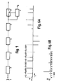
- the radar antenna 1 is connected to a transmitting and receiving unit 2.
- the transmitting unit 2 is provided with a TWT, permitting coherent detection of both first- and second-time-around echoes.
- the receiving unit 2 produces echo signals having been sampled and digitised.
- the digitised signals are subsequently Fourier-transformed in an n-point DFT processor 3, that is,video data supplied from n successive radar scans and situated in one range bin is converted into n output signals in the n frequency output signals of the DFT processor.
- a conversion will hereinafter be designated by a DFT sweep. If the video data from radar sweeps 1, 2, 3, ..., n for all eligible range bins is converted into frequency data, the video data from radar sweeps n-k'+1, n-k'+2, ..., 2n-k' for each of the eligible range bins is then converted into frequency data.
- k' may assume the values 0, 1, 2, ..., n-1.
- the successive DFT sweeps thus correspond with adjoining or more or less overlapping azimuth sectors.
- the signals produced by the DFT processor 3 are supplied to threshold circuit 4 eliminating clutter and noise.
- the output signals of threshold circuit 4 are supplied to a cluster combiner circuit 5, comprising means for combining radar cells, collectively covering one single target, to form a cluster, using the signals obtained from the threshold circuit, for determining a signal representing the target covered by the cluster.
- cluster combiner circuit is described in the cited European Patent Specification. From the signal obtained the cluster combiner circuit 5 also determines the target range and azimuth.
- Cluster combiner circuit 5 is capable of covering a multiplicity of targets.
- This wobble enables to establish, on account of the target range and azimuth information from cluster combiner circuit 5, whether an echo is a first- or a second-time-around echo; in case of a second-time-around echo, the target range information from cluster combiner circuit 5 will assume two values with a mutual difference corresponding with the wobble time, whereas a first-time-around echo will yield the same or substantially the same range value with each detection.
- the azimuth value from cluster combiner circuit 5 will practically remain unchanged.
- the application of a wobble has the disadvantage that the DFT spectrum changes due to the wobble: the main spectrum of the received target echoes containing the doppler information is accompanied with a secondary spectrum whose local maximum value is at a distance of kn times the bandwidth of the DFT processor output channels away from that of the main spectrum.
- the main spectrum of the received target echoes containing the doppler information is accompanied with a secondary spectrum whose local maximum value is at a distance of kn times the bandwidth of the DFT processor output channels away from that of the main spectrum.
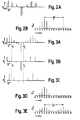
- Fig. 2A showing an echo pulse train containing a wobble
- Fig. 2B showing the DFT spectrum of Fig. 2A.
- the absolute value F of the generally complex DFT spectrum is depicted in Figs. 2B, 3D 3E, 6B and 7E. It is further assumed that a 16-point DFT is applied, where the 16 output channels U are consecutively numbered from 0 to 15.
- first- and second-time-around echoes see that on account of the target range and azimuth information from combiner circuit 5 it is possible that two different targets are defined as being one second-time-around target if these targets, viewed from the radar antenna, are behind each other at a range corresponding with the wobble period.
- a second-time-around echo the magnitude of the secondary spectrum in the DFT spectrum is equal to that of the main spectrum, see Fig.
- a secondary spectrum in case of first-time-around echoes due to a wobble may be explained as follows.
- a train of n echo pulses P at an interval T will give a spectrum as shown in Fig. 3D.
- the echo pulse train of Fig. 3A may be conceived to be the sum of two echo pulse trains S and Q, as illustrated in Figs. 3B and 3C.
- the absolute value of the DFT spectrum of echo pulse train S is indicated in Fig. 3E.
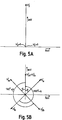
- Two equivalent spectra are formed, each being a distant of %n output channels apart. This is explained with the aid of Fig.
- the first three signal vectors of echo pulse train S in Fig. 3B are set out in the complex plane.
- the second signal vector is here the zero vector.
- IV 2 al; see Fig. 4B.
- Fig. 4B From Fig. 4B it is seen that the angular difference between successive a-vectors is a ° and that the angular difference between successive b-vectors is 1800+a.
- the angular difference of successive a- and b-vectors is thus 180 ° , corresponding with a distance of .n filter channels between the main and the secondary spectra in the complex DFT spectrum, as the a-vectors determine the main spectrum and the b-vectors the secondary spectrum.
- the spectrum of the echo pulse train Q can be regarded in the same way. Echo pulse train Q corresponds with echo pulse train S shifted over a period T. This means that there is a phase difference between the complex DFT spectrum of echo pulse trains S and Q.
- Fig. 5A the first three signal vectors of echo pulse train Q are set out.
- the first and the third signal vectors here designated V1 and V' 3 , are equal to the zero vector.
- V' 3a l
- a second-time-around echo the echoes are omitted alternately, since 50% of the echoes are detected at a range R 1 and 50% at a range R 2 , where the difference in range,
- the echo pulse train type of a second-time-around echo thus corresponds with one of the pulse trains S or Q of Fig. 3.
- the associated spectrum of a second-time-around echo therefore corresponds with the spectrum of Fig. 3E; here the main and secondary spectra are equal, unlike the spectrum of a first-time-around echo. This explains the spectra of first- and second-time-around echoes, whereby a wobble may or may not be applied to the pulse repetition period.
- the cluster combiner circuit 5 of the pulse radar apparatus comprises means for determining the magnitude of local maximum values and the associated output channel number from the DFT spectrum defined by the target-representing signal. From the range, azimuth, local maximum values, and the associated output channel number of the target or targets, as determined by cluster combiner circuit 5, the classification unit 6 decides whether a target is a second-time-around target.
- target is a second-time-around target
- the pulse radar apparatus described above can simply be extended for the suppression of third-time-around echoes, in addition to second-time-around echoes.
- T T 1
- This cycle is subsequently repeated.
- this will be designated by a pulse repetition period containing two wobbles, where the wobble times are equal to AT and 2AT.
- the pulse radar apparatus described below has a pulse repetition period containing two wobbles.
- Transmitting unit 2 is now provided with means for applying two wobbles to the pulse repetition period.
- the "wobbles" enable to determine whether an echo is, on the one hand, a first-time-around echo or, on the other hand, a second- or a third-time-around echo; the second- or third-time-around echoes will hereinafter be designated second/third-time-around echoes.
- the target range determined by combiner circuit 5 will assume three values with mutual distances corresponding with the wobble times, whereas in case of a first-time-around echo the same or substantially the same range will be found for each of these echoes.
- the target azimuth determined by combiner circuit 5 will hardly change.
- the application of the wobbles in a pulse radar apparatus provided with a DFT processor 3 has the disadvantage that the DFT spectrum is subject to change under the influence of the wobbles: besides the main spectrum of the received target echoes containing the doppler information, two secondary spectra arise.
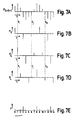
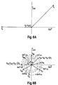
- the neighbouring relative maximum values of the main and secondary spectra are 1/3n or almost 1/3n output channels apart.; see Fig. 6A showing an echo pulse train provided with two wobbles and see also Fig. 6B for the associated DFT spectrum.
- a 15-point DFT is assumed, the 15 output channels being numbered consecutively from 0 to 14.
- the main spectrum in the case of a first-time-around echo, does not change significantly through the presence of the secondary spectra if the wobble times are sufficiently short; the secondary spectra are found to be much smaller than the main spectrum.
- the DFT spectrum together with the target range and azimuth determined by combiner circuit 5, enables to make a better distinction between first- and second/third-time-around echoes.
- three different targets are defined as being one second/third-time-around target if these targets, as viewed from the radar antenna, are behind each other at ranges corresponding with the wobble times.
- the secondary spectra in the DFT spectrum are equal in magnitude to the main spectrum, see Fig. 3E, and are respectively 1/3n and 2/3n output channels away from the main spectrum, this fact can be utilised according to the invention to prevent a faulty decision being made about the three targets at ranges corresponding with the wobble times. This may be achieved by comparing main and secondary spectra of the three targets and, to decide that "the echo is a second/third-time-around echo", by setting two additional conditions that these spectra are equal to each other and that they are 2/3n and 1/3n or zero output channels apart.
- FIG. 7A A train of n echo pulses P at range T, as obtained from the sampling, see Fig. 7A, results in general after an n-point DFT in a spectrum as shown in Fig. 3D.
- the echo pulse train of Fig. 7A may be regarded as the sum of three echo pulse trains S, Q and L, as illustrated in Figs. 7B, 7C and 7D.
- the absolute value of the DFT spectrum of echo pulse train S is indicated in Fig. 7E. This gives rise to three equivalent spectra, being 1/3n output channels apart; this is explained by Fig. 8A.
- Fig. 8A A train of n echo pulses P at range T, as obtained from the sampling, see Fig. 7A, results in general after an n-point DFT in a spectrum as shown in Fig. 3D.
- the echo pulse train of Fig. 7A may be regarded as the sum of three echo pulse trains S, Q and L, as illustrated in Figs. 7B, 7C and 7D.
- the second and third signal vectors may be regarded as the sum of three signal vectors V 2 a, V 2b , V 2 c and Vsa, V 3b , Vsc, respectively, inclined at an angle of 120 ° to each other, where:
- the associated spectrum of a second/third-time-around echo corresponds with the spectrum of Fig. 7E; here the main and secondary spectra are of equal magnitude, unlike the spectrum associated with a first-time-around echo. This explains the spectra of first-and second/third-time-around echoes.
- cluster combiner circuit 5 of the pulse radar apparatus comprises means for determining the magnitude of the local maximum values and the associated output channel number of the DFT spectrum, defined by the target-representing signal. From the range, azimuth, local maximum values and the associated output channel number of the target or targets, as determined by cluster combiner circuit 5, the classification unit 6 decides whether a target is a second/third-time-around target.
- the term i(m+1) has been added, because the pulse repetition period corresponds with (m+1) transmitter pulses, so that a k'+I(m+1)-time-around echo is suppressed in case of a k'-time-around echo.
- n should be selected sufficiently large for the n-point DFT processor.
- the pulse radar apparatus also comprises means for determining, from the DFT spectrum, information already obtained from classification unit 6 (i.e. magnitude and position of the local maximum values in the spectrum), the speed of a moving target if the target doppler frequency is greater than the average pulse repetition frequency.
- the doppler frequency of a target is equal to s P (P & 0) times the pulse repetition frequency, it is not possible to determine the doppler frequency from the associated DFT spectrum, as in such a case the doppler frequency is greater than the pulse repetition frequency (sample frequency). If however one or several wobbles are applied to the pulse repetition frequency, the value of P can be determined from the secondary spectra caused by the wobbles, even when the doppler frequency exceeds the pulse repetition frequency (P & 0). If P ⁇ 0, the dop- pier frequency is smaller than the pulse repetition frequency, and the doppler frequency can be determined directly from the DFT spectrum.
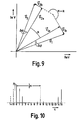
- the direction of Via and V ⁇ 2a is equal to that of the two successive signal vectors which would have been incurred if no wobble were applied to the pulse repetition frequency; the latter vectors are equal to
- the vectors having index a therefore define the main spectrum.
- the difference vectors Vi b and V 2b are a direct consequence of the application of the wobble to the pulse repetition frequency; Vib and V 2b define the secondary spectrum.
- the angular difference between two successive vectors having index a is equal to a rad. In such a case, the corresponding main spectrum will appear in or around the DFT output channel of frequency
- the angular difference between two successive vectors having index b is equal to ( ⁇ + ⁇ ) rad.
- the corresponding secondary spectrum will appear in the DFT output channel which is at a distance of hn away from the former output channel.
- the ratio Q between the magnitude of the relative maximum values of the main and secondary spectra is equal to:
- the classification unit 6 comprises means for calculating the value of Q from the ratio between the magnitude of the main and the secondary spectra, and the value of P from the value of Q.
- Classification unit 6 will proceed to the determination of P if it has previously established that the target is a first-time-around target.
- the value of P then calculated is supplied via line 8 for further processing (see Fig. 1).
- the value of P is of particular interest if P ⁇ 0, as in such a case the target doppler frequency cannot be determined from the position of the main spectrum in the DFT spectrum. If however P ⁇ 0, the doppler frequency is determinable from the position of the main spectrum in the DFT spectrum, as well as from the value of P.
- speeds of a target equal to one of the blind speeds of the radar apparatus are also measurable by determining P. In such a case, the main spectrum will be around the DFT output channel of frequency zero.
- the value of P can be determined as previously indicated.
Landscapes
- Engineering & Computer Science (AREA)
- Radar, Positioning & Navigation (AREA)
- Remote Sensing (AREA)
- Physics & Mathematics (AREA)
- Computer Networks & Wireless Communication (AREA)
- General Physics & Mathematics (AREA)
- Spectroscopy & Molecular Physics (AREA)
- Radar Systems Or Details Thereof (AREA)
Applications Claiming Priority (2)
| Application Number | Priority Date | Filing Date | Title |
|---|---|---|---|
| NL8403758A NL8403758A (nl) | 1984-12-11 | 1984-12-11 | Impulsradarapparaat. |
| NL8403758 | 1984-12-11 |
Publications (2)
| Publication Number | Publication Date |
|---|---|
| EP0187397A1 EP0187397A1 (en) | 1986-07-16 |
| EP0187397B1 true EP0187397B1 (en) | 1989-08-02 |
Family
ID=19844893
Family Applications (1)
| Application Number | Title | Priority Date | Filing Date |
|---|---|---|---|
| EP85201846A Expired EP0187397B1 (en) | 1984-12-11 | 1985-11-12 | Pulse radar apparatus |
Country Status (8)
| Country | Link |
|---|---|
| US (1) | US4679050A (enExample) |
| EP (1) | EP0187397B1 (enExample) |
| JP (1) | JPS61140881A (enExample) |
| AU (1) | AU580110B2 (enExample) |
| CA (1) | CA1246194A (enExample) |
| DE (1) | DE3572039D1 (enExample) |
| NL (1) | NL8403758A (enExample) |
| NO (1) | NO167483C (enExample) |
Families Citing this family (10)
| Publication number | Priority date | Publication date | Assignee | Title |
|---|---|---|---|---|
| US4847517A (en) * | 1988-02-16 | 1989-07-11 | Ltv Aerospace & Defense Co. | Microwave tube modulator |
| DE3933437A1 (de) * | 1989-10-06 | 1991-04-18 | Diehl Gmbh & Co | Rueckstrahlortungsanlage |
| FR2656108B1 (fr) * | 1989-12-19 | 1993-02-05 | Thomson Applic Radars Centre | Procede et systeme radar coherent a impulsions pour la detection d'unhe cible presentant des eclairs de tres courte duree. |
| FR2787199B1 (fr) * | 1998-12-11 | 2001-03-09 | Thomson Csf | Procede de detection, notamment de petites cibles marines |
| SE525699C2 (sv) * | 2003-05-05 | 2005-04-05 | Saab Ab | Anordning vid radar som arbetar med varierande pulsrepeteringsintervall |
| US7034738B1 (en) * | 2003-12-05 | 2006-04-25 | Itt Manufacturing Enterprises, Inc. | Method of radar pattern recognition by sorting signals into data clusters |
| US7397415B1 (en) | 2006-02-02 | 2008-07-08 | Itt Manufacturing Enterprises, Inc. | System and method for detecting and de-interleaving radar emitters |
| US7830297B1 (en) | 2007-12-20 | 2010-11-09 | Itt Manufacturing Enterprises, Inc. | System and method for detecting and de-interleaving radar emitters using snapshots of varying lengths |
| RU2484596C2 (ru) * | 2008-02-14 | 2013-06-10 | Нокиа Корпорейшн | Система и способ выполнения публикации |
| CN117554919B (zh) * | 2024-01-11 | 2024-03-29 | 成都金支点科技有限公司 | 一种基于双向lstm网络的雷达信号分选搜索方法 |
Family Cites Families (11)
| Publication number | Priority date | Publication date | Assignee | Title |
|---|---|---|---|---|
| NL6712495A (enExample) * | 1967-09-13 | 1969-03-17 | ||
| US3480953A (en) * | 1968-05-17 | 1969-11-25 | Us Army | Moving target indicator having staggered pulse repetition frequency |
| FR2050644A5 (enExample) * | 1969-06-19 | 1971-04-02 | Thomson Csf | |
| US3610901A (en) * | 1969-09-09 | 1971-10-05 | Emerson Electric Co | Digital modified discrete fourier transform doppler radar processor |
| US3828348A (en) * | 1971-10-21 | 1974-08-06 | Hughes Aircraft Co | System for minimizing multiple time around echos in a coherent-on-receive-doppler radar |
| NL169520C (nl) * | 1972-04-25 | 1982-07-16 | Hollandse Signaalapparaten Bv | Impulsradarapparaat. |
| US4106019A (en) * | 1972-10-05 | 1978-08-08 | Hughes Aircraft Company | Range resolving doppler radar system |
| DE2752338C2 (de) * | 1977-11-23 | 1983-11-17 | Siemens AG, 1000 Berlin und 8000 München | Radarempfänger |
| FR2411418A1 (fr) * | 1977-12-08 | 1979-07-06 | Labo Cent Telecommunicat | Procede et dispositif d'elimination des echos de retours multiples pour radars doppler a impulsions |
| NL8100606A (nl) * | 1981-02-09 | 1982-09-01 | Hollandse Signaalapparaten Bv | Impulsraderapparaat. |
| NL8101111A (nl) * | 1981-03-09 | 1982-10-01 | Hollandse Signaalapparaten Bv | Impulsradarapparaat. |
-
1984
- 1984-12-11 NL NL8403758A patent/NL8403758A/nl not_active Application Discontinuation
-
1985
- 1985-11-12 EP EP85201846A patent/EP0187397B1/en not_active Expired
- 1985-11-12 DE DE8585201846T patent/DE3572039D1/de not_active Expired
- 1985-11-19 CA CA000495650A patent/CA1246194A/en not_active Expired
- 1985-11-19 AU AU50049/85A patent/AU580110B2/en not_active Ceased
- 1985-11-25 US US06/801,367 patent/US4679050A/en not_active Expired - Fee Related
- 1985-12-09 NO NO854951A patent/NO167483C/no unknown
- 1985-12-09 JP JP60276664A patent/JPS61140881A/ja active Granted
Also Published As
| Publication number | Publication date |
|---|---|
| US4679050A (en) | 1987-07-07 |
| AU5004985A (en) | 1986-06-19 |
| JPS61140881A (ja) | 1986-06-27 |
| AU580110B2 (en) | 1989-01-05 |
| NO854951L (no) | 1986-06-12 |
| NO167483B (no) | 1991-07-29 |
| JPH045953B2 (enExample) | 1992-02-04 |
| DE3572039D1 (en) | 1989-09-07 |
| NO167483C (no) | 1991-11-06 |
| NL8403758A (nl) | 1986-07-01 |
| EP0187397A1 (en) | 1986-07-16 |
| CA1246194A (en) | 1988-12-06 |
Similar Documents
| Publication | Publication Date | Title |
|---|---|---|
| US3896434A (en) | Pulse type radar system | |
| US4042925A (en) | Pseudo-random code (PRC) surveilance radar | |
| US5923282A (en) | Radar system | |
| CA1119280A (en) | Radar system with specialized weighting | |
| US4555703A (en) | Environmental mapping system | |
| US5760734A (en) | Radar clutter removal by matrix processing | |
| US4488154A (en) | Radar processor | |
| US4649389A (en) | Stacked beam radar and target height measurement extractor especially for use therein | |
| US9465108B1 (en) | System and method for target doppler estimation and range bias compensation using high duty cycle linear frequency modulated signals | |
| US8384587B2 (en) | Radar for aerial target detection fitted to an aircraft notably for the avoidance of obstacles in flight | |
| US4339754A (en) | Spatially adaptive moving target indicator system for radar equipment | |
| US5990824A (en) | Ground based pulse radar system and method providing high clutter rejection and reliable moving target indication with extended range for airport traffic control and other applications | |
| EP0187397B1 (en) | Pulse radar apparatus | |
| US4768035A (en) | Coherent radar digital data collector and sampling technique for noncoherent transmitter radars | |
| US20240168129A1 (en) | Signal Process Technique to Reduce Radar Clutter | |
| US5115246A (en) | Radar target locating and tracking apparatus using a dual-interleaved pulse train radar waveform | |
| US3383686A (en) | Diverse frequency echo detection system with doppler frequency coherence | |
| US4644356A (en) | Bistatic coherent radar receiving system | |
| US4847622A (en) | Coherent pulse radars | |
| GB2214026A (en) | Radar apparatus employing different kinds of pulses | |
| US3879729A (en) | Moving target indicator with minimum clutter interference | |
| RU2099740C1 (ru) | Способ селекции информации о движущихся воздушных объектах с обеспечением отсева ложной трассовой радиолокационной информации и устройство для его осуществления | |
| RU2152626C1 (ru) | Радиолокационная станция с инверсным синтезированием апертуры и многочастотным зондирующим сигналом | |
| GB2298538A (en) | Dual Mode Radar System | |
| NL8102044A (nl) | Processor voor een radarstelsel. |
Legal Events
| Date | Code | Title | Description |
|---|---|---|---|
| PUAI | Public reference made under article 153(3) epc to a published international application that has entered the european phase |
Free format text: ORIGINAL CODE: 0009012 |
|
| AK | Designated contracting states |
Kind code of ref document: A1 Designated state(s): BE CH DE FR GB IT LI NL SE |
|
| 17P | Request for examination filed |
Effective date: 19860913 |
|
| 17Q | First examination report despatched |
Effective date: 19880517 |
|
| GRAA | (expected) grant |
Free format text: ORIGINAL CODE: 0009210 |
|
| AK | Designated contracting states |
Kind code of ref document: B1 Designated state(s): BE CH DE FR GB IT LI NL SE |
|
| REF | Corresponds to: |
Ref document number: 3572039 Country of ref document: DE Date of ref document: 19890907 |
|
| ET | Fr: translation filed | ||
| ITF | It: translation for a ep patent filed | ||
| PLBE | No opposition filed within time limit |
Free format text: ORIGINAL CODE: 0009261 |
|
| STAA | Information on the status of an ep patent application or granted ep patent |
Free format text: STATUS: NO OPPOSITION FILED WITHIN TIME LIMIT |
|
| 26N | No opposition filed | ||
| NLT1 | Nl: modifications of names registered in virtue of documents presented to the patent office pursuant to art. 16 a, paragraph 1 |
Owner name: HASRODE B.V. TE EINDHOVEN. |
|
| NLS | Nl: assignments of ep-patents |
Owner name: HOLLANDSE SIGNAALAPPARATEN B.V. TE HENGELO (O.). |
|
| REG | Reference to a national code |
Ref country code: GB Ref legal event code: 732 |
|
| REG | Reference to a national code |
Ref country code: FR Ref legal event code: TP Ref country code: FR Ref legal event code: CD Ref country code: FR Ref legal event code: CA |
|
| REG | Reference to a national code |
Ref country code: CH Ref legal event code: PUE Owner name: HOLLANDSE SIGNAALAPPARATEN B.V. Ref country code: CH Ref legal event code: PFA Free format text: HASRODE B.V. |
|
| BECA | Be: change of holder's address |
Free format text: 920923 *HOLLANDSE SIGNAALAPPARATEN B.V.:ZUIDELIJKE HAVENWEG 40, 7554 RR HENGELO |
|
| BECH | Be: change of holder |
Free format text: 920923 *HOLLANDSE SIGNAALAPPARATEN B.V. |
|
| ITPR | It: changes in ownership of a european patent |
Owner name: CESSIONE;HOLLANDSE SIGNAALAPPARATEN B.V. |
|
| ITTA | It: last paid annual fee | ||
| EAL | Se: european patent in force in sweden |
Ref document number: 85201846.4 |
|
| PGFP | Annual fee paid to national office [announced via postgrant information from national office to epo] |
Ref country code: DE Payment date: 19981008 Year of fee payment: 14 |
|
| PGFP | Annual fee paid to national office [announced via postgrant information from national office to epo] |
Ref country code: SE Payment date: 19981015 Year of fee payment: 14 |
|
| PGFP | Annual fee paid to national office [announced via postgrant information from national office to epo] |
Ref country code: FR Payment date: 19981023 Year of fee payment: 14 |
|
| PGFP | Annual fee paid to national office [announced via postgrant information from national office to epo] |
Ref country code: GB Payment date: 19981113 Year of fee payment: 14 |
|
| PGFP | Annual fee paid to national office [announced via postgrant information from national office to epo] |
Ref country code: BE Payment date: 19981118 Year of fee payment: 14 |
|
| PGFP | Annual fee paid to national office [announced via postgrant information from national office to epo] |
Ref country code: NL Payment date: 19981123 Year of fee payment: 14 |
|
| PGFP | Annual fee paid to national office [announced via postgrant information from national office to epo] |
Ref country code: CH Payment date: 19981210 Year of fee payment: 14 |
|
| PG25 | Lapsed in a contracting state [announced via postgrant information from national office to epo] |
Ref country code: GB Free format text: LAPSE BECAUSE OF NON-PAYMENT OF DUE FEES Effective date: 19991112 |
|
| PG25 | Lapsed in a contracting state [announced via postgrant information from national office to epo] |
Ref country code: SE Free format text: LAPSE BECAUSE OF NON-PAYMENT OF DUE FEES Effective date: 19991113 |
|
| PG25 | Lapsed in a contracting state [announced via postgrant information from national office to epo] |
Ref country code: LI Free format text: LAPSE BECAUSE OF NON-PAYMENT OF DUE FEES Effective date: 19991130 Ref country code: CH Free format text: LAPSE BECAUSE OF NON-PAYMENT OF DUE FEES Effective date: 19991130 Ref country code: BE Free format text: LAPSE BECAUSE OF NON-PAYMENT OF DUE FEES Effective date: 19991130 |
|
| BERE | Be: lapsed |
Owner name: HOLLANDSE SIGNAALAPPARATEN B.V. Effective date: 19991130 |
|
| PG25 | Lapsed in a contracting state [announced via postgrant information from national office to epo] |
Ref country code: NL Free format text: LAPSE BECAUSE OF NON-PAYMENT OF DUE FEES Effective date: 20000601 |
|
| GBPC | Gb: european patent ceased through non-payment of renewal fee |
Effective date: 19991112 |
|
| REG | Reference to a national code |
Ref country code: CH Ref legal event code: PL |
|
| EUG | Se: european patent has lapsed |
Ref document number: 85201846.4 |
|
| PG25 | Lapsed in a contracting state [announced via postgrant information from national office to epo] |
Ref country code: FR Free format text: LAPSE BECAUSE OF NON-PAYMENT OF DUE FEES Effective date: 20000731 |
|
| NLV4 | Nl: lapsed or anulled due to non-payment of the annual fee |
Effective date: 20000601 |
|
| PG25 | Lapsed in a contracting state [announced via postgrant information from national office to epo] |
Ref country code: DE Free format text: LAPSE BECAUSE OF NON-PAYMENT OF DUE FEES Effective date: 20000901 |
|
| REG | Reference to a national code |
Ref country code: FR Ref legal event code: ST |