EP0186573B1 - Detection apparatus of a gear change for the control of the operating system of a clutch starting from the control gear of an associated gear change - Google Patents
Detection apparatus of a gear change for the control of the operating system of a clutch starting from the control gear of an associated gear change Download PDFInfo
- Publication number
- EP0186573B1 EP0186573B1 EP85402462A EP85402462A EP0186573B1 EP 0186573 B1 EP0186573 B1 EP 0186573B1 EP 85402462 A EP85402462 A EP 85402462A EP 85402462 A EP85402462 A EP 85402462A EP 0186573 B1 EP0186573 B1 EP 0186573B1
- Authority
- EP
- European Patent Office
- Prior art keywords
- elements
- gear change
- clutch
- control
- limit positions
- Prior art date
- Legal status (The legal status is an assumption and is not a legal conclusion. Google has not performed a legal analysis and makes no representation as to the accuracy of the status listed.)
- Expired
Links
- 230000008859 change Effects 0.000 title claims description 25
- 238000001514 detection method Methods 0.000 title description 6
- 238000011144 upstream manufacturing Methods 0.000 claims description 20
- 238000006073 displacement reaction Methods 0.000 claims description 13
- 230000008878 coupling Effects 0.000 claims description 11
- 238000010168 coupling process Methods 0.000 claims description 11
- 238000005859 coupling reaction Methods 0.000 claims description 11
- 230000007935 neutral effect Effects 0.000 claims description 8
- 239000000523 sample Substances 0.000 description 14
- 230000004913 activation Effects 0.000 description 10
- 230000009471 action Effects 0.000 description 5
- 230000007704 transition Effects 0.000 description 5
- 238000013475 authorization Methods 0.000 description 4
- 230000003213 activating effect Effects 0.000 description 3
- 230000005540 biological transmission Effects 0.000 description 2
- 230000003287 optical effect Effects 0.000 description 2
- 230000035515 penetration Effects 0.000 description 2
- 241001433879 Camarea Species 0.000 description 1
- 230000005355 Hall effect Effects 0.000 description 1
- 238000004873 anchoring Methods 0.000 description 1
- 230000009849 deactivation Effects 0.000 description 1
- 230000000994 depressogenic effect Effects 0.000 description 1
- 230000001627 detrimental effect Effects 0.000 description 1
- 230000000694 effects Effects 0.000 description 1
- 230000001939 inductive effect Effects 0.000 description 1
- 244000045947 parasite Species 0.000 description 1
- 230000002093 peripheral effect Effects 0.000 description 1
- 230000000717 retained effect Effects 0.000 description 1
- 230000001629 suppression Effects 0.000 description 1
- 238000003466 welding Methods 0.000 description 1
Images
Classifications
-
- B—PERFORMING OPERATIONS; TRANSPORTING
- B60—VEHICLES IN GENERAL
- B60W—CONJOINT CONTROL OF VEHICLE SUB-UNITS OF DIFFERENT TYPE OR DIFFERENT FUNCTION; CONTROL SYSTEMS SPECIALLY ADAPTED FOR HYBRID VEHICLES; ROAD VEHICLE DRIVE CONTROL SYSTEMS FOR PURPOSES NOT RELATED TO THE CONTROL OF A PARTICULAR SUB-UNIT
- B60W30/00—Purposes of road vehicle drive control systems not related to the control of a particular sub-unit, e.g. of systems using conjoint control of vehicle sub-units
- B60W30/18—Propelling the vehicle
-
- B—PERFORMING OPERATIONS; TRANSPORTING
- B60—VEHICLES IN GENERAL
- B60W—CONJOINT CONTROL OF VEHICLE SUB-UNITS OF DIFFERENT TYPE OR DIFFERENT FUNCTION; CONTROL SYSTEMS SPECIALLY ADAPTED FOR HYBRID VEHICLES; ROAD VEHICLE DRIVE CONTROL SYSTEMS FOR PURPOSES NOT RELATED TO THE CONTROL OF A PARTICULAR SUB-UNIT
- B60W10/00—Conjoint control of vehicle sub-units of different type or different function
- B60W10/02—Conjoint control of vehicle sub-units of different type or different function including control of driveline clutches
-
- B—PERFORMING OPERATIONS; TRANSPORTING
- B60—VEHICLES IN GENERAL
- B60W—CONJOINT CONTROL OF VEHICLE SUB-UNITS OF DIFFERENT TYPE OR DIFFERENT FUNCTION; CONTROL SYSTEMS SPECIALLY ADAPTED FOR HYBRID VEHICLES; ROAD VEHICLE DRIVE CONTROL SYSTEMS FOR PURPOSES NOT RELATED TO THE CONTROL OF A PARTICULAR SUB-UNIT
- B60W10/00—Conjoint control of vehicle sub-units of different type or different function
- B60W10/10—Conjoint control of vehicle sub-units of different type or different function including control of change-speed gearings
Definitions
- the invention relates to the control of an automatic clutch operating system from the shift lever of a gearbox associated with this clutch. It applies in particular but not exclusively to the case of motor vehicles.
- an automatic clutch operating system is a system adapted to maneuver a clutch by itself in the direction of engagement (torque transmission) or disengagement (interruption of torque transmission) and whose the implementation is controlled by a control device adapted to apply or not an activation signal to it.
- a control device adapted to apply or not an activation signal to it.
- a system comprises an operating means such as a motor which receives, or not, an activation signal, for example of the electrical type.
- a control device for activating and deactivating a automatic clutch operating system constituted by a gearshift lever of the “broken lever” type.
- the lever consists of two generally aligned sections, one of which is a maneuvering section subjected to the action of a user and a control section connected to a gearbox by an appropriate wheelhouse.
- the maneuvering section admits a movement with respect to the control section; these two sections include two respective electrical contacts adapted to establish a circuit (or on the contrary cut it) when the operating section tilts relative to the control section under the action of a user.
- clutch control devices of this type have drawbacks, in particular that of causing disengagement of the clutch in practice as soon as the gearshift lever is pressed, and this, whatever the direction of the stress: inadvertent disengagement operations may result, which may be detrimental to the good performance of the clutch, to safety and to comfort in the case of a motor vehicle.
- the end of disengagement of the clutch is generally controlled with insufficient precision to ensure gear changes with all the flexibility desired.
- the main object of the present invention is to overcome this drawback by means of a control adapted to act only when stressed in the direction of disengagement of the engaged speed. It is also intended to allow the clutch to remain disengaged until a new gear is engaged. It also aims to allow adequate control of a system for operating a clutch without excessive wear between the elements involved, that is to say a control which has a long service life.
- the invention provides for this purpose a speed change detection device for controlling an automatic maneuvering system of a clutch from the shift lever of a gearbox associated with this clutch, of the kind comprising a first linkage element, said downstream element, admitting a travel travel between two limit positions corresponding to the engagement of gears within the gearbox and a second linkage element, said upstream element, elastically coupled to the downstream element by means of return to a neutral position, and with which is associated a displacement indicator assembly controlling an activation circuit for said automatic operating system, characterized in that said displacement indicator assembly comprises locating means adapted to identify, when the downstream element is in one of its limit positions, the direction in which a displacement of the upstream element from its neutral position causes a movement of the downstream element towards its other limit position and authorization means adapted to selectively control the activation circuit with a view to disengaging the clutch when the upstream element moves in the aforementioned direction.
- the upstream element admits a travel of travel between two limit positions corresponding respectively to the limit positions of the downstream element, and the authorization means controlling the activation circuit when the upstream element moves between its limit positions.
- the invention more particularly recommends that said displacement indicator assembly is adapted to detect and indicate the presence or not of each of said elements in one of its limit positions so that disengagement of the clutch by said automatic operating system takes place when any one of said elements is situated between its extreme positions.
- a control device advantageously causes disengagement of the clutch as long as one of the two elements of the shift lever of a gearbox associated with the clutch has not reached one of its extreme positions.
- the invention thus proposes to focus on the positions of each of the two wheelhouse elements relative to a fixed part, a chassis in practice, rather than considering, as in the case of the abovementioned “broken levers”, the relative position of these elements.
- the invention therefore makes it possible that, where appropriate, the elements under consideration do not follow one another in the gearbox maneuvering wheelhouse. However, it recommends that the position of the elements considered be detected by the same position detector, whether optical or electrical mechanics, and that, to do this, said elements are adjacent.
- the invention particularly proposes that the elements considered are pivoting elements, preferably mounted side by side on the same shaft: these elements are advantageously mounted on the gear shift shaft of the gearbox.
- the position of the two elements considered is preferably detected by a probe applied against the slices of similar cams formed on these elements; in practice, the probe admits two main configurations corresponding respectively to the activation or not of the associated operating system and, in principle, only the ramps which the cams present in order to cause the probe to pass from one to the other of these configurations need to be identical on both cams.
- a sensor can be replaced, for example by a photoelectric cell receiving a beam intercepted or not by one or the other of the elements considered, by their peripheral profile or by the edge of windows which are provided there.
- FIGS 1 to 7 show an exemplary embodiment of a speed change detection device 10 according to the invention for activating or deactivating a system 11 for operating a clutch (not shown) during a change in the configuration of the steering linkage 12 of a gearbox 13.
- the gearbox 13 comprises a casing 13A and a gear shift shaft 14 of which one end 14A exits from said casing.
- the speed change detection device 10 is mounted on this end 14A.
- This speed change detection device 10 controls the state of the automatic clutch maneuvering system 11 which, not being in itself part of the invention, is here described and shown only very schematically.
- This system 10 can be of any suitable type; it may in particular be of the type described and represented in patent FR-2 523 743 filed on March 18, 1982 or its certificate of addition FR-2541 793 filed on February 25, 1983, in the name of the applicant.
- the system 11 comprises a jack 15, the retractable rod 16 of which is articulated at its end on a lever 17 with two arms forming a clutch release fork: its left end acts for example on a stop of clutch not shown.
- the speed change detection device 10 comprises two movable linkage elements, upstream 18 and downstream 19, coupled in movement by a coupling or elastic coupling member 20 as well as an assembly position or displacement indicator 21 adapted to cooperate with the elements 18 and 19 so as to control the state of a circuit 22 for activating the automatic clutch actuation system 11.
- the circuit 22 is for example a hydraulic circuit comprising a valve 23 whose state is fixed by the position indicator assembly; in the case where the automatic clutch operating system comprises an electric motor, the activation circuit alternatively comprises a power source and a switch whose state is fixed by the position indicator assembly 21.
- the linkage elements 18 and 19 are both pivotally mounted on the projecting end 14A of the gear shift shaft 14.
- One 18 of these elements in the form of a lever with two arms, has an orifice 24 by which it is freely engaged on the end 14A of the shaft 14 as well as a window 25 for the reception of the elastic coupling member 20; it further comprises, at one of its ends, an anchoring pin 26 intended to cooperate with an element further upstream in the maneuvering wheelhouse, such as a rod 27 shown in phantom in Figure 1.
- This element 18 is controlled in position by a user acting in practice on a gear lever 28 (see FIGS. 3 to 7) located quite upstream of the steering linkage 12: the element 18 constitutes within the device 10 a driving element or actuating element.
- the other element 19, in the form of a lever with a single arm, comprises an orifice 29 through which it is engaged and secured, by welding for example, on the end 14A of the shaft 14, preferably opposite the casing 13A of the gearbox relative to the element 18 so as to prevent the latter from being able to disengage from the end 14A by axial drift.
- the element 19 forming a driven or driving element for the gear shift shaft 14 further comprises a window 30 identical to the window 25 of the element 18, these windows 25 and 30 being arranged in the same way vis- with respect to orifices 24 and 29 respectively.
- the elastic coupling of these elements 18 and 19 in pivoting is obtained by an elastic coupling means (forming a return to neutral position) engaged simultaneously in recesses made in these elements.
- a spring 20 is engaged simultaneously in the windows 25 and 30, preferably being prestressed while simultaneously pressing on the substantially radial edges which these windows present.
- the elastic coupling means is a rubber pad, billage, or the like. It should be noted that it is sufficient for this coupling means to be able to come to bear on each of the linkage elements parallel to the direction of relative movement between them. It can therefore be received in simple recesses formed in these elements, so as for example to avoid any escape of this coupling means with respect to these wheelhouse elements.
- the window 25 is formed opposite the lug 26 relative to the orifice 24 and that the shortest arm of the element 18, in which this window 25 is formed substantially the same profile as the single-arm lever that constitutes the element 19.
- the profiles of the elements 18 and 19 are substantially superposed axially (neutral relative position).
- the elements 18 and 19 admit around the gear shift shaft 14 the same angular movement between two limit positions (see FIGS. 4 and 7) for which a gear is engaged in the gearbox.
- the positions are arranged symmetrically with respect to an axial reference plane shown diagrammatically at P in FIGS. 3 to 7.
- a cylinder 31 axially oriented forming a probe, which is fixed on rods 32 adapted to penetrate more or less deeply, parallel to the plane P, in a housing 32A fixed relative to the gearbox 13A or to the chassis supporting it.
- the probe 31 forms with its sliding rods 32 and the housing 32A the aforementioned displacement indicator assembly 21; depending on the degree of penetration of the rods 32 this indicator assembly admits two reference configurations for which it is adapted to cause, or not, the activation of the automatic clutch actuation system 11.
- the degree of penetration of the rods 32 is controlled by the cam-shaped profiles presented by the sections 18A and 19A of the elements 18 and 19.
- These sections have two lateral support areas 33A and 33B or 34A and 34B, preferably centered on the shaft 14, on either side of a projecting cam area 33C or 34C, preferably concentric with the abovementioned bearing pads, to which they are connected by transition ramps 33D and 33E or 34D and 34E.
- These projecting cam zones advantageously have in their middle notches 33F or 34F forming a notch.
- the protruding cam zones occupy with the transition ramps an angular sector substantially equal, although, in practice, slightly less, than the angular movement admitted by the elements 18 and 19 between their limit positions.
- the elements 18 and 19 are aligned along the plane P.
- Their cam profiles 18A and 19A are axially superimposable and the cylinder 31 forming a probe is engaged in the dead center notches 33F or 34F and the rods 32 are pressed into the housing 32A: there is a command to disengage the associated clutch.
- the probe 31 When a gear is engaged, as shown in FIGS. 4 and 7, the probe 31 is in abutment against a lateral bearing surface of each element 33A and 34A or 33B and 34B, and the rods 32 are in configuration of extension: there is a clutch engagement command.
- the probe is also in contact or almost with the neighboring transition ramps whereby a slight rotation of any of the elements 18 and 19 is sufficient to cause, thanks to the associated ramp, a depression of the probe and its rods in the housing which causes a clutch disengagement control.
- the spring 20 under prestressing allows such an angular offset between the elements 18 and 19 only beyond a minimum torque applied to the element 19, which eliminates parasites.
- the elasticity of the spring 20 however allows that, beyond a minimum force, the element 18 can start to rotate (see FIG. 5), thus causing the probe to sink; this controls disengagement of the clutch, hence the suppression of the retaining torque applied by the latter to the input of the gearbox: the gearshift shaft is released, as well as the element 19 and the spring 20 causes them to catch up with their angular delay relative to the actuating element 18.
- the upstream actuating element 18 reaches without resistance in its other limit position, but it sometimes happens that the corresponding speed is difficult to engage: the gearshift shaft therefore remains below its final position. It is the same for element 19 which, thanks to the compressibility of spring 20, can take a slight delay on the element 18. As it appears in FIG. 6, the element 19 maintains the probe in the depressed condition: the clutch therefore remains disengaged as long as the gearshift shaft does not did not actually reach final configuration.
- the cam profile of the upstream element 18 constitutes, thanks to its ramps 33D and 33E, marking means adapted to identify the direction in which the upstream element must move, from from its neutral position relative to the downstream element, to cause movement of the downstream element from one of its limit positions towards the other; in fact, when the upstream element is in one of its limit positions, there is only one ramp in the vicinity of the probe, arranged relative to the latter in the direction of movement towards the other limit position; these ramps constitute, with the probe 31 and the section 33C, authorization means suitable for controlling the activation circuit 22 when the upstream element moves in the "right direction.”
- the role of the lateral areas of these sections is mainly to prevent the probe and its rods 32 from protruding too much from the housing 32A: it may suffice that there are only end areas on a single element , or even on no element if the rods 32 are sufficiently retained in the housing in the event of extension. In a variant not shown, it is the lateral areas of the edges of the elements 18 and 19 which are projecting.
- the above description has been offered for information only and that many variant embodiments can be proposed by those skilled in the art without departing from the scope of the invention, so far as concerns the shape of the wheelhouse elements considered (bent levers or other) only with regard to the nature of the associated displacement detector assembly and of its means of location and authorization.
- the coupling member can be of any suitable nature.
- the elements with which the displacement indicator assembly is associated can be dissociated from one another and with respect to the gearshift shaft; they can be rods in linear movement: the displacement indicator assembly can be split so as to separately test the presence or not of each of the elements in a limit position.
- the displacement indicator assembly is adapted to test the presence or not of the only upstream element in a limit position.
- This displacement indicator assembly can be of any kind; it can include an electronic sensor (analog, potentiometer, Hall effect sensor, inductive sensor for example) or also an optical sensor with holes in the elements which only come into alignment with a light source simultaneously if these elements are in the appropriate position .
Landscapes
- Engineering & Computer Science (AREA)
- Transportation (AREA)
- Mechanical Engineering (AREA)
- Chemical & Material Sciences (AREA)
- Combustion & Propulsion (AREA)
- Automation & Control Theory (AREA)
- Control Of Transmission Device (AREA)
Description
L'invention concerne la commande d'un système de manoeuvre automatique d'un embrayage à partir de la timonerie de manoeuvre d'une boîte de vitesse associée à cet embrayage. Elle s'applique notamment mais non exclusivement au cas de véhicules automobiles.The invention relates to the control of an automatic clutch operating system from the shift lever of a gearbox associated with this clutch. It applies in particular but not exclusively to the case of motor vehicles.
Ainsi qu'on le sait un système de manoeuvre automatique pour embrayage est un système adapté à manoeuvrer par lui-même un embrayage dans le sens de l'engagement (transmission de couple) ou du désengagement (interruption de la transmission de couple) et dont la mise en oeuvre est commandée par un dispositif de commande adapté à lui appliquer ou non un signal d'activation. Le plus souvent, un tel système comporte un moyen de manoeuvre tel qu'un moteur qui reçoit, ou non, un signal d'activation, par exemple de type électrique.As is known, an automatic clutch operating system is a system adapted to maneuver a clutch by itself in the direction of engagement (torque transmission) or disengagement (interruption of torque transmission) and whose the implementation is controlled by a control device adapted to apply or not an activation signal to it. Most often, such a system comprises an operating means such as a motor which receives, or not, an activation signal, for example of the electrical type.
On connaît déjà, d'après le brevet FR-A-1 075 404 demandé le 23 février 1953 ou son addition FR-E-66197 demandée le 13 juillet 1954, un dispositif de commande, pour l'activation et la désactivation d'un système de manoeuvre automatique d'embrayage, constitué par un levier de changement de vitesse du type « levier cassé •. Le levier se compose de deux tronçons globalement alignés, dont un tronçon- de manoeuvre soumis à l'action d'un usager et un tronçon de commande relié à une boîte de vitesse par une timonerie de manoeuvre appropriée. Le tronçon de manoeuvre admet un débattement vis-à-vis du tronçon de commande ; ces deux tronçons comportent deux contacts électriques respectifs adaptés à venir établir un circuit (ou au contraire le couper) lorsque le tronçon de manoeuvre s'incline par rapport au tronçon de commande sous l'action d'un usager.Already known, from patent FR-A-1,075,404 applied for on February 23, 1953 or its addition FR-E-66197 applied for on July 13, 1954, a control device for activating and deactivating a automatic clutch operating system, constituted by a gearshift lever of the “broken lever” type. The lever consists of two generally aligned sections, one of which is a maneuvering section subjected to the action of a user and a control section connected to a gearbox by an appropriate wheelhouse. The maneuvering section admits a movement with respect to the control section; these two sections include two respective electrical contacts adapted to establish a circuit (or on the contrary cut it) when the operating section tilts relative to the control section under the action of a user.
En fait les dispositifs de commande d'embrayage de ce type présentent des inconvénients, celui notamment de provoquer en pratique un désengagement de l'embrayage dès que le levier de changement de vitesse est sollicité, et ce, quel que soit notamment le sens de la sollicitation : il peut en résulter des opérations intempestives de désengagement qui peuvent se révéler préjudiciables à la bonne tenue de l'embrayage, à la sécurité et au confort dans le cas d'un véhicule automobile. En outre, dans ces dispositifs, la fin du désengagement de l'embrayage est généralement contrôlée avec une précision insuffisante pour assurer des changements de vitesse avec toute la souplesse désirée.In fact, clutch control devices of this type have drawbacks, in particular that of causing disengagement of the clutch in practice as soon as the gearshift lever is pressed, and this, whatever the direction of the stress: inadvertent disengagement operations may result, which may be detrimental to the good performance of the clutch, to safety and to comfort in the case of a motor vehicle. In addition, in these devices, the end of disengagement of the clutch is generally controlled with insufficient precision to ensure gear changes with all the flexibility desired.
La présente invention a pour principal objet de pallier cet inconvénient grâce à une commande adaptée à n'agir que lors d'une sollicitation dans le sens de désengagement de la vitesse enclenchée. Elle a également pour objet de permettre que l'embrayage reste désengagé tant qu'une nouvelle vitesse n'est pas engagée. Elle a aussi pour objet de permettre une commande adéquate d'un système de manoeuvre d'un embrayage sans usure exagérée entre les éléments qui interviennent, c'est-à-dire une commande qui présente une grande longévité dans ses performances.The main object of the present invention is to overcome this drawback by means of a control adapted to act only when stressed in the direction of disengagement of the engaged speed. It is also intended to allow the clutch to remain disengaged until a new gear is engaged. It also aims to allow adequate control of a system for operating a clutch without excessive wear between the elements involved, that is to say a control which has a long service life.
L'invention propose à cet effet un dispositif de détection de changement de vitesse pour la commande d'un système de manœuvreautomati- que d'un embrayage à partir de la timonerie de manoeuvre d'une boîte de vitesse associée à cet embrayage, du genre comportant un premier élément de timonerie, dit élément aval, admettant une course de débattement entre deux positions limites correspondant à l'engagement de vitesses au sein de la boîte de vitesse et un second élément de timonerie, dit élément amont, attelé élastiquement à l'élément aval par des moyens de rappel en une position neutre, et auquel est associé un ensemble indicateur de déplacement commandant un circuit d'activation pour ledit système de manoeuvre automatique, caractérisé en ce que ledit ensemble indicateur de déplacement comporte des moyens de repérage adaptés à repérer, lorsque l'élément aval est en une de ses positions limites, le sens dans lequel un déplacement de l'élément amont à partir de sa position neutre provoque un mouvement de l'élément aval vers son autre position limite et des moyens d'autorisation adaptés à commander sélectivement le circuit d'activation en vue d'un désengagement de l'embrayage lorsque l'élément amont se déplace dans le sens précité.The invention provides for this purpose a speed change detection device for controlling an automatic maneuvering system of a clutch from the shift lever of a gearbox associated with this clutch, of the kind comprising a first linkage element, said downstream element, admitting a travel travel between two limit positions corresponding to the engagement of gears within the gearbox and a second linkage element, said upstream element, elastically coupled to the downstream element by means of return to a neutral position, and with which is associated a displacement indicator assembly controlling an activation circuit for said automatic operating system, characterized in that said displacement indicator assembly comprises locating means adapted to identify, when the downstream element is in one of its limit positions, the direction in which a displacement of the upstream element from its neutral position causes a movement of the downstream element towards its other limit position and authorization means adapted to selectively control the activation circuit with a view to disengaging the clutch when the upstream element moves in the aforementioned direction.
Dans un mode préféré de réalisation de l'invention, l'élément amont admet une course de débattement entre deux positions limites correspondant respectivement aux positions limites de l'élément aval, et les moyens d'autorisation commandant le circuit d'activation lorsque l'élément amont se déplace entre ses positions limites. L'invention préconise plus particulièrement que ledit ensemble indicateur de déplacement soit adapté à détecter et indiquer la présence ou non de chacun desdits éléments en l'une de ses positions limites en sorte qu'un désengagement de l'embrayage par ledit système de manoeuvre automatique ait lieu lorsque l'un quelconque desdits éléments est situé entre ses positions extrêmes.In a preferred embodiment of the invention, the upstream element admits a travel of travel between two limit positions corresponding respectively to the limit positions of the downstream element, and the authorization means controlling the activation circuit when the upstream element moves between its limit positions. The invention more particularly recommends that said displacement indicator assembly is adapted to detect and indicate the presence or not of each of said elements in one of its limit positions so that disengagement of the clutch by said automatic operating system takes place when any one of said elements is situated between its extreme positions.
On notera qu'un dispositif de commande selon l'invention provoque avantageusement un désengagement de l'embrayage tant que l'un de deux éléments de la timonerie de manoeuvre d'une boîte de vitesse associée à l'embrayage n'est pas parvenu en l'une de ses positions extrêmes. L'invention propose ainsi de s'intéresser aux positions de chacun de deux éléments de timonerie par rapport à une pièce fixe, un châssis en pratique, plutôt que de considérer, comme dans le cas des leviers « cassés précités, la position relative de ces éléments. L'invention permet donc que, le cas échéant, les éléments considérés ne se suivent pas dans la timonerie de manoeuvre de la boîte de vitesse. Elle préconise toutefois que la position des éléments considérés soit détectée par un même détecteur de position, qu'il soit mécanique optique ou électrique, et que, pour ce faire, lesdits éléments soient adjacents. L'invention propose tout particulièrement que les éléments considérés soient des éléments pivotants, de préférence montés côte à côte sur un même arbre : ces éléments sont avantageusement montés sur l'arbre de passage de vitesse de la boîte de vitesse. La position des deux éléments considérés est de préférence détectée par un palpeur appliqué contre les tranches de cames similaires ménagées sur ces éléments ; en pratique le palpeur admet deux configurations principales correspondant respectivement à l'activation ou non du système de manoeuvre associé et, en principe, seules les rampes que présentent les cames en vue de faire passer le palpeur de l'une à l'autre de ces configurations ont besoin d'être identiques sur les deux cames. Un tel capteur peut être remplacé, par exemple par une cellule photoélec- trique recevant un rayon intercepté ou non par l'un ou l'autre des éléments considérés, par leur profil périphérique ou par le bord de fenêtres qui y sont ménagées.It will be noted that a control device according to the invention advantageously causes disengagement of the clutch as long as one of the two elements of the shift lever of a gearbox associated with the clutch has not reached one of its extreme positions. The invention thus proposes to focus on the positions of each of the two wheelhouse elements relative to a fixed part, a chassis in practice, rather than considering, as in the case of the abovementioned “broken levers”, the relative position of these elements. The invention therefore makes it possible that, where appropriate, the elements under consideration do not follow one another in the gearbox maneuvering wheelhouse. However, it recommends that the position of the elements considered be detected by the same position detector, whether optical or electrical mechanics, and that, to do this, said elements are adjacent. The invention particularly proposes that the elements considered are pivoting elements, preferably mounted side by side on the same shaft: these elements are advantageously mounted on the gear shift shaft of the gearbox. The position of the two elements considered is preferably detected by a probe applied against the slices of similar cams formed on these elements; in practice, the probe admits two main configurations corresponding respectively to the activation or not of the associated operating system and, in principle, only the ramps which the cams present in order to cause the probe to pass from one to the other of these configurations need to be identical on both cams. Such a sensor can be replaced, for example by a photoelectric cell receiving a beam intercepted or not by one or the other of the elements considered, by their peripheral profile or by the edge of windows which are provided there.
D'autres objets, caractéristiques et avantages de l'invention ressortent de la description qui suit, donnée à titre d'exemple non limitatif en regard des dessins annexés sur lesquels :
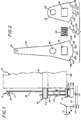
- - la figure 1 est une vue latérale schématique en coupe d'un dispositif de commande selon l'invention, monté en un bout de l'arbre de passage de vitesse d'une boîte de vitesse ;
- - la figure 2 en est une vue éclatée de face ;
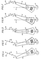
- - la figure 3 en est une vue schématique de face en configuration de repos ;
- - la figure 4 en est une vue schématique de face lorsqu'une première vitesse est engagée ;
- - la figure 5 en est une vue schématiquè de face au début d'une manoeuvre de changement de vitesse ;
- - la figure 6 en est une vue schématique de face vers la fin de ladite manoeuvre de changement de vitesse ; et
- - la figure 7 en est une vue schématique de face à la fin de ladite manoeuvre de changement de vitesse, lorsqu'une seconde vitesse est engagée.
- - Figure 1 is a schematic sectional side view of a control device according to the invention, mounted at one end of the gear shift shaft of a gearbox;
- - Figure 2 is an exploded front view;
- - Figure 3 is a schematic front view in the rest configuration;
- - Figure 4 is a schematic front view when a first gear is engaged;
- - Figure 5 is a schematic front view at the start of a speed change maneuver;
- - Figure 6 is a schematic front view towards the end of said speed change maneuver; and
- - Figure 7 is a schematic front view at the end of said gear change maneuver, when a second gear is engaged.
Les figures 1 à 7 représentent un exemple de réalisation d'un dispositif 10 de détection de changement de vitesse selon l'invention pour l'activation ou la désactivation d'un système 11 de manoeuvre d'un embrayage (non représenté) lors d'un changement dans la configuration de la timonerie de manoeuvre 12 d'une boîte de vitesse 13.Figures 1 to 7 show an exemplary embodiment of a speed
A la figure 1 la boîte de vitesse 13 comporte un carter 13A et un arbre de passage de vitesse 14 dont une extrémité 14A sort dudit carter. Dans le mode de réalisation préféré de l'invention représenté aux figures 1 à 7 le dispositif 10 de détection de changement de vitesse est monté sur cette extrémité 14A.In FIG. 1 the
Ce dispositif 10 de détection de changement de vitesse contrôle l'état du système 11 de manoeuvre automatique d'embrayage qui, ne faisant pas partie en lui-même de l'invention, n'est ici décrit et représenté que de façon très schématique. Ce système 10 peut être de tout type approprié ; il peut notamment être du type décrit et représenté dans le brevet FR-2 523 743 déposé le 18 mars 1982 ou son certificat d'addition FR-2541 793 déposé le 25 février 1983, au nom de la demanderesse. Tel que représenté à la figure 1 à titre de variante le système 11 comporte un vérin 15 dont la tige rétractable 16 est articulée en son extrémité sur un levier 17 à deux bras formant fourchette de débrayage : son extrémité gauche agit par exemple sur une butée de débrayage non représentée.This speed
Tel que représenté aux figures 1 et 2 le dispositif 10 de détection de changement de vitesse comporte deux éléments mobiles de timonerie, amont 18 et aval 19, accouplés en mouvement par un organe 20 d'attelage ou d'accouplement élastique ainsi qu'un ensemble indicateur de position ou de déplacement 21 adapté à coopérer avec les éléments 18 et 19 en sorte de contrôler l'état d'un circuit 22 d'activation du système 11 de manosu- vre automatique d'embrayage. Le circuit 22 est par exemple un circuit hydraulique comportant une valve 23 dont l'état est fixé par l'ensemble indicateur de position ; dans le cas où le système de manoeuvre automatique d'embrayage comporte un moteur électrique, le circuit d'activation comporte en variante une source d'alimentation et un interrupteur dont l'état est fixé par l'ensemble indicateur de position 21.As shown in FIGS. 1 and 2, the speed
Les éléments de timonerie 18 et 19 sont tous deux montés pivotants sur l'extrémité en saillie 14A de l'arbre de passage de vitesse 14. L'un 18 de ces éléments, en forme de levier à deux bras, comporte un orifice 24 par lequel il est engagé librement sur l'extrémité 14A de l'arbre 14 ainsi qu'une fenêtre 25 pour la réception de l'organe 20 d'accouplement élastique ; il comporte en outre, en une de ses extrémités, un ergot d'ancrage 26 destiné à coopérer avec un élément plus en amont dans la timonerie de manoeuvre, tel qu'une tringle 27 représentée en traits mixtes à la figure 1. Cet élément 18 est commandé en position par un usager agissant en pratique sur un levier de vitesse 28 (voir figures 3 à 7) situé tout à fait en amont de la timonerie de manoeuvre 12 : l'élément 18 constitue au sein du dispositif 10 un élément menant ou élément d'actionnement. L'autre élément 19, en forme de levier à un seul bras, comporte un orifice 29 par lequel il est engagé et assujetti, par soudure par exemple, sur l'extrémité 14A de l'arbre 14, de préférence à l'opposé du carter 13A de la boîte de vitesse par rapport à l'élément 18 en sorte d'empêcher que ce dernier ne puisse se dégager de l'extrémité 14A par dérive axiale. L'élément 19 formant élément mené ou d'entraînement pour l'arbre 14 de passage de vitesse comporte en outre une fenêtre 30 identique à la fenêtre 25 de l'élément 18, ces fenêtres 25 et 30 étant disposées de la même manière vis-à-vis respectivement des orifices 24 et 29.The
L'accouplement élastique de ces éléments 18 et 19 en pivotement est obtenu par un moyen d'accouplement élastique (formant organe de rappel en position neutre) engagé simultanément dans des évidements réalisés dans ces éléments. En effet un ressort 20 est engagé simultanément dans les fenêtres 25 et 30 en étant de préférence précontraint en appui simultané sur les tranches sensiblement radiales que présentent ces fenêtres. En variantes non représentées le moyen d'accouplement élastique est un plot en caoutchouc, un billage, ou analogues. Il est à noter qu'il suffit que ce moyen d'accouplement puisse venir prendre appui sur chacun des éléments de timonerie parallèlement à la direction de débattement relatif entre ceux-ci. Il peut donc être reçu dans de simples creux ménagés dans ces éléments, de manière par exemple à éviter tout échappement de ce moyen d'accouplement vis-à-vis de ces éléments de timonerie.The elastic coupling of these
On notera que dans l'exemple représenté la fenêtre 25 est ménagée à l'opposé de l'ergot 26 par rapport à l'orifice 24 et que le bras le plus court de l'élément 18, dans lequel est ménagé cette fenêtre 25 a sensiblement le même profil que le levier à un seul bras que constitue l'élément 19. En position de repos du ressort 20 les profils des éléments 18 et 19 sont sensiblement superposés axialement (position relative neutre).It will be noted that in the example shown the
Les éléments 18 et 19 admettent autour de l'arbre 14 de passage de vitesse un même débattement angulaire entre deux positions limites (voir figures 4 et 7) pour lesquelles une vitesse est engagée dans la boîte de vitesse. Les positions sont disposées de façon symétrique par rapport à un plan axial de référence schématisé en P aux figures 3 à 7.The
Dans ce plan est disposé, en regard des tranches 18A et 19A des éléments 18 et 19, un cylindre 31 orienté axialement formant palpeur, qui est fixé sur des tiges 32 adaptées à pénétrer plus ou moins profondément, parallèlement au plan P, dans un boîtier 32A fixe par rapport au carter 13A de la boite de vitesse ou au châssis le supportant. Le palpeur 31 forme avec ses tiges coulissantes 32 et le boîtier 32A l'ensemble indicateur de déplacement 21 précité ; selon le degré d'enfoncement des tiges 32 cet ensemble indicateur admet deux configurations de référence pour lesquelles il est adapté à provoquer, ou non, l'activation du système 11 de manoeuvre automatique d'embrayage.In this plane is arranged, opposite the
Le degré d'enfoncement des tiges 32 est contrôlé par les profils en forme de came que présentent les tranches 18A et 19A des éléments 18 et 19. Ces tranches présentent deux plages latérales d'appui 33A et 33B ou 34A et 34B, de préférence centrées sur l'arbre 14, de part et d'autre d'une zone de came en saillie 33C ou 34C, de préférence concentriques aux plages d'appui précitées, à laquelle elles se raccordent par des rampes de transition 33D et 33E ou 34D et 34E. Ces zones de came en saillie présentent avantageusement en leur milieu des encoches 33F ou 34F formant cran de point mort. Les zones de came en saillie occupent avec les rampes de transition un secteur angulaire sensiblement égal, quoique, en pratique, légèrement inférieur, au débattement angulaire qu'admettent les éléments 18 et 19 entre leurs positions limites.The degree of penetration of the
En configuration de point mort de la boîte de vitesse, telle qu'elle est représentée à la figure 3, les éléments 18 et 19 sont alignés selon le plan P. Leurs profils de came 18A et 19A sont superposables axialement et le cylindre 31 formant palpeur est engagé dans les crans de point mort 33F ou 34F et les tiges 32 sont enfoncées dans le boîtier 32A : il y a commande en désengagement de l'embrayage associé.In the gearbox neutral position configuration, as shown in FIG. 3, the
Lorsqu'une vitesse est engagée, comme cela est représenté aux figures 4 et 7, le palpeur 31 est en appui contre une plage latérale d'appui de chaque élément 33A et 34A ou 33B et 34B, et les tiges 32 sont en configuration d'extension : il y a commande en engagement de l'embrayage. De façon avantageuse le palpeur est également en contact ou presque avec les rampes de transition avoisinantes grâce à quoi une faible rotation de l'un quelconque des éléments 18 et 19 suffit à provoquer, grâce à la rampe associée, un enfoncement du palpeur et de ses tiges dans le boîtier ce qui provoque une commande en désengagement de l'embrayage. Il est à noter que le ressort 20 sous précontrainte ne permet un tel décalage angulaire entre les éléments 18 et 19 qu'au-delà d'un couple minimum appliqué à l'élément 19, ce qui élimine les parasites.When a gear is engaged, as shown in FIGS. 4 and 7, the
Lorsque, à partir de la configuration de la figure 4, la timonerie 12 de manoeuvre de la boîte de vitesse est sollicitée dans le sens d'un changement de vitesse, deux cas peuvent apparaître. En l'absence de couple de retenue appliqué à la boîte de vitesse, l'arbre de passage de vitesse 14 est libre de tourner et l'élément amont d'actionnement 18, ainsi que l'élément aval d'entraînement 19, peuvent quitter sans résistance leurs positions limites correspondant à la vitesse engagée jusque-là. Par leurs rampes de transition 33D et 34D ces éléments provoquent tous deux par action sur le palpeur 31 un enfoncement des tiges 32 dans le boîtier d'où une commande en désengagement de l'embrayage. Par contre lorsque la boîte de vitesse transmet un couple d'entraînement, l'arbre de passage de vitesse 14 et l'élément 19 restent généralement bloqués en position. L'élasticité du ressort 20 permet toutefois que, au-delà d'un effort minimum, l'élément 18 puisse commencer à tourner (voir figure 5), provoquant ainsi l'enfoncement du palpeur ; cela commande un désengagement de l'embrayage, d'où une suppression du couple de retenue appliqué par celui-ci à l'entrée de la boîte de vitesse : l'arbre de passage de vitesse se débloque, ainsi que l'élément 19 et le ressort 20 provoque le rattrapage par ceux-ci de leur retard angulaire par rapport à l'élément d'actionnement 18.When, from the configuration of FIG. 4, the wheelhouse 12 for operating the gearbox is biased in the direction of a gear change, two cases may appear. In the absence of a holding torque applied to the gearbox, the
En fin de course l'élément amont d'actionnement 18 parvient sans résistance en son autre position limite mais il arrive parfois que la vitesse correspondante soit difficile à engager : l'arbre de passage de vitesse reste donc en deçà de sa position finale. Il en est de même de l'élément 19 qui, grâce à la compressibilité du ressort 20, peut prendre un léger retard sur l'élément 18. Ainsi qu'il apparaît à la figure 6, l'élément 19 maintient le palpeur en condition d'enfoncement : l'embrayage reste donc désengagé tant que l'arbre de passage de vitesse n'est pas effectivement parvenu en configuration finale.At the end of the stroke, the
On appréciera qu'une action sur le levier de changement de vitesse dans le sens tendant à engager une vitesse déjà engagée n'a pas d'action sur le dispositif 10, ce qui élimine des ordres de débrayage intempestifs.It will be appreciated that an action on the speed change lever in the direction tending to engage a speed already engaged has no action on the
Cela peut s'expliquer par le fait que le profil en came de l'élément amont 18 constitue, grâce à ses rampes 33D et 33E, des moyens de repérage adaptés à identifier le sens dans lequel l'élément amont doit se déplacer, à partir de sa position neutre par rapport à l'élément aval, pour provoquer un mouvement de l'élément aval depuis l'une de ses positions limites vers l'autre ; en effet, lorsque l'élément amont est dans l'une de ses positions limites, il n'y a qu'une seule rampe au voisinage du palpeur, disposée par rapport à celui-ci dans le sens d'un déplacement vers l'autre position limite ; ces rampes constituent avec le palpeur 31 et la tranche 33C des moyens d'autorisation adaptés à commander le circuit d'activation 22 lorsque l'élément amont se déplace dans le « bon sens.This can be explained by the fact that the cam profile of the
On notera que le bon contrôle des moments où l'embrayage doit être désengagé ou réengagé par le système 11 de manoeuvre automatique dépend essentiellement des rampes de transition et de leur proche voisinage sur les zones de cames des tranches 18A et 19A. Ce sont donc essentiellement ces rampes et ces proches voisinages qui doivent être globalement superposés en condition de repos et les zones de cames en saillies peuvent présenter ailleurs des profils différents sur les deux éléments. En fait ces rampes peuvent avoir une même inclinaison mais des longueurs différentes. On notera par ailleurs que le rôle des plages latérales de ces tranches est principalement d'empêcher que le palpeur et ses tiges 32 ne sortent trop du boîtier 32A : il peut suffire qu'il n'y ait de plages terminales que sur un seul élément, voire sur aucun élément si les tiges 32 sont suffisamment retenues dans le boîtier en cas d'extension. En variante non représentée ce sont les plages latérales des tranches des éléments 18 et 19 qui sont en saillie.It will be noted that the proper control of the moments when the clutch must be disengaged or re-engaged by the
Il va de soi que la description qui précède n'a été proposée qu'à titre indicatif et que de nombreuses variantes de réalisation peuvent être proposées par l'Homme de l'art sans sortir du cadre de l'invention tant en ce qui concerne la forme des éléments de timonerie considérés (leviers coudés ou autres) qu'en ce qui concerne la nature de l'ensemble détecteur de déplacement associé et de ses moyens de repérage et d'autorisation. Ainsi, pour gagner de la place, on peut ménager les fenêtres de réception du ressort 20 entre l'arbre de passage de vitesse et le point d'attelage 26 au reste de la timonerie. L'organe d'accouplement peut être de toute nature appropriée. Les éléments auxquels est associé l'ensemble indicateur de déplacement peuvent être dissociés l'un de l'autre et vis-à-vis de l'arbre de passage de vitesse ; il peut s'agir de tringles en mouvement linéaire : l'ensemble indicateur de déplacement peut être dédoublé en sorte de tester séparément la présence ou non de chacun des éléments en une position limite. En fait il suffit, dans une version simplifiée de l'invention, que l'ensemble indicateur de déplacement soit adapté à tester la présence ou non du seul élément amont en une position limite. Cet ensemble indicateur de déplacement peut être de toute nature ; il peut comporter un capteur électronique (analogique, potentiomètre, capteur à effet Hall, capteur inductif par exemple) ou aussi un capteur optique avec des perçages dans les éléments qui ne viennent simultanément en alignement avec une source lumineuse que si ces éléments sont en position appropriée.It goes without saying that the above description has been offered for information only and that many variant embodiments can be proposed by those skilled in the art without departing from the scope of the invention, so far as concerns the shape of the wheelhouse elements considered (bent levers or other) only with regard to the nature of the associated displacement detector assembly and of its means of location and authorization. Thus, to save space, one can arrange the receiving windows of the
En fait, les moments où l'activation ou la désactivation du système de manoeuvre automatique de l'embrayage est provoquée dépendent bien sûr de l'effet qu'a ce système sur l'embrayage (engagement ou désengagement).In fact, the times when the activation or deactivation of the automatic clutch operating system is caused depend of course on the effect that this system has on the clutch (engagement or disengagement).
Claims (12)
Applications Claiming Priority (2)
| Application Number | Priority Date | Filing Date | Title |
|---|---|---|---|
| FR8419082 | 1984-12-13 | ||
| FR8419082A FR2574720B1 (en) | 1984-12-13 | 1984-12-13 | SPEED CHANGE DETECTION DEVICE FOR CONTROLLING A CLUTCH SHIFT SYSTEM FROM THE SHIFT WHEEL OF AN ASSOCIATED GEARBOX |
Publications (2)
| Publication Number | Publication Date |
|---|---|
| EP0186573A1 EP0186573A1 (en) | 1986-07-02 |
| EP0186573B1 true EP0186573B1 (en) | 1988-07-27 |
Family
ID=9310561
Family Applications (1)
| Application Number | Title | Priority Date | Filing Date |
|---|---|---|---|
| EP85402462A Expired EP0186573B1 (en) | 1984-12-13 | 1985-12-11 | Detection apparatus of a gear change for the control of the operating system of a clutch starting from the control gear of an associated gear change |
Country Status (3)
| Country | Link |
|---|---|
| EP (1) | EP0186573B1 (en) |
| DE (1) | DE3563935D1 (en) |
| FR (1) | FR2574720B1 (en) |
Families Citing this family (2)
| Publication number | Priority date | Publication date | Assignee | Title |
|---|---|---|---|---|
| FR2643316B1 (en) * | 1989-02-17 | 1993-09-10 | Valeo | SPEED DETECTION DEVICE FOR CONTROLLING A CLUTCH ASSOCIATED WITH A GEARBOX |
| US5490434A (en) * | 1994-01-28 | 1996-02-13 | Grand Haven Stamped Products | Vehicle transfer case shifter system |
Family Cites Families (5)
| Publication number | Priority date | Publication date | Assignee | Title |
|---|---|---|---|---|
| US1685502A (en) * | 1925-02-09 | 1928-09-25 | Twin Disc Clutch Co | Clutch and transmission mechanism |
| FR1115791A (en) * | 1954-12-06 | 1956-04-30 | Citroen Sa Andre | Improvements to clutch mechanisms |
| US3993175A (en) * | 1974-10-23 | 1976-11-23 | Fiat-Allis Construction Machinery, Inc. | Control lever assembly for power shift transmission and modulating clutch |
| DE3229369A1 (en) * | 1982-08-06 | 1984-02-09 | Sachs Systemtechnik Gmbh | FRICTION COUPLING FOR INTERNAL COMMERCIAL ENGINE DRIVEN VEHICLES |
| US4610335A (en) * | 1982-11-10 | 1986-09-09 | Honda Giken Kogyo Kabushiki Kaisha | Control device for clutch and transmission in vehicles |
-
1984
- 1984-12-13 FR FR8419082A patent/FR2574720B1/en not_active Expired
-
1985
- 1985-12-11 EP EP85402462A patent/EP0186573B1/en not_active Expired
- 1985-12-11 DE DE8585402462T patent/DE3563935D1/en not_active Expired
Also Published As
| Publication number | Publication date |
|---|---|
| DE3563935D1 (en) | 1988-09-01 |
| EP0186573A1 (en) | 1986-07-02 |
| FR2574720A1 (en) | 1986-06-20 |
| FR2574720B1 (en) | 1987-02-27 |
Similar Documents
| Publication | Publication Date | Title |
|---|---|---|
| EP0189338B1 (en) | Device for the detection of gear changing for a clutch control system linked to a gearbox | |
| EP0220092B1 (en) | Control device for a coupling means such as a clutch or a gear box or a brake or the like | |
| FR2589545A1 (en) | PARKING DEVICE FOR AUTOMATIC TRANSMISSION | |
| WO2013007924A2 (en) | Device for controlling a gearbox and a parking brake of a motor vehicle, using a common operating lever | |
| FR2530757A1 (en) | FRICTION CLUTCH CONTROL | |
| EP0624741B1 (en) | Gear shift device for an automatic automotive gearbox | |
| FR2964925A1 (en) | Parking brake for robotized gear box to safely park vehicle, has automatic parking control unit that acts on mobile latch in locking direction of locking body when gear ratio selector is in neutral position | |
| EP0186573B1 (en) | Detection apparatus of a gear change for the control of the operating system of a clutch starting from the control gear of an associated gear change | |
| EP0383688B1 (en) | Manual gearbox ratio-detecting device associated with a linkage of a control system for an automatic clutch | |
| EP0420738B1 (en) | Transmission control linkwork for motor vehicles | |
| EP0186537B1 (en) | Disc brake | |
| FR2704616A1 (en) | Gearshift device for a gearbox of a motor vehicle. | |
| EP0734496B1 (en) | Automatic adjusting strut for drum brake | |
| FR2735551A1 (en) | LOCKING DEVICE FOR MECHANICAL GEARBOX | |
| WO2019215405A1 (en) | System for ejecting tips of sampling pipettes with improved ergonomics | |
| EP0751322A1 (en) | Vehicle gear selector lever with force sensor | |
| FR2703422A1 (en) | Gearshift device for a gearbox of a motor vehicle. | |
| FR2611837A1 (en) | Device for actuating a clutch with control | |
| EP0225211B1 (en) | Safety device for a reverse gear change control with an articulated handle | |
| EP1179463A1 (en) | Control device of an electric parking brake comprising a transducer | |
| FR2579703A1 (en) | CLUTCHING STOP, IN PARTICULAR FOR MOTOR VEHICLE | |
| FR2782036A1 (en) | MANUAL CONTROL DEVICE OF A FUNCTIONAL BODY, ASSOCIATED WITH A LEVER, ESPECIALLY THE ACTUATION LEVER OF A GEARBOX | |
| FR2722262A1 (en) | Control assembly for motor vehicle clutch release mechanism | |
| FR2823821A1 (en) | Automobile automatic gearbox control comprises selector articulated on support and selector guides connected by common bascule to selector and support | |
| EP0349368B1 (en) | Adjustable disc brake |
Legal Events
| Date | Code | Title | Description |
|---|---|---|---|
| PUAI | Public reference made under article 153(3) epc to a published international application that has entered the european phase |
Free format text: ORIGINAL CODE: 0009012 |
|
| AK | Designated contracting states |
Kind code of ref document: A1 Designated state(s): DE GB IT |
|
| 17P | Request for examination filed |
Effective date: 19860814 |
|
| 17Q | First examination report despatched |
Effective date: 19871116 |
|
| GRAA | (expected) grant |
Free format text: ORIGINAL CODE: 0009210 |
|
| AK | Designated contracting states |
Kind code of ref document: B1 Designated state(s): DE GB IT |
|
| PG25 | Lapsed in a contracting state [announced via postgrant information from national office to epo] |
Ref country code: IT Free format text: LAPSE BECAUSE OF FAILURE TO SUBMIT A TRANSLATION OF THE DESCRIPTION OR TO PAY THE FEE WITHIN THE PRESCRIBED TIME-LIMIT;WARNING: LAPSES OF ITALIAN PATENTS WITH EFFECTIVE DATE BEFORE 2007 MAY HAVE OCCURRED AT ANY TIME BEFORE 2007. THE CORRECT EFFECTIVE DATE MAY BE DIFFERENT FROM THE ONE RECORDED. Effective date: 19880727 |
|
| REF | Corresponds to: |
Ref document number: 3563935 Country of ref document: DE Date of ref document: 19880901 |
|
| GBT | Gb: translation of ep patent filed (gb section 77(6)(a)/1977) | ||
| PLBE | No opposition filed within time limit |
Free format text: ORIGINAL CODE: 0009261 |
|
| STAA | Information on the status of an ep patent application or granted ep patent |
Free format text: STATUS: NO OPPOSITION FILED WITHIN TIME LIMIT |
|
| 26N | No opposition filed | ||
| PGFP | Annual fee paid to national office [announced via postgrant information from national office to epo] |
Ref country code: GB Payment date: 19921127 Year of fee payment: 8 |
|
| PGFP | Annual fee paid to national office [announced via postgrant information from national office to epo] |
Ref country code: DE Payment date: 19921231 Year of fee payment: 8 |
|
| PG25 | Lapsed in a contracting state [announced via postgrant information from national office to epo] |
Ref country code: GB Effective date: 19931211 |
|
| GBPC | Gb: european patent ceased through non-payment of renewal fee |
Effective date: 19931211 |
|
| PG25 | Lapsed in a contracting state [announced via postgrant information from national office to epo] |
Ref country code: DE Effective date: 19940901 |