EP0186570B1 - Gerät zur elektromagnetischen Untersuchung in einem Bohrloch mit Schlitzantennen - Google Patents
Gerät zur elektromagnetischen Untersuchung in einem Bohrloch mit Schlitzantennen Download PDFInfo
- Publication number
- EP0186570B1 EP0186570B1 EP85402444A EP85402444A EP0186570B1 EP 0186570 B1 EP0186570 B1 EP 0186570B1 EP 85402444 A EP85402444 A EP 85402444A EP 85402444 A EP85402444 A EP 85402444A EP 0186570 B1 EP0186570 B1 EP 0186570B1
- Authority
- EP
- European Patent Office
- Prior art keywords
- slot
- probe
- borehole
- dielectric material
- formations
- Prior art date
- Legal status (The legal status is an assumption and is not a legal conclusion. Google has not performed a legal analysis and makes no representation as to the accuracy of the status listed.)
- Expired - Lifetime
Links
Images


Classifications
-
- G—PHYSICS
- G01—MEASURING; TESTING
- G01V—GEOPHYSICS; GRAVITATIONAL MEASUREMENTS; DETECTING MASSES OR OBJECTS; TAGS
- G01V3/00—Electric or magnetic prospecting or detecting; Measuring magnetic field characteristics of the earth, e.g. declination, deviation
- G01V3/18—Electric or magnetic prospecting or detecting; Measuring magnetic field characteristics of the earth, e.g. declination, deviation specially adapted for well-logging
- G01V3/30—Electric or magnetic prospecting or detecting; Measuring magnetic field characteristics of the earth, e.g. declination, deviation specially adapted for well-logging operating with electromagnetic waves
Definitions
- This invention relates to well logging and, more particularly, to an apparatus for well logging with electromagnetic energy.
- dielectric constant or electric permittivity
- the measurement of dielectric constant (or electric permittivity) of formations surrounding a borehole is known to provide very useful information about the formations.
- the dielectric constant of the different materials of earth formations vary widely (for example, 2.2 for oil, 7.5 limestone, and 80 for water), so measurement of dielectric properties is a useful means of formation evaluation.
- the porosity should be determinable if the dielectric constant of the formation could be obtained.
- the lithology and porosity were given as knowns, information as to the degree of water saturation should be obtainable by measuring the dielectric constant of the formation.
- a logging device which improved the art of measuring formation dielectric constant was the electromagnetic propagation tool as disclosed, for example, in US-A-3,944,910.
- that logging device includes a transmitter and spaced receivers mounted in a pad that is urged against the borehole wall. Microwave electromagnetic energy is transmitted into the formations, and energy which has propagated through the formations is received at the receiving antennas. The phase shift and attenuation of the energy propagating in the formations is determined from the receiver output signals. The dielectric constant and, if desired, the conductivity of the formations can then be obtained from the phase and attenuation measurements. Measurements are typically, although not necessarily, made on the formation invaded zone.
- the configuration of the antennas is an important aspect of successful operation of the described type of logging device.
- the signal At the relatively high frequency of operation (for example 1100 MHz.) the signal attenuates quite rapidly, so it is important to have transmitting antennas which efficiently generate energy and inject it into the formations, and to have receiving antennas which efficiently receive energy which has propagated through the formations. Since the accuracy of the dielectric constant and conductivity measurements depends upon accurate measurements of attenuation and phase of the received signals, it is essential that the antennas operate in a stable manner over time and that the antennas are in, and remain in, a substantially balanced condition. Further, spurious signal components and the deleterious effects of fringing fields should be minimized.
- the antennas described in the electromagnetic propagation logging device are cavity-backed slot antennas which are filled with a dielectric material and include a probe which is an extension of the center conductor of the coaxial feed to a transmitting antenna (or from a receiving antenna, as the case may be) which extends across the cavity-backed slot and has a free end which terminates within a dielectric-filled recess in a side of the cavity-backed slot.
- Each antenna extends a cavity depth of a quarter wavelength into its metal housing.
- the length of the cavity-backed slot is a half wavelength.
- the described type of cavity-backed slot antenna is inherently tuned at the operating frequency due to its cavity structure. At the relatively low signal levels involved, this tuning helps provide efficient operation at the selected, frequency for obtainment of a reasonable signal-to-noise ratio.
- Some disadvantages are present, however, in the structure and operation of the described type of logging device.
- the dimensions of the cavity-backed slot are a sizeable fraction of a wavelength. As a consequence of the relatively large size, the phase-center of the slot is not well defined and, also, the slot opening can tend to interact substantially with electromagnetic waves propagating near the opening.
- the cavity-backed slot is inherently narrow band, and this limits the possibility of varying the operating frequency.
- the drilling borehole is a very difficult operating environment, and the logging device is subjected to a range of pressures, temperatures, and mechanical stresses.
- Applicant has noted that the incursion of fluid into the dielectric material can be a substantial cause of operating problems in the types of logging devices described above.
- the dielectric material exposed to the borehole environment can suffer the incursion of water. Water can enter through cracks in the dielectric material (the possibility of such cracks being increased by the hostile environment) and, even without cracks, the dielectric materials may have an inherent degree of prosity which is subject to the incursion of fluids.
- the dielectric constant of the "wet" dielectric can increase substantially over its origional "dry” value (since water has a much higher dielectric constant than the dielectric material utilized). Since the wavelength of the operating signal within the cavity-backed slot depends on the dielectric constant of the medium containing the wave, the wavelength of the energy will be changed (shortened in this case due to the high dielectric constant of water), and the operation of the cavity-backed slot antenna will degrade as the cavity goes out of resonance.
- the incursion of fluid into the dielectric material of the antenna can also cause a problem because of its effect on the material around the free-ended probe in the described structure.
- the probe end in the recess of the antenna wall has a certain inherent capacitance, the value of which will be affected by the dielectric constant of the dielectric material. Again, if the dielectric material becomes "wet", the antenna characteristic will be changed.
- the present invention is directed to an apparatus for investigating formations surrounding a borehole according to claims 1 and 10.
- a logging device is provided, and is moveable through the borehole.
- a pad member is mounted on the logging device, and is adapted for engagement with the borehole wall.
- a transmitting antenna is mounted in the wall-engaging face of the member, and pair of spaced receiving antennas are also mounted in the wall-engaging face of the member, in spaced relation to the transmitting antenna.
- Each of the transmitting and receiving antennas comprises a conductive metal base (which may or may not be common to one or more of the antennas) having a slot therein which opens toward the borehole wall, the slot being substantually filled with a dielectric material.
- Each antenna also has a conductive probe disposed in the slot, and a tuning element separate from the slot, the tuning element being coupled to the probe.
- the probe extends across the slot in a direction parallel to the borehole axis and is shorted at one end to a wall of the slot.
- Means are provided for energizing the transmitting antenna to transmit electromagnetic energy into the formations by applying a signal to the tuning element with respect to the base.
- Means are also provided for generating an output at each of the receiving antennas representative of the electromagnetic energy received from the formations by obtaining a signal across the tuning element with respect to the base.
- the slot antennas hereof each have a slot with a length and width that is less than a half wavelength (and preferably less than a quarter wavelength) at the operating frequency in the dielectric material of the slot, and with a depth that is less than a quarter wavelength (and preferably less than an eighth of a wavelength) at the operating frequency in the dielectric material of the slot. Accordingly, the slot is not a resonant cavity at the operating frequency, and there is substantially less sensitivity of the antenna characteristics with respect to factors such as changes in the dielectric filler material due to incursion of water.
- the size of the slot is small as compared, for example, to the type of cavity-back slot antennas described in the Background portion hereof.
- the slot antennas hereof scatter less energy and have less interaction with any spurious electromagnetic components propagating near the slot.
- the smaller dielectric-filled opening tends to be more rugged and less subject to incursion of fluid or other deleterious effects of the hostile borehole environment. Also, since the antennas have broader band characteristics, efficient operation at different frequencies is possible.
- the probe is shorted at one end to a wall of the slot, so possible changes in capacitance, again caused by a change in the characteristic of the dielectric material, are reduced.
- a tuning element is provided that is separated from the slot and sealed with respect to the slot, so as to isolate the tuning element from environmental perturbations (such as incursion of water or mechanical perturbations) of the dielectric material in the slot. Accordingly, the slot's behavior as a magnetic dipole will not be as greatly altered by a change in the properties of the dielectric material filling the slot, and the separate tuning element will increase the efficiency of antenna operation without being substantially subjected to degradation by the hostile environment.
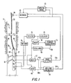
- FIG. 1 there is shown an embodiment of the type of apparatus 10, for investigating subsurface formations 31 traversed by a borehole 32, which includes the improvements of the invention.
- the borehole 32 is typically filled with a drilling fluid or mud which contains finally divided solids in suspension.
- the fluid pressure in the formations traversed by the borehole is less than the hydrostatic pressure of the column of mud in the borehole, so that the mud and mud filtrate flow somewhat into the formations.
- the formations tend to screen the small particles suspended in the mud so that a mudcake 40 is formed on the walls of the borehole.
- the investigating apparatus or logging device 30 is suspended in the borehole 32 on an armored cable 33, the length of which substantially determines the relative depth of the device 30.
- the cable length is controlled by suitable means at the surface such as a drum and winch mechanism (not shown).
- the logging device 30 includes an elongated cylindrical sonde 34, the interior portion of which has a fluid-tight housing containing the bulk of the downhole electronics.
- a pad 37 which contains, inter alia, vertically spaced transmitting antennas T1 and T2, and vertically spaced receiving antennas R1 and R2 between the transmitting antennas.
- a backup arm 38 which may be hydraulically controlled to maintain the pad 37 in contact with the borehole wall.
- the backup arm 38 can also be used to provide a caliper reading.
- Electronic signals indicative of the information obtained by the logging device are transmitted through the cable 33 to a computing module 85 and a recorder 95, typically located at the surface of the earth.
- a computing module 85 and a recorder 95 typically located at the surface of the earth.
- An oscillator 45 provides output energy which, in the present invention, is preferably greater than 100 MHz, and, in the example hereof is 1100 MHz.
- the output of oscillator 45 is coupled through isolator 46 and switching circuit 71 to the transmitting antennas T1 and T2, respectively.
- the transmitters T1 and T2 can be alternately enabled to implement "borehole compensated" operation. In this regard see, for example, US-A-3 849 721.
- the roles of the receivers are also switched as part of the borehole compensation scheme and to compensate for amplifier drift and other processing instabilities.
- This type stitching can also be utilized in the context of the present invention.
- the improvements of the present invention are not, per se, directed to borehole compensation or the referenced switching or processing, so for ease of explanation the receivers R1 and R2 will be respectively considered as the near and far receivers during transmission from transmitter T1, and the case of transmission from transmitter T2 will not be described in detail.
- Electromagnetic energy is transmitted from transmitter T1 into the surrounding formations.
- Energy received at receiving antennas R1 and R2 is respectively coupled to input terminals of mixers 47 and 48.
- the signals which arrive from R1 and R2 are out of phase with each other by an amount which depends upon properties of the surrounding formations and have an amplitude ratio which also depends upon properties of the surrounding formations.
- Secondary input terminals of the mixers are supplied with energy at a frequency that is separated from the transmitter frequency by some relatively low frequency which is typically in the kilohertz frequency range.
- oscillator 49 supplies electromagnetic energy to mixers 47 and 48 at a frequency that is, for example, 10 KHz. above the transmitter frequency.
- the output signals 47A and 48A of the mixers 47 and 48 therefore contain the difference frequency of 10 KHz.
- the signals 47A and 48A maintain the phase and amplitude relationships of the signals from R1 and R2, but the task of phase detection is greatly facilitated at the lower frequency of the mixed signals.
- the oscillator outputs are sampled and fed to a mixer 50.
- the output of the mixer is received by a frequency stabilization circuit 51 which detects drifts from the 10 KHz. standard and generates a correction signal 51A which controls oscillator 49 in the manner of a conventional "phase-locked loop".
- the signals 47A and 48A are applied to a phase detector circuit 53 and to an amplitude comparator 54.
- the output of the phase detector 53 is a signal level which is proportional to the phase difference between the signals received at R2 and R1.
- the output of amplitude comparator 54 is a signal level which is proportional to the relative amplitude of the signal received at R2 with respect to the signal received at R1. Suitable types of phase and amplitude comparator circuits are known in the art. (Also, see the above-referenced US-A-3,944,910.)
- the outputs of the phase detector circuit 53 and the amplitude comparison circuit 54 are transmitted to the surface over the conductor pair 53A and 54A which in actuality pass through the armored cable 33.
- These signals may be, for example, D.C. levels which are stepped-up by amplification before transmission to the surface, or may be converted to digital form downhole before transmission to the surface.
- the signals on lines 53A and 54A are recorded by a recorder 95 that is conventionally driven as a function of borehole depth by mechanical coupling to a rotating wheel 96.
- the wheel 96 is coupled to the cable 33 and rotates in synchronism therewith so as to move as a function of borehole depth.
- these signals may also typically be coupled to a computing module 85.
- the computing module may include processing means for determining the dielectric constant and/or the conductivity of the invaded zone of the surrounding formations.
- the recording means may alternately include processing means for determining other parameters of the surrounding formations, as is known in the art.
- the present invention is directed to improvements in the structure of the logging device, and is not limited by the manner in which detected signals are processed.
- absolute measurements of phase and/or amplitude relative to the transmitter may be taken and utilized, if desired. These measurements can also be useful in a determination of mudcake resistivity and thickness.
- FIG.s 2 and 3 illustrate a form of the pad 37 in accordance with an embodiment of the invention.
- the pad is mounted in an opening in the sonde 34, and includes a metal base 210 in which the antennas T1, R1, R2, and T2 are formed.
- the base 210 comprises four metal sections secured to a frame 220 under the base.
- the frame 220 includes openings through which the coaxial lines pass to and from the sonde 34 where they are coupled to the circuitry such as is represented in FIG. 1.
- Metal end ploughs 231 and 232 are utilized to cut through the mudcake and facilitate movement of the pad along the borehole wall.
- the slot antennas utilized herein as the transmitting and receiving antennas are shown in greater detail in FIG.s 4-6.
- the slot antennas hereof are each formed by a slot in the metal base 210 and are filled with a dielectric material 215 having a dielectric constant of, for example, about 5.
- the slots have a length and a width that are both less than a half wavelength and a depth that is less than a quarter wavelength at the operating frequency in the dielectric material that fills the slot, so there will be no standing waves in the slot.
- the length and width will both be less than one-quarter wavelength, and the depth less than one-eighth wavelength at the operating frequency in the dielectric material.
- a conductive probe rod, or wire, 250 extends across the slot in a direction parallel to the borehole axis, and is shorted, at one end, to the slot wall in base 210.
- the other end of probe 250 passes through an insulating ceramic pressure seal 260, and is coupled to one end of a tuning element 300 which, in the present embodiment, is represented by a capacitor.
- the seal 260 serves to isolate the tuning element frown the slot environment, to prevent any incursion of water or other substance, or from mechanical pertubations which might change or degrade the characteristics of the tuning element.
- the slot antenna hereof acts as a magnetic dipole oriented parallel to the plane of the pad member.
- the tuning element 300 is substantially capacitive, although it will be understood that some inductive tuning can be employed to tune parasitic capacitance.
- the tuning element 300 may be a lumped capacitor, shunt stub or other suitable element.
- the other end of capacitor 300 is coupled to the center conductor of a coaxial line, the outer conductor of which is coincident with, or coupled to, the metal base 210.
- Each coaxial line is coupled to a connector, as represented in FIG. 3, for connection to the appropriate transmitter or receiver line.
- Magnetic fields are parallel to the surface of a good conductor, while electric fields are normal to the surface.
- a small hole in the surface of a conductor allows some of the magnetic and electric fields to penetrate into the hole. If the dimensions of the hole are small compared to a wavelength, it has been shown that the hole can be modelled as the sum of a magnetic dipole parallel to the plane of the conductor and an electric dipole perpendicular to the plane of the conductor (see, for example, H. A. Bethe, "Theory of Diffraction of Small Holes", Phys. Rev. vol. 66, pp. 163-182, 1944).
- the antennas hereof make use of the magnetic dipole component of the hole, but not the electric dipole component.
- the antenna can be modified as shown in FIG.s 8 and 9.
- the probe is rendered less sensitive to the electric field by enclosing all but its center in a shield.
- the shield consists of two outer cylindrical conductors that are shorted to the slot walls. The gap between the cylinders is placed exactly in the middle of the slot, which renders this design highly symmetric. Most of the electric lines that penetrate into the slot terminate on the shield and do not excite the probe itself. Since the shield is opened in the center, the electromotive force induced by the magnetic field still excites the probe.
- the magnetic field at the pad surface at a receiving antenna due to the transmitting antenna can be expressed as where k * is the formation complex propagation constant and r is the distance between the two antennas.
- the received signal at the coaxial line, V will be proportional to H y .
- the ratio of the near receiver signal to the far receiver signal is where G is magnitude of the signal ratio in db, and ⁇ is the phase of the signal ratio in radians.
- G is magnitude of the signal ratio in db
- ⁇ is the phase of the signal ratio in radians.
- k * can be determined using relationship (3).
- the natural log of the last bracketed term of relationship (3) is close to zero, k * can be solved for, as a first approximation, without such term.
- the k * obtained in this way can then be used on the righthand side of the complete expression (3) to obtain a better value of k * , and the procedure will converge quickly to a solution value of k * .
- the dielectric constant ⁇ ' and conductivity a can then be obtained using where k' and k'' are respectively the real and imaginary parts of k * , k0 is the free space propagation, and ⁇ the angular frequency of operation.
- Alternatives to the iterative numerical solution set forth would be a table look-up technique or a curve matching technique, both well known in the art.
- a further possible approach is to provide a special purpose analog or digital processor which provides output functions that represent the relationships set forth. It will also be recognized that by using the described logging device in a suitably large test pit borehole, stored values can be obtained empirically.
Landscapes
- Life Sciences & Earth Sciences (AREA)
- Physics & Mathematics (AREA)
- General Physics & Mathematics (AREA)
- Geophysics (AREA)
- Environmental & Geological Engineering (AREA)
- Geology (AREA)
- Remote Sensing (AREA)
- General Life Sciences & Earth Sciences (AREA)
- Electromagnetism (AREA)
- Engineering & Computer Science (AREA)
- Geophysics And Detection Of Objects (AREA)
- Variable-Direction Aerials And Aerial Arrays (AREA)
- Support Of Aerials (AREA)
- Analysing Materials By The Use Of Radiation (AREA)
- Cash Registers Or Receiving Machines (AREA)
- Devices That Are Associated With Refrigeration Equipment (AREA)
Claims (10)
- Gerät zur Untersuchung von ein Bohrloch umgebenden Formationen, umfassend:
ein Loggerät (30), das durch das Bohrloch beweglich ist,
ein an dem Loggerät montiertes Glied (37), ausgebildet für den Kontakt mit der Bohrlochwandung,
eine Sendeantenne (T1, T2), die auf der die Wandung kontaktierenden Seite des Gliedes (37) montiert ist,
ein Paar beabstandeter Empfangsantennen (R1, R2), montiert auf der wandungskontaktierenden Seite des Gliedes (37) im Abstand von der Sendeantenne (T1, T2),
Mittel zum Erregen der Sendeantenne (T1, T2) zum Aussenden elektromagnetischer Energie in die Formationen, und
Mittel für das Erzeugen eines Ausgangs an jeder der Empfangsantennen (R1, R2), der repräsentativ ist für elektromagnetische Energie, die aus den Formationen empfangen wird,
wobei jede der Antennen eine leitende Basis (210) umfaßt, welche mit einem Schlitz versehen ist, der sich in Richtung der Bohrlochwandung öffnet, welcher Schlitz im wesentlichen mit einem dielektrischen Material (215) gefüllt ist, und wobei sich eine leitende Sonde (250) in dem Schlitz befindet,
dadurch gekennzeichnet, daß jede der Antennen ein Abstimmelement (300), getrennt von dem Schlitz und der Sonde (250), umfaßt, welches Abstimmelement (300) an die Sonde angekoppelt ist, daß die Sendeantenne (T1, T2) erregt wird durch Anlegen eines Signals an das Abstimmelement (300), relativ zu der Basis (210), und daß der Ausgang der Empfangsantenne (R1, R2) erzeugt wird durch Gewinnen eines Signals über dem Abstimmelement (300) relativ zu der Basis (210). - Vorrichtung nach Anspruch 1, bei der das Abstimmelement (300) ein kapazitives Abstimmelement ist.
- Vorrichtung nach Anspruch 1 oder 2, ferner umfassend Abdichtmittel (260), die das Abstimmelement von dem Schlitz trennen.
- Vorrichtung nach Anspruch 1, 2 oder 3, bei der die Länge und Breite des Schlitzes kleiner sind als eine halbe Wellenlänge bei der Betriebsfrequenz in dem dielektrischen Material (215) des Schlitzes, und bei der die Tiefe des Schlitzes kleiner ist als eine viertel Wellenlänge bei der Betriebsfrequenz in dem dielektrischen Material des Schlitzes.
- Vorrichtung nach Anspruch 1, 2 oder 3, bei der die Länge und Breite des Schlitzes kleiner sind als eine viertel Wellenlänge bei der Betriebsfrequenz in dem dielektrischen Material (215) des Schlitzes, und bei der die Tiefe des Schlitzes kleiner ist als ein Achtel einer Wellenlänge bei der Betriebsfrequenz in dem dielektrischen Material des Schlitzes.
- Vorrichtung nach einem der Ansprüche 1 bis 5, bei der die leitende Sonde (250) in jeder der Antennen sich über den Schlitz in einer Richtung parallel zur Bohrlochachse erstreckt und an einem Ende mit einer Wandung des Schlitzes kurzgeschlossen ist.
- Vorrichtung nach Anspruch 6, ferner umfassend leitende Abschirmmittel (Fig. 8 und 9), angekoppelt an die Metallbasis (210) und einen Abschnitt der Sonde umgebend, die den Schlitz kreuzt.
- Vorrichtung nach Anspruch 7, bei der ein zentraler Abschnitt der Sonde (250) in dem Schlitz unabgeschirmt ist, und die Abschirmmittel beabstandete rohrförmige Leiter (Fig. 8 und 9) umfassen, angekoppelt an die Metallbasis und den Rest der Sonde in dem Schlitz umgebend.
- Vorrichtung nach einem der Ansprüche 1 bis 8, ferner umfassend auf die Ausgänge der Empfangsantennen ansprechende Mittel zum Gewinnen der relativen Amplitude (54) und Phase (53) der Ausgänge der Empfangsantennen sowie Mittel für die Bestimmung der Dielektrizitätskonstante (85) der Formationen als Funktion der Amplitude und Phase.
- Vorrichtung für die Untersuchung von ein Bohrloch umgebenden Formationen, umfassend:
ein Loggerät (30), das durch das Bohrloch bewegbar ist,
ein auf dem Loggerät montiertes Glied (37), ausgebildet für den Kontakt mit der Bohrlochwandung,
eine Sendeantenne (T1, T2), montiert in der wandungskontaktierenden Seite des Gliedes (37),
ein Paar von beabstandeten Empfangsantennen (R1, R2), montiert in der wandungskontaktierenden Seite des Gliedes (37) und im Abstand von der Sendeantenne (T1, T2),
wobei jede der Antennen umfaßt: Eine leitende Basis (210) mit einem Schlitz, der sich in Richtung der Bohrlochwandung öffnet, welcher Schlitz im wesentlichen mit einem dielektrischen Material (215) gefüllt ist, sowie eine leitende Sonde (250) in dem Schlitz,
Mittel für das Erregen der Sendeantenne (T1, T2) zum Aussenden elektromagnetischer Energie in die Formationen durch Anlegen eines Signals an die Sonde relativ zu der Basis, und
Mittel für das Erzeugen eines Ausgangs an jeder der Empfangsantennen (R1, R2), repräsentativ für elektromagnetische Energie, die aus den Formationen empfangen wird durch Gewinnen eines Signals über der Sonde relativ zu der Basis,
dadurch gekennzeichnet, daß die Länge und Breite des Schlitzes kleiner sind als eine halbe Wellenlänge bei der Betriebsfrequenz in dem dielektrischen Material (215) des Schlitzes, und daß die Tiefe des Schlitzes kleiner ist als eine viertel Wellenlänge bei der Betriebsfrequenz in dem dielektrischen Material (215) des Schlitzes.
Priority Applications (1)
| Application Number | Priority Date | Filing Date | Title |
|---|---|---|---|
| AT85402444T ATE66304T1 (de) | 1984-12-28 | 1985-12-10 | Geraet zur elektromagnetischen untersuchung in einem bohrloch mit schlitzantennen. |
Applications Claiming Priority (2)
| Application Number | Priority Date | Filing Date | Title |
|---|---|---|---|
| US06/687,071 US4689572A (en) | 1984-12-28 | 1984-12-28 | Electromagnetic logging apparatus with slot antennas |
| US687071 | 1984-12-28 |
Publications (3)
| Publication Number | Publication Date |
|---|---|
| EP0186570A2 EP0186570A2 (de) | 1986-07-02 |
| EP0186570A3 EP0186570A3 (en) | 1988-08-10 |
| EP0186570B1 true EP0186570B1 (de) | 1991-08-14 |
Family
ID=24758928
Family Applications (1)
| Application Number | Title | Priority Date | Filing Date |
|---|---|---|---|
| EP85402444A Expired - Lifetime EP0186570B1 (de) | 1984-12-28 | 1985-12-10 | Gerät zur elektromagnetischen Untersuchung in einem Bohrloch mit Schlitzantennen |
Country Status (9)
| Country | Link |
|---|---|
| US (1) | US4689572A (de) |
| EP (1) | EP0186570B1 (de) |
| CN (1) | CN1011723B (de) |
| AT (1) | ATE66304T1 (de) |
| DE (1) | DE3583797D1 (de) |
| ES (1) | ES8705128A1 (de) |
| MX (1) | MX158468A (de) |
| NO (1) | NO854831L (de) |
| OA (1) | OA08153A (de) |
Cited By (1)
| Publication number | Priority date | Publication date | Assignee | Title |
|---|---|---|---|---|
| US9556726B2 (en) | 2014-05-16 | 2017-01-31 | Baker Hughes Incorporated | Use of a fractal antenna in array dielectric logging |
Families Citing this family (25)
| Publication number | Priority date | Publication date | Assignee | Title |
|---|---|---|---|---|
| US4857852A (en) * | 1986-06-20 | 1989-08-15 | Schlumberger Technology Corp. | Induction well logging apparatus with transformer coupled phase sensitive detector |
| US5132903A (en) * | 1990-06-19 | 1992-07-21 | Halliburton Logging Services, Inc. | Dielectric measuring apparatus for determining oil and water mixtures in a well borehole |
| US5210495A (en) * | 1991-05-28 | 1993-05-11 | Schlumberger Technology Corp. | Electromagnetic logging method and apparatus with scanned magnetic dipole direction |
| AU654346B2 (en) * | 1991-05-28 | 1994-11-03 | Schlumberger Technology B.V. | Slot antenna having two nonparallel elements |
| US5345179A (en) * | 1992-03-09 | 1994-09-06 | Schlumberger Technology Corporation | Logging earth formations with electromagnetic energy to determine conductivity and permittivity |
| US5434507A (en) * | 1992-05-27 | 1995-07-18 | Schlumberger Technology Corporation | Method and apparatus for electromagnetic logging with two dimensional antenna array |
| US5302781A (en) * | 1993-02-05 | 1994-04-12 | Schlumberger Technology Corporation | Sidewall contact temperature tool including knife edge sensors for cutting through mudcake and measuring formation temperature |
| US5453693A (en) * | 1993-10-01 | 1995-09-26 | Halliburton Company | Logging system for measuring dielectric properties of fluids in a cased well using multiple mini-wave guides |
| US5530358A (en) * | 1994-01-25 | 1996-06-25 | Baker Hughes, Incorporated | Method and apparatus for measurement-while-drilling utilizing improved antennas |
| DE19547956A1 (de) * | 1995-12-21 | 1997-06-26 | Klaus Ebinger | Elektromagnetisches Suchverfahren und Sondenanordnung zur Ortung von unter der Oberfläche liegenden Objekten |
| US6566881B2 (en) * | 1999-12-01 | 2003-05-20 | Schlumberger Technology Corporation | Shielding method and apparatus using transverse slots |
| US7242194B2 (en) * | 2000-04-07 | 2007-07-10 | Schlumberger Technology Corporation | Formation imaging while drilling in non-conductive fluids |
| US6788263B2 (en) * | 2002-09-30 | 2004-09-07 | Schlumberger Technology Corporation | Replaceable antennas for subsurface monitoring apparatus |
| US7436183B2 (en) * | 2002-09-30 | 2008-10-14 | Schlumberger Technology Corporation | Replaceable antennas for wellbore apparatus |
| US7284605B2 (en) * | 2004-09-28 | 2007-10-23 | Schlumberger Technology Corporation | Apparatus and methods for reducing stand-off effects of a downhole tool |
| US7669668B2 (en) * | 2004-12-01 | 2010-03-02 | Schlumberger Technology Corporation | System, apparatus, and method of conducting measurements of a borehole |
| US7348781B2 (en) * | 2004-12-31 | 2008-03-25 | Schlumberger Technology Corporation | Apparatus for electromagnetic logging of a formation |
| US8022983B2 (en) * | 2005-04-29 | 2011-09-20 | Schlumberger Technology Corporation | Borehole imaging system for conductive and resistive drilling fluids |
| US7477162B2 (en) * | 2005-10-11 | 2009-01-13 | Schlumberger Technology Corporation | Wireless electromagnetic telemetry system and method for bottomhole assembly |
| US9035657B2 (en) * | 2009-04-10 | 2015-05-19 | Schlumberger Technology Corporation | Electromagnetic logging between a cased borehole and surface |
| US8638103B2 (en) * | 2009-04-10 | 2014-01-28 | Schlumberger Technology Corporation | Electromagnetic logging between borehole and surface |
| US9377555B2 (en) | 2010-12-23 | 2016-06-28 | China Petroleum & Chemical Corporation | Apparatus and method for well logging and data processing device |
| GB2536532A (en) * | 2013-09-03 | 2016-09-21 | Halliburton Energy Services Inc | Deep sensing systems |
| US10317558B2 (en) * | 2017-03-14 | 2019-06-11 | Saudi Arabian Oil Company | EMU impulse antenna |
| JP2021504685A (ja) * | 2017-11-22 | 2021-02-15 | サウジ アラビアン オイル カンパニー | 巨大誘電体およびフェライト材料を用いた低周波電波のためのemuインパルスアンテナ |
Family Cites Families (15)
| Publication number | Priority date | Publication date | Assignee | Title |
|---|---|---|---|---|
| US2945232A (en) * | 1949-03-07 | 1960-07-12 | Alford Andrew | Antenna structure |
| US2947987A (en) * | 1958-05-05 | 1960-08-02 | Itt | Antenna decoupling arrangement |
| US3665480A (en) * | 1969-01-23 | 1972-05-23 | Raytheon Co | Annular slot antenna with stripline feed |
| US3586206A (en) * | 1969-04-29 | 1971-06-22 | Bess P Gilmore | Container for a stack of articles |
| CA1040261A (en) * | 1973-08-23 | 1978-10-10 | Schlumberger Canada Limited | Method and apparatus for investigating earth formations |
| IE39998B1 (en) * | 1973-08-23 | 1979-02-14 | Schlumberger Inland Service | Method and apparatus for investigating earth formations |
| US3849721A (en) * | 1973-08-23 | 1974-11-19 | Schlumberger Technology Corp | Microwave logging apparatus having dual processing channels |
| US3944910A (en) * | 1973-08-23 | 1976-03-16 | Schlumberger Technology Corporation | Method and apparatus utilizing microwave electromagnetic energy for investigating earth formations |
| US4239010A (en) * | 1979-06-29 | 1980-12-16 | Dickey-John Corporation | Microwave seed sensor for field seed planter |
| US4511842A (en) * | 1981-10-13 | 1985-04-16 | Schlumberger Technology Corporation | Electromagnetic logging device and method with dielectric guiding layer |
| DE3208789A1 (de) * | 1982-03-11 | 1983-09-22 | Standard Elektrik Lorenz Ag, 7000 Stuttgart | Antenne mit mindestens einem dipol |
| AU2907484A (en) * | 1983-06-27 | 1985-01-03 | N L Industries Inc. | Drill stem logging system |
| US4578645A (en) * | 1984-02-01 | 1986-03-25 | Mobil Oil Corporation | Borehole logging tool utilizing electromagnetic energy in the determination of dip of subsurface formations surrounding a borehole |
| US4581584A (en) * | 1984-02-03 | 1986-04-08 | Mobil Oil Corporation | Microwave electromagnetic borehole dipmeter |
| US4590480A (en) * | 1984-08-31 | 1986-05-20 | Rca Corporation | Broadcast antenna which radiates horizontal polarization towards distant locations and circular polarization towards nearby locations |
-
1984
- 1984-12-28 US US06/687,071 patent/US4689572A/en not_active Expired - Lifetime
-
1985
- 1985-11-19 MX MX656A patent/MX158468A/es unknown
- 1985-11-23 CN CN85108416A patent/CN1011723B/zh not_active Expired
- 1985-12-02 NO NO854831A patent/NO854831L/no unknown
- 1985-12-10 DE DE8585402444T patent/DE3583797D1/de not_active Expired - Lifetime
- 1985-12-10 EP EP85402444A patent/EP0186570B1/de not_active Expired - Lifetime
- 1985-12-10 AT AT85402444T patent/ATE66304T1/de active
- 1985-12-27 ES ES550461A patent/ES8705128A1/es not_active Expired
- 1985-12-27 OA OA58754A patent/OA08153A/xx unknown
Cited By (1)
| Publication number | Priority date | Publication date | Assignee | Title |
|---|---|---|---|---|
| US9556726B2 (en) | 2014-05-16 | 2017-01-31 | Baker Hughes Incorporated | Use of a fractal antenna in array dielectric logging |
Also Published As
| Publication number | Publication date |
|---|---|
| OA08153A (en) | 1987-03-31 |
| ATE66304T1 (de) | 1991-08-15 |
| NO854831L (no) | 1986-06-30 |
| ES550461A0 (es) | 1987-04-16 |
| CN85108416A (zh) | 1986-07-09 |
| CN1011723B (zh) | 1991-02-20 |
| ES8705128A1 (es) | 1987-04-16 |
| EP0186570A3 (en) | 1988-08-10 |
| US4689572A (en) | 1987-08-25 |
| DE3583797D1 (de) | 1991-09-19 |
| EP0186570A2 (de) | 1986-07-02 |
| MX158468A (es) | 1989-02-03 |
Similar Documents
| Publication | Publication Date | Title |
|---|---|---|
| EP0187583B1 (de) | Gerät zur elektromagnetischen Untersuchung in einem Bohrloch mit Knopfantennen | |
| EP0186570B1 (de) | Gerät zur elektromagnetischen Untersuchung in einem Bohrloch mit Schlitzantennen | |
| US4704581A (en) | Electromagnetic logging apparatus using vertical magnetic dipole slot antennas | |
| US4511842A (en) | Electromagnetic logging device and method with dielectric guiding layer | |
| CA1037118A (en) | Method and apparatus for investigating earth formations | |
| US5402068A (en) | Method and apparatus for logging-while-drilling with improved performance through cancellation of systemic errors through combination of signals, utilization of dedicated transmitter drivers, and utilization of selected reference signals | |
| US5345179A (en) | Logging earth formations with electromagnetic energy to determine conductivity and permittivity | |
| US4052662A (en) | Method and apparatus for investigating earth formations utilizing microwave electromagnetic energy | |
| US5210495A (en) | Electromagnetic logging method and apparatus with scanned magnetic dipole direction | |
| US4536714A (en) | Shields for antennas of borehole logging devices | |
| US4968940A (en) | Well logging apparatus and method using two spaced apart transmitters with two receivers located between the transmitters | |
| EP0105801B1 (de) | Verwendung der transversalen magnetischen Komponente in einem Bohrlochmessgerät | |
| US4949045A (en) | Well logging apparatus having a cylindrical housing with antennas formed in recesses and covered with a waterproof rubber layer | |
| US4845433A (en) | Apparatus for microinductive investigation of earth formations | |
| USRE32913E (en) | Shields for antennas of borehole logging devices | |
| US4780678A (en) | Apparatus for microinductive investigation of earth formations | |
| US4300098A (en) | Microwave electromagnetic logging with mudcake correction | |
| US4712070A (en) | Apparatus for microinductive investigation of earth formations | |
| US4077003A (en) | Microwave method and apparatus utilizing dielectric loss factor measurements for determination of adsorbed fluid in subsurface formations surrounding a borehole | |
| US4739272A (en) | Apparatus for microinductive investigation of earth formations with improved electroquasistatic shielding | |
| US4158165A (en) | Apparatus and method for determining subsurface formation properties | |
| US4678997A (en) | Method and apparatus for dielectric well logging of subsurface earth formations with a lumped constant antenna | |
| CA1078015A (en) | Method and apparatus for determination for absorbed fluid in subsurface formations | |
| US4338567A (en) | Apparatus and method for determination of bound water in subsurface formations | |
| US4156177A (en) | Apparatus and method for determination of free fluid in subsurface formations |
Legal Events
| Date | Code | Title | Description |
|---|---|---|---|
| PUAI | Public reference made under article 153(3) epc to a published international application that has entered the european phase |
Free format text: ORIGINAL CODE: 0009012 |
|
| AK | Designated contracting states |
Kind code of ref document: A2 Designated state(s): AT DE FR GB IT NL |
|
| PUAL | Search report despatched |
Free format text: ORIGINAL CODE: 0009013 |
|
| RHK1 | Main classification (correction) |
Ipc: G01V 3/30 |
|
| AK | Designated contracting states |
Kind code of ref document: A3 Designated state(s): AT DE FR GB IT NL |
|
| 17P | Request for examination filed |
Effective date: 19890116 |
|
| 17Q | First examination report despatched |
Effective date: 19900402 |
|
| GRAA | (expected) grant |
Free format text: ORIGINAL CODE: 0009210 |
|
| AK | Designated contracting states |
Kind code of ref document: B1 Designated state(s): AT DE FR GB IT NL |
|
| PG25 | Lapsed in a contracting state [announced via postgrant information from national office to epo] |
Ref country code: NL Effective date: 19910814 Ref country code: AT Effective date: 19910814 Ref country code: IT Free format text: LAPSE BECAUSE OF FAILURE TO SUBMIT A TRANSLATION OF THE DESCRIPTION OR TO PAY THE FEE WITHIN THE PRESCRIBED TIME-LIMIT;WARNING: LAPSES OF ITALIAN PATENTS WITH EFFECTIVE DATE BEFORE 2007 MAY HAVE OCCURRED AT ANY TIME BEFORE 2007. THE CORRECT EFFECTIVE DATE MAY BE DIFFERENT FROM THE ONE RECORDED. Effective date: 19910814 |
|
| REF | Corresponds to: |
Ref document number: 66304 Country of ref document: AT Date of ref document: 19910815 Kind code of ref document: T |
|
| REF | Corresponds to: |
Ref document number: 3583797 Country of ref document: DE Date of ref document: 19910919 |
|
| ET | Fr: translation filed | ||
| NLV1 | Nl: lapsed or annulled due to failure to fulfill the requirements of art. 29p and 29m of the patents act | ||
| PLBE | No opposition filed within time limit |
Free format text: ORIGINAL CODE: 0009261 |
|
| STAA | Information on the status of an ep patent application or granted ep patent |
Free format text: STATUS: NO OPPOSITION FILED WITHIN TIME LIMIT |
|
| 26N | No opposition filed | ||
| PGFP | Annual fee paid to national office [announced via postgrant information from national office to epo] |
Ref country code: DE Payment date: 19940127 Year of fee payment: 9 |
|
| PG25 | Lapsed in a contracting state [announced via postgrant information from national office to epo] |
Ref country code: DE Effective date: 19950901 |
|
| REG | Reference to a national code |
Ref country code: GB Ref legal event code: IF02 |
|
| PGFP | Annual fee paid to national office [announced via postgrant information from national office to epo] |
Ref country code: GB Payment date: 20021204 Year of fee payment: 18 |
|
| PGFP | Annual fee paid to national office [announced via postgrant information from national office to epo] |
Ref country code: FR Payment date: 20021210 Year of fee payment: 18 |
|
| PG25 | Lapsed in a contracting state [announced via postgrant information from national office to epo] |
Ref country code: GB Free format text: LAPSE BECAUSE OF NON-PAYMENT OF DUE FEES Effective date: 20031210 |
|
| GBPC | Gb: european patent ceased through non-payment of renewal fee |
Effective date: 20031210 |
|
| PG25 | Lapsed in a contracting state [announced via postgrant information from national office to epo] |
Ref country code: FR Free format text: LAPSE BECAUSE OF NON-PAYMENT OF DUE FEES Effective date: 20040831 |
|
| REG | Reference to a national code |
Ref country code: FR Ref legal event code: ST |