EP0186529A1 - Frame for supporting a sheet of glass during tempering - Google Patents
Frame for supporting a sheet of glass during tempering Download PDFInfo
- Publication number
- EP0186529A1 EP0186529A1 EP85402080A EP85402080A EP0186529A1 EP 0186529 A1 EP0186529 A1 EP 0186529A1 EP 85402080 A EP85402080 A EP 85402080A EP 85402080 A EP85402080 A EP 85402080A EP 0186529 A1 EP0186529 A1 EP 0186529A1
- Authority
- EP
- European Patent Office
- Prior art keywords
- frame
- glass sheet
- frame according
- channels
- spans
- Prior art date
- Legal status (The legal status is an assumption and is not a legal conclusion. Google has not performed a legal analysis and makes no representation as to the accuracy of the status listed.)
- Granted
Links
- 239000011521 glass Substances 0.000 title claims abstract description 50
- 238000005496 tempering Methods 0.000 title claims abstract description 12
- 238000007664 blowing Methods 0.000 claims abstract description 12
- 239000000463 material Substances 0.000 claims description 7
- 239000002184 metal Substances 0.000 claims description 3
- 229910052751 metal Inorganic materials 0.000 claims description 3
- 230000015572 biosynthetic process Effects 0.000 claims description 2
- 238000005524 ceramic coating Methods 0.000 claims description 2
- 238000007599 discharging Methods 0.000 claims 1
- 239000007789 gas Substances 0.000 abstract description 6
- 238000005452 bending Methods 0.000 description 11
- 238000001816 cooling Methods 0.000 description 8
- 238000000034 method Methods 0.000 description 5
- 230000003287 optical effect Effects 0.000 description 5
- 238000010791 quenching Methods 0.000 description 4
- 230000000171 quenching effect Effects 0.000 description 4
- 239000000919 ceramic Substances 0.000 description 3
- 230000007547 defect Effects 0.000 description 3
- 229910000831 Steel Inorganic materials 0.000 description 2
- 238000010276 construction Methods 0.000 description 2
- 230000000694 effects Effects 0.000 description 2
- 238000004519 manufacturing process Methods 0.000 description 2
- 238000003801 milling Methods 0.000 description 2
- 239000010959 steel Substances 0.000 description 2
- 229910000851 Alloy steel Inorganic materials 0.000 description 1
- 229910000640 Fe alloy Inorganic materials 0.000 description 1
- 230000002411 adverse Effects 0.000 description 1
- 229910010293 ceramic material Inorganic materials 0.000 description 1
- 150000001875 compounds Chemical class 0.000 description 1
- 239000004020 conductor Substances 0.000 description 1
- 239000004035 construction material Substances 0.000 description 1
- 238000009826 distribution Methods 0.000 description 1
- 230000002349 favourable effect Effects 0.000 description 1
- 239000005357 flat glass Substances 0.000 description 1
- 238000010438 heat treatment Methods 0.000 description 1
- 238000009434 installation Methods 0.000 description 1
- 239000011229 interlayer Substances 0.000 description 1
- 229910000765 intermetallic Inorganic materials 0.000 description 1
- 150000002736 metal compounds Chemical class 0.000 description 1
- 238000005507 spraying Methods 0.000 description 1
- 239000005341 toughened glass Substances 0.000 description 1
Images

Classifications
-
- C—CHEMISTRY; METALLURGY
- C03—GLASS; MINERAL OR SLAG WOOL
- C03B—MANUFACTURE, SHAPING, OR SUPPLEMENTARY PROCESSES
- C03B27/00—Tempering or quenching glass products
- C03B27/04—Tempering or quenching glass products using gas
- C03B27/0404—Nozzles, blow heads, blowing units or their arrangements, specially adapted for flat or bent glass sheets
-
- C—CHEMISTRY; METALLURGY
- C03—GLASS; MINERAL OR SLAG WOOL
- C03B—MANUFACTURE, SHAPING, OR SUPPLEMENTARY PROCESSES
- C03B27/00—Tempering or quenching glass products
- C03B27/04—Tempering or quenching glass products using gas
- C03B27/044—Tempering or quenching glass products using gas for flat or bent glass sheets being in a horizontal position
- C03B27/0442—Tempering or quenching glass products using gas for flat or bent glass sheets being in a horizontal position for bent glass sheets
-
- C—CHEMISTRY; METALLURGY
- C03—GLASS; MINERAL OR SLAG WOOL
- C03B—MANUFACTURE, SHAPING, OR SUPPLEMENTARY PROCESSES
- C03B35/00—Transporting of glass products during their manufacture, e.g. hot glass lenses, prisms
- C03B35/14—Transporting hot glass sheets or ribbons, e.g. by heat-resistant conveyor belts or bands
- C03B35/20—Transporting hot glass sheets or ribbons, e.g. by heat-resistant conveyor belts or bands by gripping tongs or supporting frames
- C03B35/202—Transporting hot glass sheets or ribbons, e.g. by heat-resistant conveyor belts or bands by gripping tongs or supporting frames by supporting frames
-
- C—CHEMISTRY; METALLURGY
- C03—GLASS; MINERAL OR SLAG WOOL
- C03B—MANUFACTURE, SHAPING, OR SUPPLEMENTARY PROCESSES
- C03B40/00—Preventing adhesion between glass and glass or between glass and the means used to shape it, hold it or support it
- C03B40/005—Fabrics, felts or loose covers
Definitions
- the invention relates to a support frame for a glass sheet heated to its tempering or deformation temperature and in a horizontal position during the tempering blowing.
- the frame has a shape adapted to the contour and shape of the glass sheet which rests on spans, arranged on the upper face of the frame and between which are formed channels for evacuation of the blowing air sent to the face. bottom of the glass sheet.
- the frames are formed of metal dishes, arranged on edge and provided on their supporting surface with grooves forming evacuation channels.
- the frames are formed from horizontally arranged dishes, the flat surfaces of which correspond to the shape of the glass sheet and are provided on their surface, directed inwards with projecting fingers in horizontal position on which the glass sheet rests.
- the discharge channels, formed between the edge of the glass sheet and the frame, must have a sufficient cross section to ensure perfect quenching of the entire glass sheet, even on its edges.
- the spacing between the spans must not be very great because then the installation on different points of the glass sheet, being at its deformation temperature, leads to an annoying deformation of the marginal areas of the glass sheet .
- the known frames do not allow the two requirements for perfect quenching of the marginal areas of the sheet to be optimized. glass and the avoidance of annoying distortions. This is why in practice, the frame is often covered with a wire mesh with a fine mesh, so that the points of contact of the glass sheet with the frame are multiplied and equalized, and moreover a favorable influence is obtained. for the discharge of the supply air.
- covering the frame with a lattice leads to other drawbacks and in particular has an unfavorable influence on the dimensional stability of the support surface of the frame.
- the object of the invention is to provide a support frame where, on the one hand, undesirable deformations of the marginal zones of the glass sheet, caused by the bearing surfaces, are avoided, and which on the other hand leads to sufficient tempering and homogeneous of the glass sheet, even on its marginal areas.
- this is obtained by the fact that, at least in a chosen area of the frame, seen in the radial direction, there are provided several rows of spans and that the discharge channels located between the spans form a continuous network.
- the frame In one embodiment of the invention, satisfactory for many cases, only part of the frame is equipped, namely the part of the frame on which the edge of the glass sheet rests and where the highest requirements arise relatively the optical qualities of the glass sheet. It may for example be the upper edge of a retractable automotive glazing which, not being maintained by a frame, must be up to the edge free of deformation and optical defects. The lower edge of the retractable glazing, being invisible, poses with less severity these requirements relating to the optical quality and to the deformations of the glass sheet. In cases where the entire periphery of the glass sheet remains visible after the sheet has been put in place, it is recommended to use a frame according to the invention fully equipped.
- the invention is based on the discovery that the observed deformations, as well as the optical defects of the marginal areas of the glass sheet, are not only due to the state of the support surface of the frame - which is moreover adversely influenced. by the usual covering of the frame with an easily deformable wire mesh - but also more specifically under the conditions of air evacuation between the laying surface and the edges of the glass sheet.
- the invention can, for example, be carried out by placing the scopes one next to the other, in successive rows, one behind the other, viewed in the radial direction.
- the spans it has been found to be particularly advantageous for the spans to be arranged in respective rows offset from one another in successive rows, so that the formation of discharge channels flowing in the radial direction is avoided.
- a homogeneous cooling of the marginal zone of the glass sheet and one certainly avoids an alternating cooling effect which would result in an inherent way of a flow in radial direction, ie when the channels flowing between uninterrupted spans.
- Such a locally alternating cooling effect leads in particular to different degrees of quenching, which causes the optical defects observed in the marginal areas of the glass sheet and which, according to the invention, are on the contrary very greatly reduced or even completely avoided.
- the frame seen in the radial direction a certain number of spans are arranged laterally offset from each other, leaving between them channel-shaped intervals, crossing the frame obliquely and forming a continuous evacuation network.
- the spans must be arranged, according to a preferred development of the invention, so that these preferential directions do not develop in the radial direction but at an angle between 30 and 60 °, and preferably about 45 °.
- the spans must be arranged so as to represent obstacles to the discharge of the blowing gases so that the gas streams are forced to branch into a plurality of crossed channels and to cool the edge of the flue evenly if possible. the glass sheet.
- the surfaces must have a sufficient laying surface for the support of the glass sheet and be arranged at a spacing such that it allows good evacuation of the blowing gas. Good results are obtained in particular when the surface occupied by the intervals between the spans is equal to, or up to 4 times greater, the surface occupied by the surface for laying the spans.
- Frames according to the art are usually used for the transport of curved glass sheets, directly from the bending device to the tempering device which as such comprises two blowing boxes with nozzles or openings directed towards the glass sheet and in which is obtained a sudden cooling of the glass sheet for the purpose of tempering.
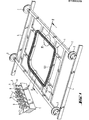
- the frame 1 is, for example, adequately fixed on a transport cart 2.
- the latter is provided with wheels 3 which allow it to be moved, on the rails 4 which connect the bending station to that of quenching.
- the transport carriage 2 is led from the bending station to the tempering station, and from there to the unloading station in which the toughened glass sheet is removed from the frame 1.
- the frame 1 can be used to take care of glass sheets that have been curved beforehand by means of a bending press or any other means. It can also serve itself as a bending form, the glass sheet being lifted with this frame 1 and pressed gives a bending surface of shape corresponding to that of frame 1, or even heated to its bending temperature, again flat, the glass sheet being dropped (in a horizontal position), on the frame 1 of an adequate height. This latter bending process is, like the previous ones, well known and usual.
- the frame 1 can also be used to transport the glass sheets 6 throughout their journey through the heating and bending furnaces and the tempering station which relates thereto.
- the frame according to the invention can be used independently of the bending process applied and can even be used for tempering of flat glass sheets.
- the frame 1 can be made in one piece or consist of several segments assembled in the form of a closed ring. It is a robust, relatively nassive construction in order to reduce, if not completely exclude, the danger of deformation of the frame due to thermal or mechanical stresses.
- the material used for the construction of the frame 1 must be suitable for precise work with the usual tools in order to obtain with high precision the desired shape of the support surface.
- this material must have a relatively low thermal conductivity, because difficulties may arise with materials which are good conductors of heat in the case where the sheet of glass, which is strongly heated, is placed on a frame, brought to a relatively low temperature. Ceramic materials are then suitable, which can be worked with machine tools, as well as iron alloys or special steels with low thermal conductivity and low coefficient of diffusivity such as refractory steel Fluginox N42 (registered trademark ).
- the frame 1 On the upper surface of the frame 1, in a regular and dense arrangement, is arranged a plurality of spans (8), directed vertically upwards and the upper surfaces of which jointly form the surface for laying the edge of the glass sheet. (6). In most cases it is sufficient for the glass sheet (6) to rest on the surfaces (8) only along a border, over a width A of approximately 10 to 15 mm.
- the width B of the bearing part of the frame 1, formed by all of the bearing surfaces 8 is, suitably a little greater than the width A covered by the glass sheet.
- the surfaces 8 have a height H of between 2 and 10 mm and in the intervals between the surfaces forms a network of channels through which the cooling air is directed, directed towards the lower surface of the glass sheet and coming from the blowing nozzles 1 of the lower box 12, as illustrated in particular in FIG. 2.
- the rows R and S of spans 8 are arranged one behind the other in the direction of the air flow (arrow F) and moreover their positioning is such that each span (8) of row S is in the extension of a gap between two spans of row R. From this head, by evacuating in the direction of arrow F according to the original radial flow direction, the air encounters obstacles which force it to flow through the network of channels, in the channels 14, 15 which cross at the right angle, with a constant distribution of air at each branch.
- the channels 14, 15 pass at an angle of about 45 ° relative to the corresponding frame section.
- the spans have a height H of between 3 and 6 mm and an approximately square section of the order of 2 to 10 mm 2 and preferably from 3 to 6 mm2, for example with a value L on the side approximately 2 mm, while the width M of the channels 14, 15, between the spans, is likewise of the order of 2 mm.
- the suitable frame construction materials are ceramic or metal compounds which can be machined with conventional machine tools.
- the channels 14, 15 will for example be obtained for milling using a suitable milling machine.
- the frame is used for a process in which the glass sheet, heated to its bending temperature, is brought into contact with the frame being at relatively low temperature, then an appropriate material must be chosen, having a low thermal conductivity which avoids excessive cooling of the glass sheet during contact with the frame, cooling which could cause breakage of the glass sheet. If the material chosen has a relatively high thermal conductivity, it is recommended to provide the bearing surface of the surfaces with a ceramic coating, obtained for example by means of the known process of spraying with a plasma torch. Another solution consists in the choice for the manufacture of the entire frame of a metallic compound having a relatively low thermal conductivity, such as for example a special steel alloy, or of a suitable ceramic compound. Finally it is also possible to use as bearings ceramic pegs which are placed in perforations provided in a metal frame body.
Abstract
L'invention est relative à un cadre de soutien d'une feuille de verre en position horizontale pendant le soufflage de trempe. Il est proposé de munir une zone choisie du cadre (1) de portées (8) qui supportent la feuille de verre et qui délimitent entre elles des canaux d'évacuation (14, 15) des gaz de soufflage. L'invention s'applique plus spécialement à la trempe de vitrage dont certaines arêtes sont visibles.The invention relates to a support frame for a glass sheet in a horizontal position during the tempering blowing. It is proposed to provide a selected area of the frame (1) with spans (8) which support the glass sheet and which delimit between them discharge channels (14, 15) of the blowing gases. The invention applies more particularly to the toughening of glazing, certain edges of which are visible.
Description
L'invention concerne un cadre de soutien d'une feuille de verre échauffée jusqu'à sa température de trempe ou de déformation et en position horizontale pendant le soufflage de trempe. Le cadre a une forme adaptée au contour et à la forme de la feuille de verre qui repose sur des portées, disposées sur la face supérieure du cadre et entre lesquelles se forment des canaux d'évacuation de l'air de soufflage envoyé sur la face inférieure de la feuille de verre.The invention relates to a support frame for a glass sheet heated to its tempering or deformation temperature and in a horizontal position during the tempering blowing. The frame has a shape adapted to the contour and shape of the glass sheet which rests on spans, arranged on the upper face of the frame and between which are formed channels for evacuation of the blowing air sent to the face. bottom of the glass sheet.
Différents modes de réalisation de tels cadres sont connus et ceux-ci sont utilisés couramment, suivant différents procédés pour la production de vitrages automobiles de sécurité bombés. Dans un mode de réalisation connu, les cadres sont formés de plats en métal, disposés de chant et munis sur leur surface porteuse de rainures formant des canaux d'évacuation. Selon un autre mode de réalisation connu, les cadres sont formés de plats disposés horizontalement, dont les surfaces planes correspondent à la forme de la feuille de verre et sont munis à leur surface, dirigés vers l'intérieur de doigts saillants en position horizontale sur lesquels la feuille de verre repose.Different embodiments of such frames are known and these are commonly used, according to different methods for the production of curved safety automotive glazing. In a known embodiment, the frames are formed of metal dishes, arranged on edge and provided on their supporting surface with grooves forming evacuation channels. According to another known embodiment, the frames are formed from horizontally arranged dishes, the flat surfaces of which correspond to the shape of the glass sheet and are provided on their surface, directed inwards with projecting fingers in horizontal position on which the glass sheet rests.
Les canaux d'évacuation, formés entre le bord de la feuille de verre et le cadre, doivent présenter une section suffisante pour que soit assurée une trempe parfaite de toute la feuille de verre, même sur ses bords. D'autre part l'écartement entre les portées ne doit pas être très important car alors la pose sur différents points de la feuille de verre, se trouvant à sa température de déformation, conduit à une déformation gênante des zones marginales de la feuille de verre.The discharge channels, formed between the edge of the glass sheet and the frame, must have a sufficient cross section to ensure perfect quenching of the entire glass sheet, even on its edges. On the other hand the spacing between the spans must not be very great because then the installation on different points of the glass sheet, being at its deformation temperature, leads to an annoying deformation of the marginal areas of the glass sheet .
Les cadres connus ne permettent pas d'optimaliser les deux exigences d'une trempe parfaite des zones marginales de la feuille de verre et de l'évitement des déformations gênantes. C'est pourquoi dans la pratique, le cadre est souvent recouvert d'un treillis métallique à mailles fines, de sorte que les points de contact de la feuille de verre avec le cadre sont multipliés et égalisés, et de plus on obtient une influence favorable pour l'évacuation de l'air de soufflage. Toutefois le recouvrement du cadre par un treillis conduit à d'autres inconvénients et a en particulier une influence défavorable sur la stabilité dimensionnelle de la surface porteuse du cadre.The known frames do not allow the two requirements for perfect quenching of the marginal areas of the sheet to be optimized. glass and the avoidance of annoying distortions. This is why in practice, the frame is often covered with a wire mesh with a fine mesh, so that the points of contact of the glass sheet with the frame are multiplied and equalized, and moreover a favorable influence is obtained. for the discharge of the supply air. However, covering the frame with a lattice leads to other drawbacks and in particular has an unfavorable influence on the dimensional stability of the support surface of the frame.
L'invention a pour tout but de procurer un cadre de soutien, où d'une part sont évitées les déformations indésirables des zones marginales de la feuille de verre, occasionnées par les portées, et qui d'autre part conduit à une trempe suffisante et homogène de la feuille de verre, même sur ses zones marginales.The object of the invention is to provide a support frame where, on the one hand, undesirable deformations of the marginal zones of the glass sheet, caused by the bearing surfaces, are avoided, and which on the other hand leads to sufficient tempering and homogeneous of the glass sheet, even on its marginal areas.
Selon l'invention ceci est obtenu par le fait que, au moins dans une zone choisie du cadre, vu en direction radiale, sont prévues plusieurs rangées de portées et que les canaux d'évacuation situés entre les portées forment un réseau continu.According to the invention this is obtained by the fact that, at least in a chosen area of the frame, seen in the radial direction, there are provided several rows of spans and that the discharge channels located between the spans form a continuous network.
Dans un mode de réalisation de l'invention, satisfaisant pour de nombreux cas, seulement une partie du cadre est équipée, à savoir la partie du cadre sur laquelle la bordure de la feuille de verre repose et où les exigences les plus fortes se posent relativement aux qualités optiques de la feuille de verre. Il peut s'agir par exemple du bord supérieur d'un vitrage automobile escamotable qui, n'étant pas maintenu par un encadrement, doit être jusqu'à l'arête exempt de déformation et de défauts optiques. Le bord inférieur du vitrage escamotable, étant lui invisible, pose avec une moindre sévérité ces exigences relatives à la qualité optique et aux déformations de la feuille de verre. Dans les cas où toute la périphérie de la feuille de verre reste visible après la mise en place de la feuille, il est recommandé d'utiliser un cadre selon l'invention entièrement équipé.In one embodiment of the invention, satisfactory for many cases, only part of the frame is equipped, namely the part of the frame on which the edge of the glass sheet rests and where the highest requirements arise relatively the optical qualities of the glass sheet. It may for example be the upper edge of a retractable automotive glazing which, not being maintained by a frame, must be up to the edge free of deformation and optical defects. The lower edge of the retractable glazing, being invisible, poses with less severity these requirements relating to the optical quality and to the deformations of the glass sheet. In cases where the entire periphery of the glass sheet remains visible after the sheet has been put in place, it is recommended to use a frame according to the invention fully equipped.
L'invention est basée sur la découverte que les déformations observées, ainsi que les défauts optiques des zones marginales de la feuille de verre, sont non seulement dus à l'état de la surface de support du cadre - qui est d'ailleurs défavorablement influencé par le recouvrement usuel du cadre par un treillis métallique aisément déformable - mais aussi plus spécialement aux conditions d'évacuation de l'air entre la suface de pose et les bords de la feuille de verre. Selon l'invention d'une part il importe d'éviter des lames interlaires, perméables à l'air, entre le cadre et la feuille de verre, qui peuvent se déformer de façon incontrôlée et transmettre leur déformation à la feuille de verre et d'autre part des mesures doivent être prises pour que l'évacuation du gaz de soufflage soit aussi homogène que possible entre le cadre et le bord de la feuille de verre.The invention is based on the discovery that the observed deformations, as well as the optical defects of the marginal areas of the glass sheet, are not only due to the state of the support surface of the frame - which is moreover adversely influenced. by the usual covering of the frame with an easily deformable wire mesh - but also more specifically under the conditions of air evacuation between the laying surface and the edges of the glass sheet. According to the invention on the one hand, it is important to avoid interlayer blades, permeable to air, between the frame and the glass sheet, which can deform uncontrollably and transmit their deformation to the glass sheet and on the other hand measures must be taken so that the discharge of the blowing gas is as homogeneous as possible between the frame and the edge of the sheet of glass. glass.
L'invention peut être par exemple réalisée en disposant les portées les unes à coté des autres, en rangées successives, les unes derrière les autres, vues en direction radiale.The invention can, for example, be carried out by placing the scopes one next to the other, in successive rows, one behind the other, viewed in the radial direction.
Il s'est avéré particulièrement avantageux que les portées soient disposées respectivefuent décalées les unes des autres dans des rangées successives, de sorte que l'on évite la formation de canaux d'évacuation s'écoulant en direction radiale. De cette manière on obtient, très efficacement, un refroidissement homogène de la zone marginale de la feuille de verre et on évite assurément un effet refroidissant alternant qui résulterait de façon inhérente d'un écoulement en direction radiale, c'est à dire lorsque les canaux d'évacuation s'écoulent entre des portées ininterrompues. Un tel effet refroidissant alternant localement conduit notamment à des degrés de trempe différents, ce qui entraine les défauts optiques observés dans les zones marginales de la feuille de verre et qui selon l'invention sont au contraire très fortement réduits ou même totalement évités.It has been found to be particularly advantageous for the spans to be arranged in respective rows offset from one another in successive rows, so that the formation of discharge channels flowing in the radial direction is avoided. In this way one obtains, very effectively, a homogeneous cooling of the marginal zone of the glass sheet and one certainly avoids an alternating cooling effect which would result in an inherent way of a flow in radial direction, ie when the channels flowing between uninterrupted spans. Such a locally alternating cooling effect leads in particular to different degrees of quenching, which causes the optical defects observed in the marginal areas of the glass sheet and which, according to the invention, are on the contrary very greatly reduced or even completely avoided.
Selon un développement en pratique très avantageux de l'invention, le cadre vu en direction radiale, un certain nombre de portées sont disposées latéralement décalées les unes des autres, laissant entre elles des intervalles en forme de canaux, traversant le cadre obliquement et formant un réseau d'évacuation continu. Si, de par l'agencement des portées, se forment des directions préférentielles d'écoulement, c'est à dire des canaux préférés, les portées doivent être disposées, selon un développement préféré de l'invention, de telle sorte que ces directions préférentielles ne se développent pas en direction radiale mais sous un angle compris entre 30 et 60°, et de préférence d'environ 45°. En tout cas, les portées doivent être disposées de façon à représenter des obstacles à l'évacuation des gaz de soufflage de sorte que les courants de gaz sont contraints de se ramifier dans une pluralité de canaux croisés et de refroidir si possible uniformément la bordure de la feuille de verre.According to a very advantageous development in practice of the invention, the frame seen in the radial direction, a certain number of spans are arranged laterally offset from each other, leaving between them channel-shaped intervals, crossing the frame obliquely and forming a continuous evacuation network. If, by the arrangement of the spans, preferential directions of flow are formed, that is to say preferred channels, the spans must be arranged, according to a preferred development of the invention, so that these preferential directions do not develop in the radial direction but at an angle between 30 and 60 °, and preferably about 45 °. In any case, the spans must be arranged so as to represent obstacles to the discharge of the blowing gases so that the gas streams are forced to branch into a plurality of crossed channels and to cool the edge of the flue evenly if possible. the glass sheet.
Les portées doivent présenter une surface de pose suffisante pour le soutien de la feuille de verre et être disposées suivant un écartement tel qu'il permette une bonne évacuation du gaz de soufflage. De bons résultats sont en particulier obtenus lorsque la surface occupée par les intervalles entre les portées est égale, ou jusqu'à 4 fois supérieure, à la surface occupée par la surface de pose des portées.The surfaces must have a sufficient laying surface for the support of the glass sheet and be arranged at a spacing such that it allows good evacuation of the blowing gas. Good results are obtained in particular when the surface occupied by the intervals between the spans is equal to, or up to 4 times greater, the surface occupied by the surface for laying the spans.
Un mode de réalisation préféré de l'invention est détaillé dans la description suivante, à l'aide des figures qui représentent :
- - FIG 1 : un cadre monté sur un chariot mobile représenté en perspective.
- - FIG 2 : une coupe selon la ligne 11-11 du cadre représenté à la figure 1.
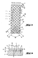
- - FIG 3 : une vue de dessus, à une plus grande échelle et suivant le secteur III, du cadre représenté à la figure 1.
- - FIG 4 : le cadre représenté à la figure 3 en coupe suivant la ligne IV - IV.
- - FIG 1: a frame mounted on a mobile carriage shown in perspective.
- - FIG 2: a section along line 11-11 of the frame shown in Figure 1.
- FIG. 3: a top view, on a larger scale and along sector III, of the frame shown in FIG. 1.
- - FIG 4: the frame shown in Figure 3 in section along line IV - IV.
Les cadres selon l'art sont habituellement utilisés pour le transport de feuilles de verre bombées, directement du dispositif de bombage au dispositif de trempe qui comme tel comprend deux caissons de soufflage avec des buses ou ouvertures dirigées vers la feuille de verre et dans lequel est obtenu un refroidissement brusque de la feuille de verre dans le but de la trempe. Le cadre 1 est, par exemple, fixé d'une manière adéquate sur un chariot de transport 2. Ce dernier est muni de roues 3 qui permettent de le déplacer, sur les rails 4 qui relient la station de bombage à celle de trempe. Par des moyens de commande ici non représentés, le chariot de transport 2 est conduit du poste de bombage au poste de trempe, et de là au poste de déchargement dans lequel la feuille de verre trempée est retirée du cadre 1.Frames according to the art are usually used for the transport of curved glass sheets, directly from the bending device to the tempering device which as such comprises two blowing boxes with nozzles or openings directed towards the glass sheet and in which is obtained a sudden cooling of the glass sheet for the purpose of tempering. The
Le cadre 1 peut servir à la prise en charge de feuilles de verre préalablement bombées au moyen d'une presse de bombage ou tout autre moyen. Il peut aussi servir lui-même de forme de bombage, la feuille de verre étant soulevée avec ce cadre 1 et pressée confie une surface de bombage de forme correspondante à celle du cadre 1, ou encore échauffée jusqu'à sa température de bombage, encore plane, la feuille de verre étant lachée (en position horizontale), sur le cadre 1 d'une hauteur adéquate. Ce dernier procédé de bombage est, comme les précédents, bien connu et usuel.The
Enfin le cadre 1 peut aussi être utilisé pour transporter les feuilles de verre 6 pendant tout leur trajet à travers les fours d'échauffement et de bombage et la station de trempe qui s'y rapporte. En d'autres termes, le cadre selon l'invention est utilisable indépendamment du procédé de bombage appliqué et peut même l'être pour la trempe de feuilles de verre planes.Finally, the
Le cadre 1 peut être fabrique d'une seule pièce ou se composer de plusieurs segments assemblés en forme d'anneau fermé. Il s'agit d'une construction robuste, relativement nassive afin de réduire, si ce n'est d'exclure totalement, le danger d'une déformation du cadre due aux contraintes thermiques ou mécaniques.The
Le matériau utilisé pour la construction du cadre 1 doit se prêter à un travail précis avec l'outillage habituel afin d'obtenir avec haute précision la forme souhaitée de la surface porteuse. En outre pour certaines utilisations particulières du cadre, ce matériau doit présenter une conductivité thermique relativement faible, car des difficultés peuvent surgir avec des matériaux bons conducteurs de la chaleur dans le cas où la feuille de verre, fortement échauffée, est posée sur un cadre, porté à une température relativement basse. Conviennent alors les matériaux-céramiques, pouvant se travailler avec des machines-outil d'usinage, aisni que les alliages de fer ou les aciers spéciaux à faible conductibilité thermique et à faible coefficient de diffusité tel que l'acier réfractaire Fluginox N42 (marque déposée).The material used for the construction of the
Sur la surface supérieure du cadre 1, suivant un agencement régulier et dense, est disposée une pluralité de portées (8), dirigées vers le haut verticalement et dont les surfaces supérieures forment en commun la surface de pose de la bordure de la feuille de verre (6). Dans la plupart des cas il est suffisant que la feuille de verre (6) ne repose sur les portées (8) que le long d'une bordure, sur une largeur A d'environ 10 à 15 mm. La largeur B de la partie portante du cadre 1, formée par l'ensemble des portées 8 est, d'une manière appropriée un peu plus importante que la largeur A recouverte par la feuille de verre. Les portées 8 ont une hauteur H comprise entre 2 et 10 mm et dans les intervalles entre les portées se forme un réseau de canaux à travers lequel s'évacue l'air de refroidissement dirigé vers la surface inférieure de la feuille de verre et provenant des buses de soufflage 1 du caisson inférieure 12, comme l'illustre en particulier la figure 2.On the upper surface of the
Comme il ressort en détail sur les figures 3 et 4, afin d'obtenir un refroidissement si possible homogène des bords de la feuille dans la zone de pose, les rangées R et S de portées 8 sont disposées l'une derrière l'autre dans la direction du courant d'air (flèche F) et de plus leur positionnement est tel que chaque portée (8) de la rangée S soit dans le prolongement d'une lacune entre deux portées de la rangée R. De cette manitre, en s'évacuant dans la direction de la flèche F selon la direction d'écoulement radiale originale, l'air rencontre des obstacles qui le contraignent à s'écouler au travers du réseau de canaux, dans les canaux 14, 15 qui se croisent à l'angle droit, avec à chaque embranchement une distribution constante de l'air. Les canaux 14, 15 passent sous un angle d'environ 45° par rapport à la section correspondante de cadre.As can be seen in detail in FIGS. 3 and 4, in order to obtain, if possible, uniform cooling of the edges of the sheet in the laying area, the rows R and S of
De bons résultats sont obtenus lorsque les portées présentent une hauteur H comprise entre 3 et 6 mm et une section approximativement carrée de l'ordre de 2 à 10 mm2 et de préférence de 3 à 6 mm2 soit par exemple avec une valeur L de coté d'environ 2 mm, alors que la largeur M des canaux 14, 15, entre les portées, est de même de l'ordre de 2 mm. De cette manière on a un réseau de canaux d'écoulement, où le volume occupé par les portées totalise 1/3 du volume occupé par les canaux d'écoulement. Ainsi on obtient simultanément une surface de pose suffisante pour la feuille de verre et des canaux de sections suffisantes pour une bonne évacuation des gaz de soufflage.Good results are obtained when the spans have a height H of between 3 and 6 mm and an approximately square section of the order of 2 to 10 mm 2 and preferably from 3 to 6 mm2, for example with a value L on the side approximately 2 mm, while the width M of the
Comme déjà mentionné, les matériaux de construction du cadre qui conviennent sont les composés céramiques ou métalliques usinables avec les machines outils usuelles. Les canaux 14, 15 seront par exemple obtenus pour fraisage à l'aide d'une fraiseuse adéquate.As already mentioned, the suitable frame construction materials are ceramic or metal compounds which can be machined with conventional machine tools. The
Si la cadre est utilisé pour un procédé selon lequel la feuille de verre, échauffée jusqu'à sa température de bombage, est amenée au contact du cadre se trouvant à relativement basse température, alors il faut choisir un matériau adéquat, présentant une faible conductibilité thermique ce qui évite un trop fort refroidissement de la feuille de verre lors du contact avec le cadre, refroidissement qui pourrait entrafner la casse de la feuille de verre. Si le matériau choisi présente une conductibilité thermique relativement élevée, il est recommandé de munir la surface de pose des portées d'un revêtement en céramique, obtenu par exemple au moyen du procédé connu de pulvérisation à la torche à plasma. Une autre solution consiste dans le choix pour la fabrication de tout le cadre d'un composé métallique présentant une relativement faible conductibilité thermique, comme par exemple un alliage d'acier spécial, ou d'un composé céramique adéquat. Enfin il est aussi possible d'utiliser comme portées des chevilles en céramique qui sont placées dans des perforations prévues dans un corps de cadre métallique.If the frame is used for a process in which the glass sheet, heated to its bending temperature, is brought into contact with the frame being at relatively low temperature, then an appropriate material must be chosen, having a low thermal conductivity which avoids excessive cooling of the glass sheet during contact with the frame, cooling which could cause breakage of the glass sheet. If the material chosen has a relatively high thermal conductivity, it is recommended to provide the bearing surface of the surfaces with a ceramic coating, obtained for example by means of the known process of spraying with a plasma torch. Another solution consists in the choice for the manufacture of the entire frame of a metallic compound having a relatively low thermal conductivity, such as for example a special steel alloy, or of a suitable ceramic compound. Finally it is also possible to use as bearings ceramic pegs which are placed in perforations provided in a metal frame body.
Claims (10)
Priority Applications (1)
| Application Number | Priority Date | Filing Date | Title |
|---|---|---|---|
| AT85402080T ATE31712T1 (en) | 1984-10-29 | 1985-10-28 | FRAME FOR SUPPORTING A GLASS PLATE DURING TEMPERING. |
Applications Claiming Priority (2)
| Application Number | Priority Date | Filing Date | Title |
|---|---|---|---|
| FR8416482A FR2572388B1 (en) | 1984-10-29 | 1984-10-29 | SUPPORT FRAME FOR A GLASS SHEET DURING THE TEMPERING |
| FR8416482 | 1984-10-29 |
Publications (2)
| Publication Number | Publication Date |
|---|---|
| EP0186529A1 true EP0186529A1 (en) | 1986-07-02 |
| EP0186529B1 EP0186529B1 (en) | 1988-01-07 |
Family
ID=9309067
Family Applications (1)
| Application Number | Title | Priority Date | Filing Date |
|---|---|---|---|
| EP85402080A Expired EP0186529B1 (en) | 1984-10-29 | 1985-10-28 | Frame for supporting a sheet of glass during tempering |
Country Status (7)
| Country | Link |
|---|---|
| US (1) | US4661142A (en) |
| EP (1) | EP0186529B1 (en) |
| JP (1) | JPH0699161B2 (en) |
| AT (1) | ATE31712T1 (en) |
| DE (2) | DE3536783A1 (en) |
| FI (1) | FI78668C (en) |
| FR (1) | FR2572388B1 (en) |
Cited By (2)
| Publication number | Priority date | Publication date | Assignee | Title |
|---|---|---|---|---|
| FR2677015A1 (en) * | 1991-05-30 | 1992-12-04 | Saint Gobain Vitrage Int | COATING FOR ANNULAR BOMBING / TEMPERING MOLDS. |
| WO1999020575A1 (en) * | 1997-10-22 | 1999-04-29 | Saint-Gobain Vitrage | Method and device for curving and tempering a glass sheet |
Families Citing this family (15)
| Publication number | Priority date | Publication date | Assignee | Title |
|---|---|---|---|---|
| DE3721306C1 (en) * | 1987-06-27 | 1989-01-26 | Flachglas Ag | Support ring for a hot glass pane during thermal prestressing |
| FR2642417B1 (en) * | 1988-12-21 | 1993-10-15 | Saint Gobain Vitrage | SUPPORT FRAME OF A GLASS SHEET |
| DE3923564C1 (en) * | 1989-07-17 | 1991-01-17 | Riedhammer Gmbh Und Co Kg, 8500 Nuernberg, De | |
| DE3927928A1 (en) * | 1989-08-24 | 1991-02-28 | Gutehoffnungshuette Man | AIR COOLING SYSTEM FOR METALLURGICAL VESSELS STORED IN A CARRIER |
| US5385786A (en) * | 1993-02-09 | 1995-01-31 | Glasstech, Inc. | Apparatus and method for controlling stresses in laminated automotive glass |
| DE4325076A1 (en) * | 1993-07-19 | 1995-01-26 | Faba Autoglas Technik Gmbh & C | Carrying element for a heated glass sheet |
| US5383950A (en) * | 1993-10-04 | 1995-01-24 | Ford Motor Company | Apparatus for supporting a glass sheet during a tempering process |
| US5679124A (en) * | 1995-08-02 | 1997-10-21 | Glasstech, Inc. | Cooling ring assembly for controlling stresses in a formed glass sheet |
| DE19547935C1 (en) * | 1995-12-22 | 1997-03-20 | Sekurit Saint Gobain Deutsch | Glass sheet supporting mould ring |
| FR2768142B1 (en) * | 1997-09-11 | 1999-11-05 | Saint Gobain Vitrage | DEVICE FOR COOLING BOMBED GLASS SHEETS |
| JP3681312B2 (en) | 1999-08-16 | 2005-08-10 | セントラル硝子株式会社 | Glass plate support frame |
| FR2942793B1 (en) * | 2009-03-05 | 2012-03-23 | Saint Gobain | FORMING A GLAZING COMPRISING AN OPENING |
| WO2014109237A1 (en) * | 2013-01-11 | 2014-07-17 | 旭硝子株式会社 | Manufacturing method and manufacturing device for toughened glass |
| WO2016019209A1 (en) | 2014-08-01 | 2016-02-04 | Corning Incorporated | Glass shaping apparatus and method |
| BR112019010702A2 (en) * | 2017-02-20 | 2019-10-01 | Saint Gobain | tempering frame for tempering glass panels |
Citations (2)
| Publication number | Priority date | Publication date | Assignee | Title |
|---|---|---|---|---|
| US2032008A (en) * | 1934-10-13 | 1936-02-25 | Pittsburgh Plate Glass Co | Apparatus for case hardening glass |
| US3973943A (en) * | 1975-03-12 | 1976-08-10 | Ppg Industries, Inc. | Apparatus for supporting shaped glass sheets for tempering |
Family Cites Families (4)
| Publication number | Priority date | Publication date | Assignee | Title |
|---|---|---|---|---|
| GB505189A (en) * | 1937-11-05 | 1939-05-05 | Manufacturers Des Glaces Et Pr | Improvements in and relating to apparatus for chilling glass for tempering |
| US3741743A (en) * | 1972-07-31 | 1973-06-26 | S Seymour | Glass sheet shaping frame |
| JPS5935539Y2 (en) * | 1980-03-12 | 1984-10-01 | セントラル硝子株式会社 | Glass plate bending device |
| JPS593939A (en) * | 1982-06-29 | 1984-01-10 | Marine Instr Co Ltd | Control of loop height at wire bonder |
-
1984
- 1984-10-29 FR FR8416482A patent/FR2572388B1/en not_active Expired
-
1985
- 1985-10-16 DE DE19853536783 patent/DE3536783A1/en active Granted
- 1985-10-28 JP JP60239624A patent/JPH0699161B2/en not_active Expired - Lifetime
- 1985-10-28 AT AT85402080T patent/ATE31712T1/en not_active IP Right Cessation
- 1985-10-28 FI FI854222A patent/FI78668C/en not_active IP Right Cessation
- 1985-10-28 US US06/791,971 patent/US4661142A/en not_active Expired - Lifetime
- 1985-10-28 DE DE8585402080T patent/DE3561311D1/en not_active Expired
- 1985-10-28 EP EP85402080A patent/EP0186529B1/en not_active Expired
Patent Citations (2)
| Publication number | Priority date | Publication date | Assignee | Title |
|---|---|---|---|---|
| US2032008A (en) * | 1934-10-13 | 1936-02-25 | Pittsburgh Plate Glass Co | Apparatus for case hardening glass |
| US3973943A (en) * | 1975-03-12 | 1976-08-10 | Ppg Industries, Inc. | Apparatus for supporting shaped glass sheets for tempering |
Cited By (4)
| Publication number | Priority date | Publication date | Assignee | Title |
|---|---|---|---|---|
| FR2677015A1 (en) * | 1991-05-30 | 1992-12-04 | Saint Gobain Vitrage Int | COATING FOR ANNULAR BOMBING / TEMPERING MOLDS. |
| EP0521741A1 (en) * | 1991-05-30 | 1993-01-07 | Saint-Gobain Vitrage | Liner for annular bending/temporing moulds |
| US5328496A (en) * | 1991-05-30 | 1994-07-12 | Saint-Gobain Vitrage International | Apparatus including mold having covering for annular bending/tempering molds |
| WO1999020575A1 (en) * | 1997-10-22 | 1999-04-29 | Saint-Gobain Vitrage | Method and device for curving and tempering a glass sheet |
Also Published As
| Publication number | Publication date |
|---|---|
| FI854222A0 (en) | 1985-10-28 |
| DE3536783C2 (en) | 1987-05-07 |
| JPH0699161B2 (en) | 1994-12-07 |
| FR2572388A1 (en) | 1986-05-02 |
| EP0186529B1 (en) | 1988-01-07 |
| DE3561311D1 (en) | 1988-02-11 |
| JPS61106431A (en) | 1986-05-24 |
| FR2572388B1 (en) | 1986-12-26 |
| US4661142A (en) | 1987-04-28 |
| DE3536783A1 (en) | 1986-04-30 |
| FI78668B (en) | 1989-05-31 |
| FI854222L (en) | 1986-04-30 |
| ATE31712T1 (en) | 1988-01-15 |
| FI78668C (en) | 1989-09-11 |
Similar Documents
| Publication | Publication Date | Title |
|---|---|---|
| EP0186529B1 (en) | Frame for supporting a sheet of glass during tempering | |
| EP0255422B1 (en) | Bending of glass sheets | |
| EP0169770B1 (en) | Method and apparatus for bending glass sheets into a horizontal position | |
| FR2707283A1 (en) | Process and device for forming glass plates and application of this method to obtaining glazings of complex shapes. | |
| EP0810978B1 (en) | Method for bending and/or tempering sheet glass and bending frame therefor | |
| WO2002055444A1 (en) | Method for cutting the edges of a continuous glass ribbon, a device for implementing said method, and a glass plate cut using said method | |
| CA2019486C (en) | Process and apparatus for effecting curving and tempering by contact | |
| EP0240418B1 (en) | Method and apparatus for shaping glass | |
| EP0277074A1 (en) | Volumes of glass tempered by contact with reinforced rims | |
| FR2504689A1 (en) | MIRROR LIGHT MIRROR FOR ASTRONOMY AND PROCESS FOR PRODUCING SAME FOR SUCH | |
| EP0256905A1 (en) | Positioning glass sheets before bending them | |
| EP0939744B1 (en) | Device for cooling convex glass sheets | |
| EP1611065B1 (en) | Method and device for bending glass sheets | |
| US20150068250A1 (en) | Method for producing float glass | |
| EP1127654B1 (en) | Metal sheet butt welding method and apparatus | |
| EP0761829A1 (en) | Cooling device for rolled products | |
| EP0262046B1 (en) | Method and apparatus for bending glass sheets | |
| EP1025055A1 (en) | Method and device for curving and tempering a glass sheet | |
| CA2019487C (en) | Apparatus for contact tempering of glass | |
| EP3947302A1 (en) | Conveying sheets of glass using shaped rollers | |
| EP0170585B1 (en) | Temperature-homogenizing device for continuously moving metallic products | |
| CA1243456A (en) | Method for producing a clad plate by rolling | |
| WO2021260083A1 (en) | Glass sheet bending mould comprising a heating circuit and a cooling circuit | |
| CN217535820U (en) | Device for improving quality of end part of borosilicate glass tube | |
| EP0494823A2 (en) | Method and apparatus for treating hot glass sheets |
Legal Events
| Date | Code | Title | Description |
|---|---|---|---|
| PUAI | Public reference made under article 153(3) epc to a published international application that has entered the european phase |
Free format text: ORIGINAL CODE: 0009012 |
|
| 17P | Request for examination filed |
Effective date: 19860401 |
|
| AK | Designated contracting states |
Kind code of ref document: A1 Designated state(s): AT BE CH DE FR GB IT LI SE |
|
| 17Q | First examination report despatched |
Effective date: 19870318 |
|
| GRAA | (expected) grant |
Free format text: ORIGINAL CODE: 0009210 |
|
| AK | Designated contracting states |
Kind code of ref document: B1 Designated state(s): AT BE CH DE FR GB IT LI SE |
|
| PG25 | Lapsed in a contracting state [announced via postgrant information from national office to epo] |
Ref country code: AT Effective date: 19880107 |
|
| REF | Corresponds to: |
Ref document number: 31712 Country of ref document: AT Date of ref document: 19880115 Kind code of ref document: T |
|
| PG25 | Lapsed in a contracting state [announced via postgrant information from national office to epo] |
Ref country code: SE Effective date: 19880131 |
|
| REF | Corresponds to: |
Ref document number: 3561311 Country of ref document: DE Date of ref document: 19880211 |
|
| GBT | Gb: translation of ep patent filed (gb section 77(6)(a)/1977) | ||
| ITF | It: translation for a ep patent filed |
Owner name: DR. ING. A. RACHELI & C. |
|
| PG25 | Lapsed in a contracting state [announced via postgrant information from national office to epo] |
Ref country code: LI Effective date: 19881031 Ref country code: CH Effective date: 19881031 |
|
| PLBE | No opposition filed within time limit |
Free format text: ORIGINAL CODE: 0009261 |
|
| STAA | Information on the status of an ep patent application or granted ep patent |
Free format text: STATUS: NO OPPOSITION FILED WITHIN TIME LIMIT |
|
| 26N | No opposition filed | ||
| REG | Reference to a national code |
Ref country code: CH Ref legal event code: PL |
|
| ITTA | It: last paid annual fee | ||
| PGFP | Annual fee paid to national office [announced via postgrant information from national office to epo] |
Ref country code: GB Payment date: 20010924 Year of fee payment: 17 |
|
| PGFP | Annual fee paid to national office [announced via postgrant information from national office to epo] |
Ref country code: DE Payment date: 20011106 Year of fee payment: 17 |
|
| REG | Reference to a national code |
Ref country code: GB Ref legal event code: IF02 |
|
| PGFP | Annual fee paid to national office [announced via postgrant information from national office to epo] |
Ref country code: FR Payment date: 20021004 Year of fee payment: 18 |
|
| PGFP | Annual fee paid to national office [announced via postgrant information from national office to epo] |
Ref country code: BE Payment date: 20021022 Year of fee payment: 18 |
|
| PG25 | Lapsed in a contracting state [announced via postgrant information from national office to epo] |
Ref country code: GB Free format text: LAPSE BECAUSE OF NON-PAYMENT OF DUE FEES Effective date: 20021028 |
|
| PG25 | Lapsed in a contracting state [announced via postgrant information from national office to epo] |
Ref country code: DE Free format text: LAPSE BECAUSE OF NON-PAYMENT OF DUE FEES Effective date: 20030501 |
|
| GBPC | Gb: european patent ceased through non-payment of renewal fee | ||
| PG25 | Lapsed in a contracting state [announced via postgrant information from national office to epo] |
Ref country code: BE Free format text: LAPSE BECAUSE OF NON-PAYMENT OF DUE FEES Effective date: 20031031 |
|
| BERE | Be: lapsed |
Owner name: *SAINT-GOBAIN VITRAGE Effective date: 20031031 |
|
| PG25 | Lapsed in a contracting state [announced via postgrant information from national office to epo] |
Ref country code: FR Free format text: LAPSE BECAUSE OF NON-PAYMENT OF DUE FEES Effective date: 20040630 |
|
| REG | Reference to a national code |
Ref country code: FR Ref legal event code: ST |