EP0186423A2 - Lift-truck - Google Patents
Lift-truck Download PDFInfo
- Publication number
- EP0186423A2 EP0186423A2 EP85309207A EP85309207A EP0186423A2 EP 0186423 A2 EP0186423 A2 EP 0186423A2 EP 85309207 A EP85309207 A EP 85309207A EP 85309207 A EP85309207 A EP 85309207A EP 0186423 A2 EP0186423 A2 EP 0186423A2
- Authority
- EP
- European Patent Office
- Prior art keywords
- lift
- truck
- retarder
- drive train
- truck according
- Prior art date
- Legal status (The legal status is an assumption and is not a legal conclusion. Google has not performed a legal analysis and makes no representation as to the accuracy of the status listed.)
- Withdrawn
Links
Images

Classifications
-
- H—ELECTRICITY
- H05—ELECTRIC TECHNIQUES NOT OTHERWISE PROVIDED FOR
- H05K—PRINTED CIRCUITS; CASINGS OR CONSTRUCTIONAL DETAILS OF ELECTRIC APPARATUS; MANUFACTURE OF ASSEMBLAGES OF ELECTRICAL COMPONENTS
- H05K7/00—Constructional details common to different types of electric apparatus
Definitions
- the invention relates to lift-trucks for load handling. Such trucks are normally fitted with lifting forks on which a load is raised and transported.
- the present invention provides a lift-truck wherein the problems caused by heavy braking during such operations are overcome.
- a lift-truck having means such as forks on which a load may be raised and transported, the lift-truck comprising a drive train connected between a prime mover and at least one pair of drive wheels wherein electromagnetic retarder is coupled in the drive train whereby an electromagnetic braking effect may be selectively applied to the drive train.
- the drive train of the lift-truck may take any suitable form and will normally comprise a gearbox connected via propellor shafts to an axle mounted differential; the drive wheels being located at opposite ends of the axle. In many cases the drive wheels of lift-trucks are dirigible and in this case the wheels will be coupled to the drive train through universal joints.
- the position of the electromagnetic retarder in the drive train will be selected according to convenience and cost and it may suitably be provided mounted on the gearbox, mounted between propellor shafts, or mounted on the axle. If the axle incorporates a differential drive the retarder may be mounted directly thereon.
- Operation of the electromagnetic retarder may be governed by manual operation of a control lever and/or by the operation of a brake sensor.
- a speed sensitive cut out device may be fitted to disconnect the electromagnetic retarder at vehicle speeds below a predetermined minimum so as to prevent overheating of the retarder through prolonged operation when the vehicle is stationery.
- FIGS 1 to 3 Three possible arrangements of the retarder in a drive train are shown in Figures 1 to 3.
- the retarder 1 is connected directly onto the output shaft of the gearbox 2 and is coupled to a drive axle 3 by means of a propellor shaft 4.
- the propellor shaft may have splined couplings 5 and universal couplings 6 to allow for movement of the different parts of the drive train relative to the chassis of the truck.
- the retarder will be connected to the frame or chassis of the vehicle so that the non-rotating parts of the retarder may be held stationary.
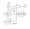
- FIG. 4 shows, diagrammatically, how the retarder is brought into operation.
- a battery 10 which may suitably be a 12 or 24 volt battery is coupled via a relay box 9 to the coils of the electromagnetic retarder.
- the retarder is provided with eight coils arranged around its axis, and the coils are coupled in pairs to the battery 10 via four relays in the relay box 9.
- the number of coils energised at any one time via the relay box will be dependent of the operation of a control system 7 comprising a manually operated lever 8.
- the lever 8 has five different possible positions; in a first position none of the relays in the relay box is energised, and consequently none of the coils of the retarder are connected to the battery.
- a speed sensitive cut-out device 11 is fitted to prevent overheating of the retarder through prolonged operation when the vehicle is stationary. This removes the control signal to the retarder at vehicle speeds below a predetermined minimum, eg 1 kph.
- Motion may be sensed from rotation of propshaft, out-put of transmission or wheel rotation, by a motion sensor 12, connected to a cut-out device 11.
- the motion sensor may be a magnetic switch, a proximity device, an optical switch, or a power generator.
- a controller in the cut-out device senses the strength of the signal from the sensor 11 and switches the retarder operating relays accordingly.
- the relay box may be operated by a brake sensor 13 coupled to the foot brake lever of the lift truck such that over the initial travel of the lever before the conventional brakes are engaged, the retarder is progressively introduced to provide smooth braking.
- the brake sensor may be provided in addition to the control system 7.
- control system 7 is coupled to the accelerator pedal of the lift truck such that the retarder is automatically brought into operation when the pedal is released.
- the main parts of the retarder are a shaft, coils, stator and a pair of vaned cooling rotors. None of these parts are shown in the accompanying drawings in which the retarder is shown only schematically.
Abstract
A lift-truck is provided with an electromagnetic retarder (1) coupled in its drive train so that an electromagnetic braking effect may be applied thereto. The retarder may be mounted on the gearbox (2), in the propellor shaft (4), or on an axle (3) of the vehicle. The retarder may be operated by a hand lever (8) or may be connected to the brake pedal or accelerator pedal of the lift-truck.
Description
- The invention relates to lift-trucks for load handling. Such trucks are normally fitted with lifting forks on which a load is raised and transported.
- Very substantial loads may be carried by such trucks and the size of these loads when added to the weight of the truck can provide a formidable braking problem. This position is particularly exacerbated in so called roll-on/roll-off operations for loading and unloading cargo carrying vessels. In these operations the trucks will continuously carry heavy loads up and down a relatively steep ramp. The braking need during such operations is extremely high and the wear on conventional braking systems and the need for servicing and replacement are correspondingly increased.
- The present invention provides a lift-truck wherein the problems caused by heavy braking during such operations are overcome.
- According to the present invention there is provided a lift-truck having means such as forks on which a load may be raised and transported, the lift-truck comprising a drive train connected between a prime mover and at least one pair of drive wheels wherein electromagnetic retarder is coupled in the drive train whereby an electromagnetic braking effect may be selectively applied to the drive train.
- The drive train of the lift-truck may take any suitable form and will normally comprise a gearbox connected via propellor shafts to an axle mounted differential; the drive wheels being located at opposite ends of the axle. In many cases the drive wheels of lift-trucks are dirigible and in this case the wheels will be coupled to the drive train through universal joints.
- The position of the electromagnetic retarder in the drive train will be selected according to convenience and cost and it may suitably be provided mounted on the gearbox, mounted between propellor shafts, or mounted on the axle. If the axle incorporates a differential drive the retarder may be mounted directly thereon.
- Operation of the electromagnetic retarder may be governed by manual operation of a control lever and/or by the operation of a brake sensor.
- Advantageously a speed sensitive cut out device may be fitted to disconnect the electromagnetic retarder at vehicle speeds below a predetermined minimum so as to prevent overheating of the retarder through prolonged operation when the vehicle is stationery.
- A detailed desciption of embodiments of the present invention is given below with reference to the accompanying drawings in which:
- Figure 1 shows diagrammatically the drive train of a lift-truck with a retarder completed therein,
- Figure 2 shows an alternative to the arrangement in Figure 1,
- Figure 3 shows a further alternative, and
- Figure 4 is a box-diagram showing the operation and control of the retarder.
- Three possible arrangements of the retarder in a drive train are shown in Figures 1 to 3. In Figure 1 the
retarder 1 is connected directly onto the output shaft of thegearbox 2 and is coupled to adrive axle 3 by means of a propellor shaft 4. The propellor shaft may have splinedcouplings 5 anduniversal couplings 6 to allow for movement of the different parts of the drive train relative to the chassis of the truck. - In Figure 2 the retarder is mounted in the propeller shaft 4.
- In Figure 3 the retarder is mounted on the
axle 3. - In each case the retarder will be connected to the frame or chassis of the vehicle so that the non-rotating parts of the retarder may be held stationary.
- Figure 4 shows, diagrammatically, how the retarder is brought into operation. A
battery 10 which may suitably be a 12 or 24 volt battery is coupled via a relay box 9 to the coils of the electromagnetic retarder. In one example, the retarder is provided with eight coils arranged around its axis, and the coils are coupled in pairs to thebattery 10 via four relays in the relay box 9. The number of coils energised at any one time via the relay box will be dependent of the operation of acontrol system 7 comprising a manually operatedlever 8. In the example described thelever 8 has five different possible positions; in a first position none of the relays in the relay box is energised, and consequently none of the coils of the retarder are connected to the battery. In this "off" position the retarder applies no electromagnetic braking effect to the drive train. The other four positions of thelever 8 correspond to the progressive braking modes of the retarder wherein two, four, six, or all eight of the coils are energised by the battery. - In the embodiment shown, a speed sensitive cut-out
device 11 is fitted to prevent overheating of the retarder through prolonged operation when the vehicle is stationary. This removes the control signal to the retarder at vehicle speeds below a predetermined minimum, eg 1 kph. Motion may be sensed from rotation of propshaft, out-put of transmission or wheel rotation, by amotion sensor 12, connected to a cut-outdevice 11. - The motion sensor may be a magnetic switch, a proximity device, an optical switch, or a power generator.
- A controller in the cut-out device senses the strength of the signal from the
sensor 11 and switches the retarder operating relays accordingly. - In an alternative embodiment, shown in dotted lines in Figure 4, the relay box may be operated by a
brake sensor 13 coupled to the foot brake lever of the lift truck such that over the initial travel of the lever before the conventional brakes are engaged, the retarder is progressively introduced to provide smooth braking. Although shown as alternative, the brake sensor may be provided in addition to thecontrol system 7. - In yet another embodiment, not shown, the
control system 7 is coupled to the accelerator pedal of the lift truck such that the retarder is automatically brought into operation when the pedal is released. - The main parts of the retarder are a shaft, coils, stator and a pair of vaned cooling rotors. None of these parts are shown in the accompanying drawings in which the retarder is shown only schematically.
Claims (9)
1. A lift-truck having means such as forks on which a load may be raised and transported, the lift-truck comprising a drive train connected between a prime mover and at least one pair of drive wheels characterised in that an electromagnetic retarder is coupled in the drive train whereby an electromagnetic braking effect may be selectively applied to the drive train.
2. A lift-truck according to Claim 1, wherein the drive train comprises a gearbox, at least one propellor shaft, and an axle, and wherein the electromagnetic retarder is mounted on the gearbox.
3. A lift-truck according to Claim 1, wherein the drive train comprises a gearbox, at least one propellor shaft, and an axle, and wherein the electromagnetic retarder is mounted in the propellor shaft.
4. A lift-truck according to Claim 1, wherein the drive train comprises a gearbox, at least one propellor shaft, and an axle, and wherein the electromagnetic retarder is mounted on the axle.
5. A lift-truck according to any preceding claim, wherein the braking effect of the electromagnetic retarder is governed by a manually operated control lever.
6. A lift-truck according to any of Claims 1 - 5, wherein the braking effect of the electromagnetic retarder is governed by operation of a brake sensor coupled to of the pedal by which the conventional braking system of the lift-truck is also operated.
7. A lift-truck according to any of Claims 1 to 4, wherein the braking effect of the electromagnetic retarder is governed by operation of the accelerator pedal of the lift-truck.
8. A lift truck according to any preceding claim wherein a speed sensitive cut-out device is fitted to cut out the electromagnetic retarder at vehicle speeds below a predetermined minimum to prevent overheating of the retarder through prolonged operation when the vehicle is stationery.
9. A lift-truck according to any preceding claim comprising a generally rectangular chassis with at least one wheel located adjacent each corner thereof and a load handling carriage mounted at one end of the chassis, wherein the wheels at the end of the chassis adjacent the carriage are driven, and the wheels at the other end are dirigible.
Applications Claiming Priority (2)
| Application Number | Priority Date | Filing Date | Title |
|---|---|---|---|
| GB08432431A GB2168657A (en) | 1984-12-21 | 1984-12-21 | Brake system of lift-truck |
| GB8432431 | 1984-12-21 |
Publications (2)
| Publication Number | Publication Date |
|---|---|
| EP0186423A2 true EP0186423A2 (en) | 1986-07-02 |
| EP0186423A3 EP0186423A3 (en) | 1988-10-19 |
Family
ID=10571613
Family Applications (1)
| Application Number | Title | Priority Date | Filing Date |
|---|---|---|---|
| EP85309207A Withdrawn EP0186423A3 (en) | 1984-12-21 | 1985-12-17 | Lift-truck |
Country Status (5)
| Country | Link |
|---|---|
| EP (1) | EP0186423A3 (en) |
| DE (1) | DE8432431U1 (en) |
| FI (1) | FI855108A (en) |
| GB (1) | GB2168657A (en) |
| NO (1) | NO855152L (en) |
Cited By (1)
| Publication number | Priority date | Publication date | Assignee | Title |
|---|---|---|---|---|
| DE102007046852A1 (en) * | 2007-09-29 | 2009-04-02 | Bayerische Motoren Werke Aktiengesellschaft | Motor vehicle, has controllable and/or regulatable eddy-current brake formed by electromagnets combined together with rotating part, which is functional integral part of internal combustion engine or drive device |
Citations (9)
| Publication number | Priority date | Publication date | Assignee | Title |
|---|---|---|---|---|
| DE811913C (en) * | 1949-07-15 | 1951-08-23 | Garbe | Electric braking device for land vehicles especially driven by internal combustion engines |
| DE937181C (en) * | 1952-05-04 | 1955-12-29 | Cie Telma | Electric eddy current brakes, especially for vehicles |
| FR1547016A (en) * | 1967-12-08 | 1968-11-22 | Saurer Ag Adolph | continuous brake equipment on motor vehicle gearbox |
| US3416016A (en) * | 1965-01-11 | 1968-12-10 | Hitachi Ltd | Speed reduction apparatus for automotive vehicles |
| FR2100428A5 (en) * | 1970-07-09 | 1972-03-17 | Telesforo Gorostiza | |
| GB1524452A (en) * | 1976-03-18 | 1978-09-13 | Lafuente Ruberte A | Retarding mechanisms for vehicles |
| DE2929290A1 (en) * | 1978-07-20 | 1980-02-07 | Labavia | BRAKE DEVICE, IN PARTICULAR FOR A VEHICLE |
| DE3108732A1 (en) * | 1981-03-07 | 1982-09-23 | Lothar Kloft KG, 6251 Selters | Circuit for actuating an eddy current brake for motor vehicles |
| GB2099093A (en) * | 1981-05-05 | 1982-12-01 | Labavia | Improvements to retarder equipment for vehicles |
Family Cites Families (3)
| Publication number | Priority date | Publication date | Assignee | Title |
|---|---|---|---|---|
| FR1386434A (en) * | 1963-12-10 | 1965-01-22 | Labavia | Improvements to eddy current retarder devices |
| FR1521399A (en) * | 1967-01-18 | 1968-04-19 | Labavia | Improvements to transmissions of vehicles fitted with retarders and their control devices |
| ES500015A0 (en) * | 1981-03-03 | 1982-11-01 | Frenos Electricos Unidos S A F | AXLE IMPROVEMENTS FOR VEHICLES WITH BUILT-IN ELECTRIC BRAKE |
-
1984
- 1984-11-06 DE DE8432431U patent/DE8432431U1/en not_active Expired
- 1984-12-21 GB GB08432431A patent/GB2168657A/en not_active Withdrawn
-
1985
- 1985-12-17 EP EP85309207A patent/EP0186423A3/en not_active Withdrawn
- 1985-12-19 NO NO855152A patent/NO855152L/en unknown
- 1985-12-20 FI FI855108A patent/FI855108A/en not_active Application Discontinuation
Patent Citations (9)
| Publication number | Priority date | Publication date | Assignee | Title |
|---|---|---|---|---|
| DE811913C (en) * | 1949-07-15 | 1951-08-23 | Garbe | Electric braking device for land vehicles especially driven by internal combustion engines |
| DE937181C (en) * | 1952-05-04 | 1955-12-29 | Cie Telma | Electric eddy current brakes, especially for vehicles |
| US3416016A (en) * | 1965-01-11 | 1968-12-10 | Hitachi Ltd | Speed reduction apparatus for automotive vehicles |
| FR1547016A (en) * | 1967-12-08 | 1968-11-22 | Saurer Ag Adolph | continuous brake equipment on motor vehicle gearbox |
| FR2100428A5 (en) * | 1970-07-09 | 1972-03-17 | Telesforo Gorostiza | |
| GB1524452A (en) * | 1976-03-18 | 1978-09-13 | Lafuente Ruberte A | Retarding mechanisms for vehicles |
| DE2929290A1 (en) * | 1978-07-20 | 1980-02-07 | Labavia | BRAKE DEVICE, IN PARTICULAR FOR A VEHICLE |
| DE3108732A1 (en) * | 1981-03-07 | 1982-09-23 | Lothar Kloft KG, 6251 Selters | Circuit for actuating an eddy current brake for motor vehicles |
| GB2099093A (en) * | 1981-05-05 | 1982-12-01 | Labavia | Improvements to retarder equipment for vehicles |
Cited By (1)
| Publication number | Priority date | Publication date | Assignee | Title |
|---|---|---|---|---|
| DE102007046852A1 (en) * | 2007-09-29 | 2009-04-02 | Bayerische Motoren Werke Aktiengesellschaft | Motor vehicle, has controllable and/or regulatable eddy-current brake formed by electromagnets combined together with rotating part, which is functional integral part of internal combustion engine or drive device |
Also Published As
| Publication number | Publication date |
|---|---|
| GB2168657A (en) | 1986-06-25 |
| GB8432431D0 (en) | 1985-02-06 |
| FI855108A (en) | 1986-06-22 |
| DE8432431U1 (en) | 1985-02-14 |
| NO855152L (en) | 1986-06-23 |
| FI855108A0 (en) | 1985-12-20 |
| EP0186423A3 (en) | 1988-10-19 |
Similar Documents
| Publication | Publication Date | Title |
|---|---|---|
| US6005358A (en) | Drive system for electric vehicles | |
| KR101882524B1 (en) | Method for the energy-optimized operation of a floor-bound heavy-duty transportation vehicle that can be displaced on rubber tires and has an electric drive | |
| US4354568A (en) | Electrically controlled travel drive control system for steerable vehicles, particularly fork lift trucks | |
| KR101334082B1 (en) | Auxiliary electric drive assembly | |
| US3860081A (en) | Drive system for motor vehicles, particularly for truck-trailer and truck semi-trailer combinations | |
| EP0213654B1 (en) | Control apparatus for a vehicle with disengageable four-wheel drive | |
| EP1179464A3 (en) | Brake control apparatus for four wheel drive vehicles | |
| EP1122093A2 (en) | Wheel assembly for a vehicle | |
| CN101224861B (en) | Static hydraulic driven big-tonnage hinged -frame all-terrain container fork lift | |
| EP0212721B1 (en) | Control device for a vehicle with disengageable four-wheel drive | |
| JPS61139519A (en) | Driving wheel shifting control device for 4-wheel drive car | |
| EP0186423A2 (en) | Lift-truck | |
| JPS61275036A (en) | Small boat carrier | |
| CN103909984A (en) | Forklift with liftable and lowerable driving cab | |
| US6267188B1 (en) | Drive assembly for independently driving vehicle wheels | |
| JP2514461B2 (en) | Automatic equipment with retarder | |
| GB2034647A (en) | Drive arrangements for electrically driven mobile working machines | |
| GB2596508A (en) | A truck mounted forklift | |
| JP2021173241A (en) | Transportation device for rack rail | |
| CN220363212U (en) | Driving structure and new energy truck | |
| JPH0734235U (en) | Auxiliary braking system for industrial vehicles | |
| JPS63284026A (en) | Automobile | |
| JPH0243787Y2 (en) | ||
| WO2023122284A1 (en) | Electrically powered vehicle and drivetrain | |
| JPH05286699A (en) | Motor-driven lift with mobility |
Legal Events
| Date | Code | Title | Description |
|---|---|---|---|
| PUAI | Public reference made under article 153(3) epc to a published international application that has entered the european phase |
Free format text: ORIGINAL CODE: 0009012 |
|
| AK | Designated contracting states |
Kind code of ref document: A2 Designated state(s): GB NL SE |
|
| TCNL | Nl: translation of patent claims filed | ||
| PUAL | Search report despatched |
Free format text: ORIGINAL CODE: 0009013 |
|
| AK | Designated contracting states |
Kind code of ref document: A3 Designated state(s): GB NL SE |
|
| STAA | Information on the status of an ep patent application or granted ep patent |
Free format text: STATUS: THE APPLICATION IS DEEMED TO BE WITHDRAWN |
|
| 18D | Application deemed to be withdrawn |
Effective date: 19880105 |
|
| RIN1 | Information on inventor provided before grant (corrected) |
Inventor name: MOGANO, ADRIAN DOUGLAS |