EP0185889A2 - Tool clamping device in particular for milling and boring machines - Google Patents
Tool clamping device in particular for milling and boring machines Download PDFInfo
- Publication number
- EP0185889A2 EP0185889A2 EP85113669A EP85113669A EP0185889A2 EP 0185889 A2 EP0185889 A2 EP 0185889A2 EP 85113669 A EP85113669 A EP 85113669A EP 85113669 A EP85113669 A EP 85113669A EP 0185889 A2 EP0185889 A2 EP 0185889A2
- Authority
- EP
- European Patent Office
- Prior art keywords
- clamping device
- work spindle
- tool
- spindle
- clamping
- Prior art date
- Legal status (The legal status is an assumption and is not a legal conclusion. Google has not performed a legal analysis and makes no representation as to the accuracy of the status listed.)
- Granted
Links
Images
Classifications
-
- B—PERFORMING OPERATIONS; TRANSPORTING
- B23—MACHINE TOOLS; METAL-WORKING NOT OTHERWISE PROVIDED FOR
- B23B—TURNING; BORING
- B23B31/00—Chucks; Expansion mandrels; Adaptations thereof for remote control
- B23B31/02—Chucks
- B23B31/24—Chucks characterised by features relating primarily to remote control of the gripping means
- B23B31/26—Chucks characterised by features relating primarily to remote control of the gripping means using mechanical transmission through the working-spindle
- B23B31/261—Chucks characterised by features relating primarily to remote control of the gripping means using mechanical transmission through the working-spindle clamping the end of the toolholder shank
- B23B31/265—Chucks characterised by features relating primarily to remote control of the gripping means using mechanical transmission through the working-spindle clamping the end of the toolholder shank by means of collets
-
- B—PERFORMING OPERATIONS; TRANSPORTING
- B23—MACHINE TOOLS; METAL-WORKING NOT OTHERWISE PROVIDED FOR
- B23Q—DETAILS, COMPONENTS, OR ACCESSORIES FOR MACHINE TOOLS, e.g. ARRANGEMENTS FOR COPYING OR CONTROLLING; MACHINE TOOLS IN GENERAL CHARACTERISED BY THE CONSTRUCTION OF PARTICULAR DETAILS OR COMPONENTS; COMBINATIONS OR ASSOCIATIONS OF METAL-WORKING MACHINES, NOT DIRECTED TO A PARTICULAR RESULT
- B23Q5/00—Driving or feeding mechanisms; Control arrangements therefor
- B23Q5/02—Driving main working members
- B23Q5/04—Driving main working members rotary shafts, e.g. working-spindles
- B23Q5/20—Adjusting or stopping working-spindles in a predetermined position
-
- Y—GENERAL TAGGING OF NEW TECHNOLOGICAL DEVELOPMENTS; GENERAL TAGGING OF CROSS-SECTIONAL TECHNOLOGIES SPANNING OVER SEVERAL SECTIONS OF THE IPC; TECHNICAL SUBJECTS COVERED BY FORMER USPC CROSS-REFERENCE ART COLLECTIONS [XRACs] AND DIGESTS
- Y10—TECHNICAL SUBJECTS COVERED BY FORMER USPC
- Y10T—TECHNICAL SUBJECTS COVERED BY FORMER US CLASSIFICATION
- Y10T408/00—Cutting by use of rotating axially moving tool
- Y10T408/94—Tool-support
- Y10T408/95—Tool-support with tool-retaining means
-
- Y—GENERAL TAGGING OF NEW TECHNOLOGICAL DEVELOPMENTS; GENERAL TAGGING OF CROSS-SECTIONAL TECHNOLOGIES SPANNING OVER SEVERAL SECTIONS OF THE IPC; TECHNICAL SUBJECTS COVERED BY FORMER USPC CROSS-REFERENCE ART COLLECTIONS [XRACs] AND DIGESTS
- Y10—TECHNICAL SUBJECTS COVERED BY FORMER USPC
- Y10T—TECHNICAL SUBJECTS COVERED BY FORMER US CLASSIFICATION
- Y10T409/00—Gear cutting, milling, or planing
- Y10T409/30—Milling
- Y10T409/309352—Cutter spindle or spindle support
- Y10T409/309408—Cutter spindle or spindle support with cutter holder
- Y10T409/309464—Cutter spindle or spindle support with cutter holder and draw bar
Definitions
- the invention relates to a tool clamping device for milling and drilling machines in particular, consisting of a clamping device with clamping tongues arranged centrally and longitudinally displaceable in the work spindle, a rotary position transmitter for presetting the work spindle into its tool change position and an indexing device for fine adjustment and fixing of the work spindle in the tool change position.
- the work spindle in the headstock or in the vertical milling head must be exactly in a certain angular position be positioned and fixed so that the changer can securely grasp the tool taper of the used tool and then insert the new tool with its steep taper exactly into the collet.
- a rotary encoder detects the rotary movement of the spindle and switches off the drive motor via the control as soon as the spindle has approximately reached its changing position. This positioning of the spindle
- the object of the invention is to provide a tool clamping device, in particular for milling and drilling machines, which enables the work spindle to be automatically indexed in the tool changing position in a technically simple manner.
- the indexing device has a cross pin attached to the clamping device, which extends through an elongated axial hole in the spindle sleeve and is guided between guide surfaces during a longitudinal movement of the collet.
- the invention is based on the idea of utilizing the longitudinal movement of the clamping device in the work spindle necessary for each tool change in order to set the work spindle precisely in its tool change position and to fix it in this position for carrying out the tool change. This is done by guiding the free end of the cylindrical cross pin between the guide surfaces running parallel to the spindle axis, which results in a corresponding twisting movement of the clamping device about its longitudinal axis when the cylindrical cross pin runs in between the guide surfaces. Since the cross pin is additionally guided in the slot of the work spindle without play, this twisting movement of the clamping device is transmitted to the work spindle, which is thereby set in the exact tool change position.
- the two guide surfaces are expediently formed on a link which is adjustably arranged in the headstock and which is normally located in the path of movement of the cross pin.
- the guide member can be moved out of the trajectory of the cross pin in abnormal operating conditions, so that the work spindle can be stopped in any rotational position and the tool can then be changed by hand.
- the guide element is expediently designed in the form of two mutually parallel plates which are fastened to a shaft which can be rotated by hand.
- a hand crank for manual rotation is expediently provided at one end of the shaft, which has a spring-loaded locking bolt as a handle, the one with the numerical control tion coupled electrical switch is assigned. By pulling the handle, the locking of the crank and the shaft is released and at the same time the switch is brought into its inoperative position, whereupon the shaft can then be rotated into its inoperative position with the guide member.
- a work spindle 2 is rotatably mounted in bearings 4 in a headstock 1.
- a clamping device 5 is arranged centrally and longitudinally displaceable by means of a drive (not shown), which has clamping tongues 6 at its lower end in FIG. 1 for gripping a steep taper tool 7.
- the clamping tongues 6 are supported on the inclined surface of a conical extension 8 in the interior of the work spindle.
- a cylindrical cross pin 10 is fastened, the two projecting ends 11, 12 of which each project through an axially parallel slot 13, 14 in the work spindle and project beyond the circumference of the spindle.
- a guide member 15 is arranged under the right end 11 of the cross pin 10, which is fastened radially above to a shaft 16 extending transversely to the longitudinal axis of the spindle in the spindle housing. By rotating the shaft by 90 °, the guide member 15 can be moved from the operating position shown in solid lines to the non-operating position shown in dashed lines.
- the left end part 12 of the cross pin 10, which protrudes through the elongated hole 14, represents a switching pin for actuating a limit switch 17.
- This limit switch is positioned relative to the switching pin 12 in such a way that it is actuated as soon as the collet 5 has covered a predetermined displacement path and thereby the tool Steep taper 7 is released from the clamping tongues 6.
- the limit switch 17 Through this actuation of the limit switch 17, the tool changer with its gripping members is put into operation via the numerical control in order to pull the steep taper tool 7 out of the spindle 2.
- the guide member 15 consists of two mutually parallel plates 20, 21 with mutually facing guide surfaces 22, 23 for the cylindrical cross pin 10.
- the shaft 16 is at both ends in intermediate walls 24, 25 of the headstock 1 and carries at its lower end a crank 26, in the angled leg 27 of which the bolt 28 of a handle 29 is mounted so as to be longitudinally displaceable against the force of a spring 30.
- the bolt 28 ends in a switching pin 31, which extends through a hole in the wall 25 and represents the switching element for an electrical switch 32.
- the switch 32 By pulling back the bolt 28 by means of the handle 29 against the force of the spring 30, the switch 32 is actuated by means of the switching pin 31 and after pulling out the switching pin 31 from the bore in the wall 35, the crank 26 is released and can be turned by hand, whereby the guide member is pivoted out of the operating position shown in solid lines in FIG. 1 into its out-of-service position shown in dashed lines. So that the effect of the indexing device is canceled and the tool steep taper can z in any rotational position. B. be changed by hand.
- the invention is not restricted to the exemplary embodiment shown.
- separate links for indexing on the one hand and for actuating the limit switch 17 on the other hand can be provided.
- other actuating devices for the clamping tongues 6 are also possible.
Abstract
Gegenstand der Erfindung ist eine Werkzeug-Spannvorrichtung für insbesondere Fräs- und Bohrmaschinen, bestehend aus einer zentral in der Arbeitsspindel (2) längsverschiebbar angeordneten Spanneinrichtung (5) mit Spannzungen (6), aus einem Drehstellungsgeber zum Voreinstellen der Spannzange in ihre Werkzeug-Wechselstellung und aus einer Indexiervorrichtung (11,15) zur Feineinstellung und Fixierung der Arbeitsspindel (2) in der Werkzeugwechsel-Position. Zur Erzielung einer automatischen Indexierung der Arbeitsspindel (2) in ihrer WerkzeugWechselposition nach Voreinstellung durch den Drehstellungsgeber weist die Indexiervorrichtung einen an der Spanneinrichtung (5) befestigten Querzapfen (11) auf, der ein axiales Langloch (13) in der Arbeitsspindel (2) durchragt und der bei einer Längsbewegung der Spanneinrichtung (5) zwischen zwei Führungsflächen eines Führungsgliedes (15) geführt ist.
Description
Die Erfindung betrifft eine Werkzeug-Spannvorrichtung für insbesondere Fräs- und Bohrmaschinen, bestehend aus einer zentral in der Arbeitsspindel längsverschiebbar angeordneten Spanneinrichtung mit Spannzungen, aus einem Drehstellungsgeber zum Voreinstellen der Arbeitsspindel in ihre Werkzeug-Wechselstellung und aus einer Indexiervorrichtung zur Feineinstellung und Fixierung der Arbeitsspindel in der Werkzeug-Wechselstellung.The invention relates to a tool clamping device for milling and drilling machines in particular, consisting of a clamping device with clamping tongues arranged centrally and longitudinally displaceable in the work spindle, a rotary position transmitter for presetting the work spindle into its tool change position and an indexing device for fine adjustment and fixing of the work spindle in the tool change position.
Um bei numerisch gesteuerten Fräs- und Bohrmaschinen die Werkzeuge automatisch wechseln zu können, muß die Arbeitsspindel im Spindelstock bzw. im vertikalen Fräskopf genau in einer bestimmten Winkelstellung positioniert und fixiert werden, damit der Wechsler den Werkzeugkegel des verbrauchten Werkzeuges sicher erfassen und anschließend das neue Werkzeug mit dessen Steilkegel genau in die Spannzange einführen kann. Zu diesem Zweck erfaßt ein Drehgeber die Drehbewegung der Spindel und schaltet über die Steuerung den Antriebsmotor ab, sobald die Spindel in etwa ihre Wechselposition erreicht hat. Diese Positionierung der SpindelIn order to be able to change the tools automatically with numerically controlled milling and drilling machines, the work spindle in the headstock or in the vertical milling head must be exactly in a certain angular position be positioned and fixed so that the changer can securely grasp the tool taper of the used tool and then insert the new tool with its steep taper exactly into the collet. For this purpose, a rotary encoder detects the rotary movement of the spindle and switches off the drive motor via the control as soon as the spindle has approximately reached its changing position. This positioning of the spindle
erfolgt in einem Winkel-Toleranzbereich von maximal einigen Graden, was für einen sicheren automatischen Werkzeugwechsel nicht ausreicht. Aus diesem Grunde werden zusätzliche Indexiervorrichtungen verwendet, die nach dem Stillsetzen der Spindel und nach Lösen einer im Getriebe des Antriebszuges vorgesehenen Kupplung die Spindel genau in ihre Wechselposition bringen und dort fixieren. Hierzu werden bisher besondere Einrichtungen mit eigenen Antrieben verwendet, was einen gewissen technischen Aufwand erfordert.takes place in an angular tolerance range of a maximum of a few degrees, which is not sufficient for a safe automatic tool change. For this reason, additional indexing devices are used which, after the spindle has been stopped and after a coupling provided in the gear train of the drive train has been released, bring the spindle exactly into its changing position and fix it there. Up to now, special devices with their own drives have been used for this, which requires a certain technical outlay.
Aufgabe der Erfindung ist es, eine Werkzeug-Spannvorrichtung für insbesondere Fräs- und Bohrmaschinen zu schaffen, die auf technisch einfache Weise eine selbsttätige Indexierung der Arbeitsspindel in der Werkzeug-Wechselposition ermöglicht.The object of the invention is to provide a tool clamping device, in particular for milling and drilling machines, which enables the work spindle to be automatically indexed in the tool changing position in a technically simple manner.
Erfindungsgemäß wird diese Aufgabe dadurch gelöst, daß die Indexiervorrichtung einen an der Spanneinrichtung befestigten Querzapfen aufweist, der ein axiales Langloch in der Spindelhülse durchragt und bei einer Längsbewegung der Spannzange zwischen Führungsflächen geführt ist.According to the invention, this object is achieved in that the indexing device has a cross pin attached to the clamping device, which extends through an elongated axial hole in the spindle sleeve and is guided between guide surfaces during a longitudinal movement of the collet.
Der Erfindung liegt der Gedanke zugrunde, die für jeden Werkzeugwechsel notwendige Längsbewegung der Spanneinrichtung in der Arbeitsspindel dazu auszunutzen, um die Arbeitsspindel in ihre Werkzeug-Wechselstellung genau einzustellen und sie in dieser zur Durchführung der Werkzeugwechsel festzulegen. Dies erfolgt durch die Führung des freien Endes des zylindrischen Querzapfens zwischen den parallel zur Spindelachse verlaufenden Führungsflächen, was beim Einlaufen des zylindrischen Querzapfens zwischen die Führungsflächen eine entsprechende Verdrehbewegung der Spanneinrichtung um ihre Längsachse zur Folge hat. Da der Querzapfen zusätzlich im Langloch der Arbeitsspindel spielfrei geführt ist, wird diese Verdrehbewegung der Spanneinrichtung auf die Arbeitsspindel übertragen, die dadurch in die genaue Werkzeugwechsel-Position eingestellt wird.The invention is based on the idea of utilizing the longitudinal movement of the clamping device in the work spindle necessary for each tool change in order to set the work spindle precisely in its tool change position and to fix it in this position for carrying out the tool change. This is done by guiding the free end of the cylindrical cross pin between the guide surfaces running parallel to the spindle axis, which results in a corresponding twisting movement of the clamping device about its longitudinal axis when the cylindrical cross pin runs in between the guide surfaces. Since the cross pin is additionally guided in the slot of the work spindle without play, this twisting movement of the clamping device is transmitted to the work spindle, which is thereby set in the exact tool change position.
Die beiden Führungsflächen sind zweckmäßig an einem im Spindelstock verstellbar angeordneten Glied ausgebildet, welches sich normalerweise in der Bewegungsbahn des Querzapfens befindet. Das Führungsglied kann jedoch bei anormalen Betriebszuständen aus der Bewegungsbahn des Querzapfens herausbewegt werden, so daß die Arbeitsspindel in jeder beliebigen Drehstellung stillgesetzt und das Werkzeug dann von Hand gewechselt werden kann. Zweckmäßig ist das Führungsglied in Form von zwei zueinander parallelen Platten ausgebildet, die an einer von Hand verdrehbaren Welle befestigt sind. Zweckmäßig ist an einem Ende der Welle eine Handkurbel zur manuellen Verdrehung vorgesehen, die einen federbelasteten Verriegelungsbolzen als Handgriff aufweist, dem ein mit der numerischen Steuerung gekoppelter elektrischer Schalter zugeordnet ist. Durch Abziehen des Handgriffes wird die Verriegelung der Kurbel und der Welle gelöst und gleichzeitig der Schalter in seine Außerbetriebsstellung gebracht, woraufhin dann die Welle mit dem Führungsglied in ihre Außerbetriebslage verdreht werden kann.The two guide surfaces are expediently formed on a link which is adjustably arranged in the headstock and which is normally located in the path of movement of the cross pin. However, the guide member can be moved out of the trajectory of the cross pin in abnormal operating conditions, so that the work spindle can be stopped in any rotational position and the tool can then be changed by hand. The guide element is expediently designed in the form of two mutually parallel plates which are fastened to a shaft which can be rotated by hand. A hand crank for manual rotation is expediently provided at one end of the shaft, which has a spring-loaded locking bolt as a handle, the one with the numerical control tion coupled electrical switch is assigned. By pulling the handle, the locking of the crank and the shaft is released and at the same time the switch is brought into its inoperative position, whereupon the shaft can then be rotated into its inoperative position with the guide member.
Im folgenden wird ein Ausführungsbeispiel der Erfindung anhand der Zeichnung im einzelnen beschrieben. Es zeigen:
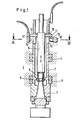
- Fig. 1 einen Axialschnitt durch eine Arbeitsspindel mit der erfindungsgemäßen Werkzeug-Spannvorrichtung;
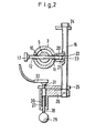
- Fig. 2 einen Schnitt A-B in Fig. l.
- Figure 1 is an axial section through a work spindle with the tool clamping device according to the invention.
- Fig. 2 shows a section AB in Fig. L.
Wie dargestellt, ist in einem Spindelstock 1 eine Arbeitsspindel 2 in Lagern 4 drehbar gelagert. In der Arbeitsspindel 2 ist eine Spanneinrichtung 5 zentral und mittels eines nicht dargestellten Antriebes längsverschiebbar angeordnet, die an ihrem in Fig. 1 unteren Ende Spannzungen 6 zum Erfassen eines Werkzeug-Steilkegels 7 aufweist. In der in Fig. 1 dargestellten Greifstellung stützen sich die Spannzungen 6 an der Schrägfläche eines konischen Ansatzes 8 im Inneren der Arbeitsspindel ab. Durch eine Axialverschiebung der Spanneinrichtung 5 in Fig. 1 nach unten erfolgt eine Aufspreizung der Spannzungen 6 und damit die Freigabe des Werkzeug-Steilkegels 7.As shown, a
Am oberen Ende der Spanneinrichtung 5 ist ein zylindrischer Querzapfen 10 befestigt, dessen beide vorstehenden Enden 11, 12 jeein achsparalleles Langloch 13, 14 in der Arbeitsspindel spielfrei durchragen und über den Spindelumfang vorstehen. In der in Fig. 1 dargestellten Position ist unter dem rechten Ende 11 des Querzapfens 10 ein Führungsglied 15 angeordnet, das radial vorstehend an einer im Spindelgehäuse quer zur Spindellängsachse verlaufenden Welle 16 befestigt ist. Durch eine Verdrehung der Welle um 90° kann das Führungsglied 15 aus der durchgezogen dargestellten Betriebsstellung in die gestrichelt dargestellte Außerbetriebsstellung bewegt werden.At the upper end of the
Der das Langloch 14 durchragende linke Endteil 12 des Querzapfens 10 stellt einen Schaltstift zur Betätigung eines Endschalters 17 dar. Dieser Endschalter ist so gegenüber dem Schaltstift 12 positioniert, daß er betätigt wird, sobald die Spannzange 5 einen vorbestimmten Verschiebeweg zurückgelegt hat und dadurch der Werkzeug-Steilkegel 7 von den Spannzungen 6 freigegeben ist. Durch diese Betätigung des Endschalters 17 wird über die numerische Steuerung der Werkzeugwechsler mit seinen Greiforganen in Betrieb gesetzt, um den Werkzeug-Steilkegel 7 aus der Spindel 2 abzuziehen.The
. Wie in Fig. 2 dargestellt, besteht das Führungsglied 15 aus zwei zueinander parallelen Platten 20, 21 mit zueinander weisenden Führungsflächen 22, 23 für den zylindrischen Querzapfen 10. Die Welle 16 ist beidendig in Zwischenwänden 24, 25 des Spindelstocks 1 gelagert-und trägt an ihrem unteren Ende eine Kurbel 26, in derem abgewinkelten Schenkel 27 der Bolzen 28 eines Handgriffs 29 gegen die Kraft einer Feder 30 längsverschiebbar gelagert ist. Der Bolzen 28 endet in einem Schaltstift 31, welcher eine Bohrung in der Wand 25 durchragt und das Schaltglied für einen elektrischen Schalter 32 darstellt. Durch Zurückziehen des Bolzens 28 mittels des Handgriffes 29 gegen die Kraft der Feder 30 wird der Schalter 32 mittels des Schaltstiftes 31 betätigt und nach Herausziehen des Schaltstiftes 31 aus der Bohrung in der Wand 35 wird die Kurbel 26 freigegeben und kann von Hand verdreht werden, wodurch das Führungsglied aus der in Fig. 1 in Vollinien dargestellten Betriebsstellung in seine gestrichelt eingezeichnete Außerbetriebsstellung verschwenkt wird. Damit wird die Wirkung der Indexiervorrichtung aufgehoben und der Werkzeug-Steilkegel kann in jeder beliebigen Drehstellung z. B. von Hand gewechselt werden.. As shown in Fig. 2, the
Die Erfindung ist nicht auf das dargestellte Ausführungsbeispiel beschränkt. So können beispielsweise statt des durchgehenden Querzapfens 10 gesonderte Glieder zum Indexieren einerseits und zur Betätigung des Endschalters 17 andererseits vorgesehen werden. Ferner sind auch andere Betätigungseinrichtungen für die Spannzungen 6 möglich.The invention is not restricted to the exemplary embodiment shown. For example, instead of the continuous
Claims (5)
dadurch gekennzeichnet,
daß die Indexiervorrichtung einen an der Spanneinrichtung (5) befestigten Querzapfen (10) aufweist, der ein axiales Langloch (13) in der Arbeitsspindel (2) spielfrei durchragt und der bei einer Längsbewegung der Spanneinrichtung zwischen zwei Führungsflächen (22, 23) geführt ist.1.Tool clamping device for milling and drilling machines in particular, consisting of a clamping device with clamping tongues arranged longitudinally displaceably centrally in the work spindle, a rotary position transmitter for presetting the work spindle into its tool change position and an indexing device for the work spindle,
characterized,
that the indexing device has a cross pin (10) attached to the tensioning device (5), which projects through an axial slot (13) in the work spindle (2) without play and which is guided between two guide surfaces (22, 23) during a longitudinal movement of the tensioning device.
daß die Führungsflächen (22, 23) an einem Führungsglied (15) ausgebildet sind, das im Spindelstock (1) in die Bahn des Querzapfens (11) bewegbar angeordnet ist.2. Clamping device according to claim 1, characterized in
that the guide surfaces (22, 23) are formed on a guide member (15) which is movably arranged in the headstock (1) in the path of the cross pin (11).
daß das Führungsglied (15) zwei Platten (20, 21) aufweist, die an einer Welle (16) befestigt sind.3. Clamping device according to claim 2, characterized in
that the guide member (15) has two plates (20, 21) which are attached to a shaft (16).
daß an der Spanneinrichtung (5) ein Schaltstift (12) befestigt ist, der ein Langloch (14) in der Spindelhülse (3) durchragt und bei Werkzeugfreigabe einen mit der numerischen Steuerung gekoppelten Endschalter (17)betätigt.4. Clamping device according to one of claims 1 to 3, characterized in
that a switching pin (12) is attached to the clamping device (5), which extends through an elongated hole (14) in the spindle sleeve (3) and actuates a limit switch (17) coupled to the numerical control when the tool is released.
daß dem Führungsglied (15) eine Verriegelungsvorrichtung (28 bis 31) und ein elektrische Schalter (32) zugeordnet sind.5. Clamping device according to one of claims 1 to 4, characterized in
that the guide member (15) is associated with a locking device (28 to 31) and an electrical switch (32).
Applications Claiming Priority (2)
| Application Number | Priority Date | Filing Date | Title |
|---|---|---|---|
| DE19843447595 DE3447595A1 (en) | 1984-12-28 | 1984-12-28 | TOOL CLAMPING DEVICE, IN PARTICULAR MILLING AND DRILLING MACHINES |
| DE3447595 | 1984-12-28 |
Publications (3)
| Publication Number | Publication Date |
|---|---|
| EP0185889A2 true EP0185889A2 (en) | 1986-07-02 |
| EP0185889A3 EP0185889A3 (en) | 1988-01-27 |
| EP0185889B1 EP0185889B1 (en) | 1990-02-28 |
Family
ID=6254004
Family Applications (1)
| Application Number | Title | Priority Date | Filing Date |
|---|---|---|---|
| EP85113669A Expired - Lifetime EP0185889B1 (en) | 1984-12-28 | 1985-10-28 | Tool clamping device in particular for milling and boring machines |
Country Status (4)
| Country | Link |
|---|---|
| US (1) | US4705440A (en) |
| EP (1) | EP0185889B1 (en) |
| JP (1) | JPS61209843A (en) |
| DE (1) | DE3447595A1 (en) |
Cited By (4)
| Publication number | Priority date | Publication date | Assignee | Title |
|---|---|---|---|---|
| EP0480283A1 (en) * | 1990-10-09 | 1992-04-15 | Chiron-Werke GmbH & Co. KG | Machine tool |
| EP0681880A1 (en) * | 1994-04-30 | 1995-11-15 | Chiron-Werke GmbH & Co. KG | Machine tool |
| ITVI20110158A1 (en) * | 2011-06-20 | 2012-12-21 | Vem S P A | SYSTEM FOR THE IDENTIFICATION OF A CORRECT POSITION OF ATTACHING / RELEASING A TOOL, IN PARTICULAR FOR A MULTIFUNCTION OPERATING MACHINE |
| CN112893944A (en) * | 2021-01-15 | 2021-06-04 | 江南工业集团有限公司 | Commutator segment milling separation clamping device and operation method |
Families Citing this family (7)
| Publication number | Priority date | Publication date | Assignee | Title |
|---|---|---|---|---|
| JPH01140903A (en) * | 1987-11-24 | 1989-06-02 | Okuma Mach Works Ltd | Pulling-up device for tool or the like |
| DE4415466A1 (en) * | 1994-05-03 | 1995-11-09 | Messma Kelch Robot Gmbh Maschi | Pick-up and tensioning device, in particular for measuring and setting devices |
| JPH10277803A (en) * | 1997-03-28 | 1998-10-20 | Sodick Co Ltd | Spindle and spindle device of machine tool |
| DE102005048800A1 (en) * | 2005-09-13 | 2007-03-22 | Röhm Gmbh | Method for operating an actuating unit and device for carrying out the method |
| CN105817652B (en) * | 2016-05-24 | 2019-01-04 | 东莞市优超精密技术有限公司 | It can automatic tool changer ultrasonic wave electro spindle |
| CN107932151B (en) * | 2017-12-29 | 2024-03-08 | 重庆四通机械科技有限公司 | Shaft sleeve turning tool |
| DE102021206591A1 (en) | 2021-06-25 | 2022-12-29 | Kadia Produktion Gmbh + Co. | Process for changing tools on a machine tool and machine tool |
Citations (8)
| Publication number | Priority date | Publication date | Assignee | Title |
|---|---|---|---|---|
| DE2304206A1 (en) * | 1972-03-27 | 1973-10-18 | Houdaille Industries Inc | MACHINE TOOL |
| US4008518A (en) * | 1974-08-30 | 1977-02-22 | Textron, Inc. | Machine tools |
| US4019246A (en) * | 1974-10-23 | 1977-04-26 | Toyoda Koki Kabushiki Kaisha | Machine tool with automatic tool changer |
| DE2650758A1 (en) * | 1975-11-06 | 1977-05-18 | Houdaille Industries Inc | DEVICE ON A MACHINE TOOL WITH A TOOL CARRYING SPINDLE |
| DE1427008B2 (en) * | 1960-04-27 | 1977-12-15 | The New Britain Machine Co, New Britain, Conn. (V.St.A.) | MACHINE TOOLS, IN PARTICULAR DRILLING AND MILLING MILL |
| EP0032029A2 (en) * | 1979-12-31 | 1981-07-15 | Fanuc Ltd. | A control system for stopping a spindle at a predetermined rotational position |
| EP0104008A1 (en) * | 1982-09-03 | 1984-03-28 | Hurco Manufacturing Company, Inc. | Machine tool spindle stop and tool release mechanism |
| DE3404497A1 (en) * | 1984-02-09 | 1985-08-29 | Kelch Gmbh + Co Werkzeugmaschinenfabrik, 7060 Schorndorf | Method and apparatus for the rotary alignment of a machine tool work spindle |
Family Cites Families (5)
| Publication number | Priority date | Publication date | Assignee | Title |
|---|---|---|---|---|
| DD117828A1 (en) * | 1975-02-19 | 1976-02-05 | ||
| US4242019A (en) * | 1978-02-23 | 1980-12-30 | Roch Gerald V | Milling machine |
| JPS5939137B2 (en) * | 1980-09-12 | 1984-09-21 | 輝雄 福田 | Waste disposal equipment for beds, wheelchairs, etc. used by seriously ill people, physically disabled people, bedridden elderly people, etc. |
| JPS5939137U (en) * | 1982-09-06 | 1984-03-13 | 豊田工機株式会社 | Spindle tool attachment/detachment device |
| JPS5986903U (en) * | 1982-11-30 | 1984-06-12 | 東洋精器株式会社 | Chuck device in tool presetter |
-
1984
- 1984-12-28 DE DE19843447595 patent/DE3447595A1/en active Granted
-
1985
- 1985-10-28 EP EP85113669A patent/EP0185889B1/en not_active Expired - Lifetime
- 1985-12-18 US US06/810,511 patent/US4705440A/en not_active Expired - Fee Related
- 1985-12-20 JP JP60287608A patent/JPS61209843A/en active Granted
Patent Citations (8)
| Publication number | Priority date | Publication date | Assignee | Title |
|---|---|---|---|---|
| DE1427008B2 (en) * | 1960-04-27 | 1977-12-15 | The New Britain Machine Co, New Britain, Conn. (V.St.A.) | MACHINE TOOLS, IN PARTICULAR DRILLING AND MILLING MILL |
| DE2304206A1 (en) * | 1972-03-27 | 1973-10-18 | Houdaille Industries Inc | MACHINE TOOL |
| US4008518A (en) * | 1974-08-30 | 1977-02-22 | Textron, Inc. | Machine tools |
| US4019246A (en) * | 1974-10-23 | 1977-04-26 | Toyoda Koki Kabushiki Kaisha | Machine tool with automatic tool changer |
| DE2650758A1 (en) * | 1975-11-06 | 1977-05-18 | Houdaille Industries Inc | DEVICE ON A MACHINE TOOL WITH A TOOL CARRYING SPINDLE |
| EP0032029A2 (en) * | 1979-12-31 | 1981-07-15 | Fanuc Ltd. | A control system for stopping a spindle at a predetermined rotational position |
| EP0104008A1 (en) * | 1982-09-03 | 1984-03-28 | Hurco Manufacturing Company, Inc. | Machine tool spindle stop and tool release mechanism |
| DE3404497A1 (en) * | 1984-02-09 | 1985-08-29 | Kelch Gmbh + Co Werkzeugmaschinenfabrik, 7060 Schorndorf | Method and apparatus for the rotary alignment of a machine tool work spindle |
Cited By (6)
| Publication number | Priority date | Publication date | Assignee | Title |
|---|---|---|---|---|
| EP0480283A1 (en) * | 1990-10-09 | 1992-04-15 | Chiron-Werke GmbH & Co. KG | Machine tool |
| EP0681880A1 (en) * | 1994-04-30 | 1995-11-15 | Chiron-Werke GmbH & Co. KG | Machine tool |
| ITVI20110158A1 (en) * | 2011-06-20 | 2012-12-21 | Vem S P A | SYSTEM FOR THE IDENTIFICATION OF A CORRECT POSITION OF ATTACHING / RELEASING A TOOL, IN PARTICULAR FOR A MULTIFUNCTION OPERATING MACHINE |
| EP2537630A1 (en) * | 2011-06-20 | 2012-12-26 | VEM S.p.A. | System for the identification of the proper position of attachment or release of a tool |
| CN112893944A (en) * | 2021-01-15 | 2021-06-04 | 江南工业集团有限公司 | Commutator segment milling separation clamping device and operation method |
| CN112893944B (en) * | 2021-01-15 | 2022-03-29 | 江南工业集团有限公司 | Commutator segment milling separation clamping device and operation method |
Also Published As
| Publication number | Publication date |
|---|---|
| US4705440A (en) | 1987-11-10 |
| DE3447595A1 (en) | 1986-07-03 |
| EP0185889A3 (en) | 1988-01-27 |
| DE3447595C2 (en) | 1988-06-16 |
| JPS61209843A (en) | 1986-09-18 |
| EP0185889B1 (en) | 1990-02-28 |
| JPH0230808B2 (en) | 1990-07-10 |
Similar Documents
| Publication | Publication Date | Title |
|---|---|---|
| EP0043584B1 (en) | Automated multiple-station machine tool | |
| EP0054838B1 (en) | Facing and boring head and machine-tool for retaining this tool | |
| EP0307691B1 (en) | Tool changer for universal milling and boring machine | |
| DE1777019C3 (en) | Machine tool with a tool changing device | |
| DE19605156B4 (en) | Tool head for use in machine tools and machine tool with such a tool head | |
| EP0158182A2 (en) | Milling and boring head for a machine tool | |
| EP0213399A2 (en) | Tool changer | |
| EP0125434A2 (en) | Machine tool with a tool changing device | |
| EP0185889B1 (en) | Tool clamping device in particular for milling and boring machines | |
| EP0261312A2 (en) | Angle positioning device for a working spindle | |
| DE10354441B4 (en) | Tool changing device | |
| WO1985005300A1 (en) | Feed and guide device for a material bar in a lathe | |
| DE3634018C2 (en) | ||
| DE2156153C3 (en) | Spindle arrangement for machine tools | |
| DE3106800A1 (en) | Spindle carrier of machining centres | |
| DE938577C (en) | Machine tool, in particular for machining, with interchangeable tools and with devices for setting the work values adapted to the tools | |
| DE3246994C2 (en) | ||
| DE19504370A1 (en) | Multi-spindle lathe | |
| WO2012130444A1 (en) | Socket alignment device for a bar loading magazine and method | |
| DD143054A1 (en) | DEVICE FOR ANGLE DRILLING TOOLS FOR TOOLING MACHINES | |
| DE2512794B2 (en) | Device for thread cutting | |
| DE2946307C2 (en) | Portable device for thread cutting or the like. | |
| EP0280862A2 (en) | Guiding device for long reach drill | |
| EP0123290A2 (en) | Device for turning extended cylindrical or slightly conical work pieces | |
| DE102019123119B3 (en) | Mobile device for machining a workpiece |
Legal Events
| Date | Code | Title | Description |
|---|---|---|---|
| PUAI | Public reference made under article 153(3) epc to a published international application that has entered the european phase |
Free format text: ORIGINAL CODE: 0009012 |
|
| AK | Designated contracting states |
Kind code of ref document: A2 Designated state(s): CH FR IT LI |
|
| RAP1 | Party data changed (applicant data changed or rights of an application transferred) |
Owner name: MAHO AKTIENGESELLSCHAFT |
|
| PUAL | Search report despatched |
Free format text: ORIGINAL CODE: 0009013 |
|
| AK | Designated contracting states |
Kind code of ref document: A3 Designated state(s): CH FR IT LI |
|
| 17P | Request for examination filed |
Effective date: 19880204 |
|
| 17Q | First examination report despatched |
Effective date: 19890117 |
|
| GRAA | (expected) grant |
Free format text: ORIGINAL CODE: 0009210 |
|
| AK | Designated contracting states |
Kind code of ref document: B1 Designated state(s): CH FR IT LI |
|
| ITF | It: translation for a ep patent filed |
Owner name: JACOBACCI & PERANI S.P.A. |
|
| ET | Fr: translation filed | ||
| PLBE | No opposition filed within time limit |
Free format text: ORIGINAL CODE: 0009261 |
|
| STAA | Information on the status of an ep patent application or granted ep patent |
Free format text: STATUS: NO OPPOSITION FILED WITHIN TIME LIMIT |
|
| 26N | No opposition filed | ||
| ITTA | It: last paid annual fee | ||
| REG | Reference to a national code |
Ref country code: CH Ref legal event code: NV Representative=s name: MICHELI & CIE Ref country code: CH Ref legal event code: PFA Free format text: MAHO AKTIENGESELLSCHAFT TRANSFER- DECKEL MAHO AKTIENGESELLSCHAFT Ref country code: CH Ref legal event code: PUE Owner name: GILDEMEISTER AKTIENGESELLSCHAFT TRANSFER- DECKEL M |
|
| REG | Reference to a national code |
Ref country code: FR Ref legal event code: CD |
|
| REG | Reference to a national code |
Ref country code: FR Ref legal event code: TP |
|
| PGFP | Annual fee paid to national office [announced via postgrant information from national office to epo] |
Ref country code: FR Payment date: 19981009 Year of fee payment: 14 |
|
| PGFP | Annual fee paid to national office [announced via postgrant information from national office to epo] |
Ref country code: CH Payment date: 19990114 Year of fee payment: 14 |
|
| PG25 | Lapsed in a contracting state [announced via postgrant information from national office to epo] |
Ref country code: CH Free format text: LAPSE BECAUSE OF NON-PAYMENT OF DUE FEES Effective date: 19991031 Ref country code: LI Free format text: LAPSE BECAUSE OF NON-PAYMENT OF DUE FEES Effective date: 19991031 |
|
| REG | Reference to a national code |
Ref country code: CH Ref legal event code: PL |
|
| PG25 | Lapsed in a contracting state [announced via postgrant information from national office to epo] |
Ref country code: FR Free format text: LAPSE BECAUSE OF NON-PAYMENT OF DUE FEES Effective date: 20000630 |
|
| REG | Reference to a national code |
Ref country code: FR Ref legal event code: ST |