EP0032029A2 - A control system for stopping a spindle at a predetermined rotational position - Google Patents
A control system for stopping a spindle at a predetermined rotational position Download PDFInfo
- Publication number
- EP0032029A2 EP0032029A2 EP80304614A EP80304614A EP0032029A2 EP 0032029 A2 EP0032029 A2 EP 0032029A2 EP 80304614 A EP80304614 A EP 80304614A EP 80304614 A EP80304614 A EP 80304614A EP 0032029 A2 EP0032029 A2 EP 0032029A2
- Authority
- EP
- European Patent Office
- Prior art keywords
- spindle
- rotational position
- signal
- predetermined rotational
- specified point
- Prior art date
- Legal status (The legal status is an assumption and is not a legal conclusion. Google has not performed a legal analysis and makes no representation as to the accuracy of the status listed.)
- Granted
Links
Images


Classifications
-
- B—PERFORMING OPERATIONS; TRANSPORTING
- B23—MACHINE TOOLS; METAL-WORKING NOT OTHERWISE PROVIDED FOR
- B23B—TURNING; BORING
- B23B1/00—Methods for turning or working essentially requiring the use of turning-machines; Use of auxiliary equipment in connection with such methods
-
- B—PERFORMING OPERATIONS; TRANSPORTING
- B23—MACHINE TOOLS; METAL-WORKING NOT OTHERWISE PROVIDED FOR
- B23Q—DETAILS, COMPONENTS, OR ACCESSORIES FOR MACHINE TOOLS, e.g. ARRANGEMENTS FOR COPYING OR CONTROLLING; MACHINE TOOLS IN GENERAL CHARACTERISED BY THE CONSTRUCTION OF PARTICULAR DETAILS OR COMPONENTS; COMBINATIONS OR ASSOCIATIONS OF METAL-WORKING MACHINES, NOT DIRECTED TO A PARTICULAR RESULT
- B23Q15/00—Automatic control or regulation of feed movement, cutting velocity or position of tool or work
- B23Q15/20—Automatic control or regulation of feed movement, cutting velocity or position of tool or work before or after the tool acts upon the workpiece
- B23Q15/22—Control or regulation of position of tool or workpiece
- B23Q15/26—Control or regulation of position of tool or workpiece of angular position
-
- Y—GENERAL TAGGING OF NEW TECHNOLOGICAL DEVELOPMENTS; GENERAL TAGGING OF CROSS-SECTIONAL TECHNOLOGIES SPANNING OVER SEVERAL SECTIONS OF THE IPC; TECHNICAL SUBJECTS COVERED BY FORMER USPC CROSS-REFERENCE ART COLLECTIONS [XRACs] AND DIGESTS
- Y10—TECHNICAL SUBJECTS COVERED BY FORMER USPC
- Y10T—TECHNICAL SUBJECTS COVERED BY FORMER US CLASSIFICATION
- Y10T82/00—Turning
- Y10T82/25—Lathe
- Y10T82/2502—Lathe with program control
-
- Y—GENERAL TAGGING OF NEW TECHNOLOGICAL DEVELOPMENTS; GENERAL TAGGING OF CROSS-SECTIONAL TECHNOLOGIES SPANNING OVER SEVERAL SECTIONS OF THE IPC; TECHNICAL SUBJECTS COVERED BY FORMER USPC CROSS-REFERENCE ART COLLECTIONS [XRACs] AND DIGESTS
- Y10—TECHNICAL SUBJECTS COVERED BY FORMER USPC
- Y10T—TECHNICAL SUBJECTS COVERED BY FORMER US CLASSIFICATION
- Y10T82/00—Turning
- Y10T82/25—Lathe
- Y10T82/2552—Headstock
- Y10T82/2561—Spindle or work angler
Landscapes
- Engineering & Computer Science (AREA)
- Mechanical Engineering (AREA)
- Automatic Control Of Machine Tools (AREA)
- Stopping Of Electric Motors (AREA)
- Control Of Position Or Direction (AREA)
Abstract
Description
- This invention relates to a control system for stopping a spindle at a predetermined rotational position.
- Some machine tools which are known in the art have an automatic tool changing function which allows machining to be performed while a variety of tools mounted on the machine are interchanged automatically.' The tool changing operation proceeds as follows. First, a magazine holding a number of tools is revolved to bring a vacant tool holding portion of the magazine into position directly above a spindle mechanism. The spindle mechanism, which is grasping an old tool to be exchanged for a new one, is then projected forwardly, after which the magazine positioned above the spindle mechanism is lowered to permit the.old tool to be received and grasped by the vacant tool holding portion of the magazine. The spindle mechanism is then retracted so that the old tool separates from the spindle, thereby transferring the old tool to the magazine. Next, the magazine is revolved to bring a desired new tool into position in front of the spindle, and the spindle mechanism is projected forwardly to allow the spindle to receive and to grasp the new tool. Finally the magazine is raised away from the spindle to complete the tool change operation.
- It is required in the tool change mechanism of the foregoing type that a prescribed part of the spindle, suchas a key member, be stopped accurately at the correct rotational position in order to permit the fitting portions of the spindle and tool to mate with each other smoothly. More specifically, a key is mounted on the spindle and a keyway is formed in the tool in order to mate with the key. The smooth mating of the spindle and tool requires that the spindle be positioned and stopped to provide the'correct alignment of key and keyway. Meeting the above requirement necessitates a high spindle positioning accuracy of from ±0.1 to ±0.2 degrees in terms of the angle of rotation of the spindle.
- The conventional automatic tool change mechanisms are provided with photoelectric detectors or with limit switch mechanisms which detect the rotational position of the spindle key in order to facilitate the smooth mating of the spindle and tools. The arrangement is such that the spindle is brought to a stop at the prescribed position by the application of a mechanical brake which is actuated in response to a signal from the key position detecting means.
- The foregoing apparatus employs a stopping mechanism that experiences wear. with a long period of use since the mechanism relies upon a mechanical pin or brake or the like. Such wear, particularly of a brake shoe or pin, makes it progressively more difficult to stop the spindle at the predetermined position, and the result 'is that the automatic changing of tools cannot proceed smoothly.
- Accordingly, there is a need for a control system 'which is capable of stopping a spindle at a predetermined rotational position with a high degree of accuracy by purely electrical means, without relying upon a mechanical pin or mechanical brake mechanism to stop the spindle in performing an automatic tool change operation.
- On the other hand, numerically controlled machine tools are being applied increasingly to the boring of such workpieces as automobile engine boxes. Such boring work requires the use of thicker boring bars or cutters in view of preventing chatter by increasing rigidity. There are cases, however, where the use of thicker diametered boring bars cannot be avoided, as in the case of boring a hole whose dimensions are such that the thicker boring bars cannot be inserted. This point will be elaborated on in the following description of a boring machine tool.
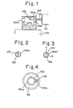
- Fig. 1 is an illustrative view of a boring machine tool in simplified form. Provided are a
headstock 101, aboring bar 102, and acutting tool 103. Aworkpiece 104, which is carried on a table 105, includesholes boring bar 102, and a hollow portion 104b. In the boring machine tool of this type, thecutting tool 103 is inserted into the hollow portion 104b of theworkpiece 104 through either theinsertion hole holes boring bar 102 of a small diameter, as shown in Fig. 2, in order to prevent thecutting tool 103 from contacting the periphery of thehole 104a when the boring bar is inserted into and withdrawn from the interior of the workpiece. The small diameter boring bar results in chatter during machining so that a high degree of accuracy cannot be achieved. - Proposed methods of solving the above problem are shown in Figs. 3 and 4, wherein arrangements are adopted that permits the utilization of a
boring bar 102 of a larger diameter. In accordance with the method of Fig. 3, the center of theboring bar 102 is offset from the center of thehole 104a along the Y-axis when the boring bar is inserted and withdrawn, thecutting tool 103 being positioned so as to coincide with the Y-axis. It should be noted, however, that the choice of the Y-axis here is illustrative only. In accordance with the method of Fig. 4, a cuttingtool insertion notch 104c is formed in theworkpiece 104 so as to communicate with theinsertion hole 104a, and thecutting tool 103 is so positioned as to coincide with thenotch 104c when the boring bar is inserted and withdrawn. Both. methods depicted in Figs. 3 and 4 reduce chatter by allowing the use of aboring bar 102 of a larger diameter. When the cutting tool is inserted into the workpiece and when its rotation is stopped after a machining operation, both of the above methods require that the spindle of the machine tool be stopped accurately at a predetermined rotational position which is the positive Y-axis in the arrangement of Fig. 3 and the position of the cuttingtool insertion slot 104c in the arrangement of Fig. 4. In other words, in order to eliminate chatter and effect a rigid machining operation by employing a boring bar of a larger diameter, a control system is required through which the spindle mounting the boring bar can be stopped at a predetermined rotational position. - The foregoing control of spindle stopping position is thus required for both automatic tool change and machining operations. And, in general, since the positions at which the spindle is stopped'differ in both cases, there is an additional requirement that the spindle be stoppable at either of two rotational positions.
- According to the present invention there is provided a control system for stopping a spindle at a predetermined rotational position, for driving a spindle in such a manner that a positional deviation between the present rotational position of a specified point on the spindle and a predetermined rotational position at which the specified point is to be stopped, is reduced to zero, thereby to stop the specified point on the spindle at the predetermined rotational position, which control system comprises:
- i a first rotational position sensor associated with a first specified point on the spindle, for producing a rotational position deviation signal when a tool is to be inserted into and withdrawn from a workpiece at the time of a boring or other machining operation;
- a second rotational position sensor associated with a second specified point on the spindle, for producing a rotational position deviation signal at the time of a tool change or other operation;
- changeover means for selectively switching between the rotational position deviation signal from said first rotational position sensor and the rotational position deviation signal from said second rotational position sensor; and
- an orientation control circuit for receiving the rotational position deviation signal selected by said changeover means thereby to control the spindle in such a manner that the spindle is stopped at.an appropriate predetermined rotational position.
- Accordingly, it is possible to provide a control system for stopping a spindle at a predetermined rotational position, by which a spindle can be stopped at first and second rotational positions at the time of an automatic tool change operation and boring operation, respectively.
- It may be possible to provide that the spindle can be stopped at first and second rotational positions with a high degree of accuracy.
- Embodiments of the invention may utilize two novel position sensors that detect rotational position without relying upon physical contact.
- A preferred embodiment of the present invention may provide a structurally simple and inexpensive control system for stopping a spindle at a predetermined rotational position, in which a spindle is stopped at first and second rotational positions by a very simple arrangement which includes first and second magnetic sensors mounted on the spindle, a single switching circuit and an orientation circuit.
- a preferred embodiment of Other features and advantages of/the invention will be apparent from the following description taken in conjunction with the accompanying drawings.
-
- Fig. 1 is an illustrative view showing a boring machine tool in simplified form;
- Fig. 2 is an illustrative view showing the positional relationships among a cutting tool, a boring bar and a hole, located in a workpiece, for receiving the cutting tool and boring bar;
- Figs. 3 and 4 are illustrative views showing methods of inserting a boring bar into a hole located in a workpiece;
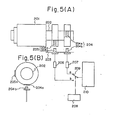
- Fig. 5A is an illustrative view which is useful in describing a control system, shown in simplified form, for stopping a spindle at a predetermined rotational position in accordance with the present invention;
- Fig. 5B is an illustrative view which is useful in describing the disposition of position sensors;
- Fig. 6 is a block diagram which is useful in describing a control circuit for stopping a spindle at a predetermined rotational position in accordance with the present invention;
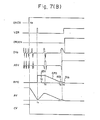
- Fig. 7 is a waveform diagram of signals associated with the block diagram of Fig. 6;
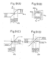
- Figs. 8 and 9 are illustrative views which are useful in describing the structure and operation of magnetic sensors in accordance with the present invention;
- Fig. 10 is a circuit diagram showing a position deviation signal generating circuit in detail; and
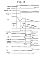
- Fig. 11 is a timing chart associated with the cir- cuit of Fig. 10.
- Referring now to Figs. 5A and 5B, first and
second position sensors magnetic bodies magnetic.bodies spindle 202 accommodated by aspindle mechanism 201, and thesensing portions 204b, 205b are fixedly secured to a mechanically stationary portion.203 of the machine tool. Thefirst position sensor 204 is employed in stopping thespindle 202 at a predetermined rotational position at the time of a boring operation, and thesecond position sensor 205 at the time of an automatic tool change operation. Since the rotational position at which the spindle is : stopped during the automatic tool change is fixed, themagnetic body 205a of the second position sensor 205.is fixedly secured to thespindle 202 permanently at the predetermined location. In the case of the boring operation, however, the rotational position at which thespindle 202 is to be stopped differs depending upon the shape and location of the insertion hole formed in the workpiece. For this reason themagnetic body 204a of thefirst position sensor 204 is mounted on thespindle 202 in such a manner that it can be set at any desired location.Amplifiers second position sensors control circuit 208 which instructs achangeover switch 209 to switch between the output of theamplifier 206 and the output of theamplifier 207, the selected output being delivered to anorientation control circuit 210 which will be described later. - When a cutting tool for boring work is inserted into or withdrawn from a workpiece, the
changeover switch 209 is connected to the contact a to deliver the amplified output signal from thefirst position sensor 204 to theorientation control circuit 210 which executes an orientation control operation in accordance with the received signal in a manner that will be described later. The orientation control operation stops thespindle 202 in such a manner that themagnetic body 204a attached thereto comes to rest at a position facing the sensing portion 204b. On the other hand, when a tool is to be changed, thechangeover switch 209 is connected.to the contact b to deliver the amplified output of thesecond position sensor 205 to theorientation control circuit 210 which executes an orientation control operation in accordance with the received signal to stop thespindle 202 in such a manner that themagnetic body 205a fixedly secured thereto comes to rest at a position facing thesensing portion 205b. - Reference will now be had to Figs. 6, 7, 8 and 9.
- Provided are a
speed command circuit 301 for producing a speed command CV, and an orientation command circuit 302 for producing an orientation command ORCM. Aspeed control circuit 303 includes anadder 303a, aphase compensating circuit 303b connected to the output of the adder, a voltage-to-phase converter 303c connected to the output of the phase compensating circuit, and athyristor converter 303d connected to the output of theconverter 303c. Theadder 303a is adapted to deliver a difference voltage, representative of a speed deviation, between the command speed CV and the actual speed AV of aDC motor 304, during a speed control operation, and to deliver a difference voltage between a rotational position deviation RPD and the actual speed AV during a positional control operation. Thephase compensating circuit 303b subjects the output voltage of theadder 303a to a phase compensation by advancing or retarding its phase. The voltage-to-phase converter 303c controls the firing angle of each thyristor in thethyristor converter 303d in accordance with the output voltage of thephase compensating circuit 303b. Thethyristor converter 303d operates in accordance with the controlled firing angles of its thyristors to vary the value of the voltage applied to theDC motor 304, thereby to regulate the speed at which the motor rotates. As theDC motor 304 rotates, atachometer 305 generates a voltage in accordance with the motor speed. The rotational motion of theDC motor 304 is transmitted through agear train 309 or timing belt to aspindle 307 which corresponds to thespindle 202 shown in Fig. 5. Thespindle 307 is coupled to aspindle mechanism 306 which mounts atool 308.Magnetic sensors 310, 310' correspond to theposition sensors magnetic body 310a, asensing portion 310b and anelectrical circuit 310c, as illustrated in Fig. 8. - The front and plan views of the position sensor, namely Figs. 8A and 8B, show the
magnetic body 310a mounted on thespindle 307. Themagnetic body 310a is mounted on thespindle 307 at an angular position thereof corresponding to the specified point which is to be stopped at the predetermined rotational position. Themagnetic body 310a, as shown in Fig. 8C, hasmagnets case 31 in such a manner that the intensity of the magnetic field changes from S to N in the direction of spindle rotation, i.e., in the direction of the arrow. Thesensing portion 310b is mounted on the mechanically stationary portion of the machine so as to confront themagnetic body 310a, and includes three saturable reactors SRA1, SRA2, SRA3 provided in acase 34 and aligned in the direction of spindle rotation, as illustrated in Fig. 8C. Coils Ll, L2 are wound on the core CR of each saturable reactor, as depicted in Fig. 8D. The coils L1, L2 on each core CR are so wound as to have opposing polarities. The coils on each core share a common contact TA to which a high-frequency signal is applied, and signals which are in accordance with the rotational position of themagnetic body 310a are obtained from the terminals TB, TC of respective coils. - Shown in Fig. 8E are voltage waveforms obtained from sensing circuits, which will be described later, provided for corresponding ones of the saturable reactors SRA1 through SRA3 when the
magnetic body 310a andsensing portion 310b have the positional relationship shown in Fig. 8C. Specifically, DV1, DV2, DV3 denote the voltage waveforms from the sensing circuits corresponding to the respective saturable reactors SRA1, SRA2, SRA3. Each of these waveforms has a value of zero volts when the center line of the corresponding saturable reactor SRA1, SRA2, or SRA3 coincides with the center line of themagnetic body 310a. At such time the waveform is positive on one side of the zero value and negative on the other side; that is, it completely crosses the zero level. The voltage waveform ASV is obtained by adding together the voltage DV1 and a voltage which results by subjecting the voltage DV3 to a phase shift of 180 degrees. A sensing circuit corresponding to one of the saturable reactors, namely the reactor SRA1, is shown in detail in Fig. 8F. The sensing circuit, which is provided in theelectrical circuit 310c, includes a pulse oscillator OSC for generating a 100KHz high-frequency pulse signal HFP, an isolating transformer ITR, and half-wave rectifiers HWR1, HWR2.. The saturable reactor SRA1 is excited by the high-frequency pulse signal HFP through the intermediary of the isolating transformer ITR. As a result, the output voltage DV1, shown in Fig. 8E, will be obtained across the output terminals a, b of the circuit shown in Fig. 8E, this output voltage being approximately proportional to the external magnetic field Hext whose strength varies in. accordance with the rotational position of themagnetic body 310a. - The action of a voltage waveform DV1 obtained across the terminals a, b will now be described with reference to Fig. 9 in connection with the reactor SRA1 on the left side of Fig. 8C. When the
magnetic body 310a is remote from the saturable reactor SRA1 so that the external magnetic field acting upon reactor SRA1 has a value of zero, the high-frequency pulse signal HFP acts about the vertical zero line of the reactor B-H curve as its center, as shown in Fig. 9A. As a result, the number of lines of flux cutting the coils L1, L2 are equal, so that the output voltages from the terminals TB, TC are equal in amplitude but displaced in phase by 180°. It should be noted that since these voltages are rectified by the respective half-wave rectifiers HWR1, HWR2, the potentials at the terminals a, b are equal, so that the voltage across a, b is zero. Now, as themagnetic body 310a approaches the saturable reactor SRA1, the external magnetic field Hext being generated by the magnetic body begins to act upon the reactor SRA1. If we let h1 denote the field generated by the high-frequency pulse signal HFP, a flux in accordance with hℓ - Hext will cut the coil Ll, as shown in Fig. 9C, and a flux in accordance with hℓ + Hext will cut the coil L2. If this is expressed by a B-H curve, the high-frequency pulse signal HFP will act about the line -Hext as its center with respect to coil L1, as shown in Fig. 4C, and about the line +Hext with respect to coil L2, as depicted in Fig. 9D. Therefore the negatively directed flux which cuts the coil Ll causes saturation of the core so that there is a smaller amount of variation, whereas the negatively directed flux which crosses the coil L2 does not cause saturation so that there is a greater amount of variation. In view of the fact that the induced voltage e takes on the value
magnetic body 310a continues to rotate. This completes the description of theposition detector 310. - Returning now to Fig. 6, a
changeover switch 311 is changed over by a command from a control circuit 311'. Anorientation control circuit 312, corresponding to theorientation control circuit 210 shown in Fig. 5, includes a rotational position deviationsignal generating circuit 312a which produces a rotational position deviation signal RPD of a voltage value in accordance with a rotational position deviation, an orientation completion signal ORDEN, and a zero speed signal VZR which assumes a logical value of "1" when the rotational speed of the spindle falls to zero, and aloop changeover circuit 312b for actuating a loop changeover switch 313b on the basis of the zero speed signal VZR when so instructed by the orientation command ORCM from the orientation command circuit 302. The generation of the rotational position deviation signal RPD will now be described briefly in connection with the waveforms of Fig. 7A, although the rotational position deviationsignal generating circuit 312a will be described in detail later. - The rotational position deviation
signal generating circuit 312a receives, from the,changeover switch 311, the detection voltage DV2 (which is utilized as a fine, as opposed to a coarse, rotational position deviation signal when the spindle is in the vicinity of the predetermined rotational position) corresponding to the saturable reactor SRA2 which is the centrally disposed one inposition sensor 310 or 310', and an approach signal ASV which is obtained by adding the detection voltage DV1 and the voltage which results by shifting the phase of the detection voltage DV3 by 180°, the detection voltages DV1, DV3 corresponding to the saturable reactors SRA1, SRA3 on either side of the reactor SRA2. The signal ASV indicates that the spindle has reached an area in the environs of . the predetermined rotational position. The signal AV . indicative of the actual speed of the motor enters the rotational position deviationsignal generating circuit 312a from thetachometer 305 and is integrated within the circuit by an integration circuit which is not shown The output (equivalent to the amount of spindle rotation) of the integration circuit is subtracted from an initially set voltage ISV. Thus, the signal AV is converted into a coarse rotational position deviation signal CPD. The voltage value vi of the voltage ISV has been set so as to be equal to a rotational position deviation voltage which corresponds to one revolution (360°) of the spindle. - Further, the rotational position deviation
signal generating circuit 312a forms a bias signal BIS, retained within the circuit, having an amplitude which is equivalent to the peak value of the fine rotational position deviation signal DV2. - When the speed command CV falls to zero in accordance with an orientation command ORCM from the orientation command circuit 302, the rotational speed of the spindle diminishes and eventually (at time tl) falls to zero (zero speed signal VZR goes to logic "1"). When this occurs, the rotational position deviation
signal generating circuit 312a produces the initially set voltage ISV from the time that the zero speed signal VZR goes to logic "1" until the time t2 at which the spindle initially reaches the predetermined rotational position. Thereafter, as the spindle continues to rotate and themagnetic body 310a (the predetermined part of the spindle) approaches the predetermined rotational position for the second time, the coarse position deviation signal CPD is produced until themagnetic body 310a draws near to the area NCP (defined between -01 and +01) in the environs of the predetermined rotational position, that is, until it arrives at the position -02. Furthermore, the bias signal BIS is produced until the abovementioned area NCP is reached. The fine position deviation signal DV2 is generated after themagnetic body 310a has reached and then entered the area NCP in the environs of the predetermined rotational position. The result of these operations is the rotational position deviation signal RPD which is shown in Fig. 7A. It should be noted that the bias signal waveform BIS may be excluded from the signal RPD by setting 02 equal to O1. - Reference will now be had to Fig. 7B to describe the operation of the control circuit, shown in Fig. 6, for stopping the spindle at a predetermined rotational position. It will be assumed that the
changeover switch 311 is connected to the contacts a so that the rotational position deviationsignal generating circuit 312a is receiving the output of the second magnetic sensor 310' which is used in a tool change operation as mentioned above. - During rotation of the spindle the
changeover switch 313 is connected to the a side in Fig. 6, thereby forming a speed control loop. More specifically, the adder 313a receives the speed command signal CV from thespeed command circuit 301 and the average speed signal AV from thetachometer 305, and responds by delivering a rotational speed deviation voltage. The voltage-to-phase converter 303c controls the firing angle of the thyristors in thethyristor circuit 303d in accordance with the speed deviation voltage, thethyristor circuit 303d thereby regulating the voltage applied to theDC motor 304. As a result, the actual speed AV of themotor 304 is regulated to bring it into coincidence with the command speed CV. Thereafter the speed control loop regulates the speed of the motor so as to bring the speed deviation toward zero, the spindle rotating while maintaining a constant speed deviation. - When the machining work is completed under these conditions, a numerical control device instructs the orientation command circuit 302 to apply the orientation command signal ORCM to the
loop changeover circuit 312b at the time t0. At the same time the orientation command ORCM is applied to thespeed command circuit 301, so that the speed command CV drops to zero. The actual speed AV consequently decreases the reaches zero at time tl. When this occurs, the zero speed signal VZR is generated within the position deviationsignal generating circuit 312a, and causes theloop changeover circuit 312b to change over theswitch 313 to the side b, so that circuit operation now changes from speed control position control. In response to the zero.,speed signal VZR, the position deviationsignal generating circuit 312a produces first the initially set voltage ISV having the voltage value Vi. In response to this signal the spindle begins to rotate again so that the signal AV indicative of the actual speed rises to assume the value Vi. As themagnetic body 310a of the second magnetic sensor 310' continues to rotate (Fig. 8) and reaches the predetermined rotational position for the first time (t2), the rotational position deviationsignal generating circuit 312a begins generating the coarse position deviation signal CPD. As the spindle continues to rotate and themagnetic body 310a approaches the area NCP (Fig. 7a) in the environs of the predetermined rotational position (time t3), the position deviationsignal generating circuit 312a produces the bias signal BIS. Then, when themagnetic body 310a arrives at the abovementioned area NCP (time t4), generation of the fine position deviation signal DV2 starts. When the signal DV2 has decreased to zero, namely when themagnetic body 310a on the predetermined part of the spindle is directly confronting the central saturable reactor SAR2, the spindle steps rotating. This completes positioning control of the spindle. - When the cutting tool is to be inserted into or withdrawn from a workpiece during a boring operation, the
changeover switch 311 is switched to the side b by a control signal from the control circuit 311'. Thereafter, an orientation operation identical with that described above in connection with the tool change is executed to stop the spindle at the predetermined rotational position that allows insertion or withdrawal of the cutting tool. - The structure of the rotational position deviation
signal generating circuit 312a is shown in Fig. 10, and the associated timing chart is illustrated in Fig. 11. Portions in Fig. 10 identical with those of Fig. 6 are denoted by like reference characters and are not described again in order to avoid prolixity. - In Fig. 10, a
circuit 401 is provided to form the initially set voltage ISV and the bias signal BIS, to integrate the actual speed voltage signal AV, and to subtract the output voltage, resulting from the integration operation, from the initially set voltage ISV. Specifically, a changeover switch SW is switched over to either a +15 volt side or a -15 volt side in accordance with the direction of spindle rotation. If the spindle is rotating in the forward direction, the connection is to the -15 volt side. This voltage is divided by resistors rl, r2, and a capacitor C is charged through an amplifier AMP1, a resistor r4 and a switch S9, the voltage charged in the capacitor becoming the value Vi of the initially set voltage ISV. If the actual speed signal AV enters thecircuit 401 through a switch S8 or S7 after the switch Sg has been opened, the capacitor C discharges at the time constant RC since the voltage value of the actual speed signal AV is lower than Vi, and the coarse.position deviation signal CPD, obtained due to the subtraction of the output voltage namely the result of integrating the actual speed signal AV, from the initially set voltage ISV, appears at the output of the amplifier AMP2, the amplifier AMP2, resistor R and capacitor C forming an integration circuit. If the switches S9, S10 are closed after the voltage of the signal CPD reaches a specified value Vj, thecircuit 401 acts as an amplifier, and the bias signal BIS at the specified level Vj is obtained at the output of the amplifier AMP2. - In other words, in accordance with the particular combination and timing of the opening and closing operation of the switches S7 through S10, first the initially set voltage ISV is delivered, then the coarse position deviation signal CPD, and finally the bias signal BIS.
-
Numerals DC motor 304 and thespindle 307 are set low (reduction ratio high), and to set the gain low when the gears are set high (reduction ratio low), that is, to set the gain low in comparison to the gain for the high reduction ratio. More specifically, when the reduction ratio is high, switches S7, S2 are closed to raise the gain, and when the reduction ratio is low, switches Sg, S3 are closed to lower the gain. This eliminates spindle hunting and overshoot when stopping the spindle at the predetermined rotational position, and permits the spindle stopping operation to be completed in less time regardless of the scale of the reduction ratio. - Denoted at 404 is a well-known-absolute value circuit which takes the absolute value of the output from the
circuit 401. Acomparator 405 detects whether or not the coarse position deviation signal CPD has fallen below a predetermined level, and produces a signal NRPS which indicates that the predetermined portion (themagnetic body 310a of either of thesensors 310, 310') has'drawn near the area (-02 to +02 in Fig. 7A) in the environs of the predetermined rotational stopping position. The signal NRPS closes the switches S9, S10. - A
gain adjustment circuit 406 adjusts the gain in accordance with the gap between either of themagnetic bodies 310a and the correspondingsensing portions 310b, and produces the detection signal DV2 (the fine position deviation voltage) having a prescribed slope. Aslicer circuit 407 slices the approach signal ASV at a predetermined level and produces a signal LS which indicates that either of the magnetic bodies has reached the area NCP (Fig. 7A) in the environs of the predetermined rotational position. The signal LS opens the switches S5, S6 and closes switch S4. As a result, the fine position deviation signal DV2 is delivered as the deviation signal. - A forward-
reverse changeover circuit 408 has its switch S5 closed to deliver the output of theabsolute value circuit 404 in a case where the spindle is controlled by.rotating it in the forward direction, and its switch S6 closed to deliver the output of the absolute value circuit 404-after it has been inverted by the amplifier 408a, in a case where the spindle is controlled by rotating it in the reverse direction. An "in-position"signal generating circuit 409, comprising a comparator, monitors the fine position deviation signal DV2 and generates the in-position signal INPOS when the spindle is within the range of the predetermined rotational position. The signal INPOS is applied to an orientation completion signal generating circuit which will be described later. -
Comparators waveform synthesizing circuit 412 delivers either the fine position deviation signal or the coarse position deviation signal in accordance with the open or closed state of the switch S4, S5 or S6. Aspeed detection circuit 413 receives the voltage AV indicative of the actual speed of the spindle and generates the zero speed signal VZR when AV falls to zero. An orientation completion signal generating circuit 414 receiges the in-position signal INPOS, the zero speed signal VZR and the orientation command signal ORCM, and takes the logical product of these signals, thereby producing the orientation completion signal ORDEN when INPOS, VZR and ORCM are all at logical "1". - In summary, if the orientation command ORCM goes to logical "1" at time to, the command speed CV drops to zero volts, so that the actual speed AV, decreases with AV dropping to zero volts and the zero speed signal VZR going to logical "1". When this occurs the
loop changeover switch 313 is switched over to the side b, one of the switches S21 S3 closes in accordance with the low/high setting of the gears, and one of the switches S5, S6 closes in accordance with the direction, either forward or reverse, of spindle rotation. This forms a position control loop, with the initially set voltage ISV being delivered from thechangeover switch 313. It should be noted that the switch Sg is closed, and that switches S7, S8, S10 are open. The DC motor 304 shown in Fig. 6 begins rotating again so that the spindle is rotated and reaches the predetermined rotational position the first time (i.e., the signal LS is a "1", and the in-position signal INPOS is a "1"). Hence, at time t2, switch S9 is opened and one of the switches S7, 58 is closed in accordance with the low/high setting of the gears. Therefore the coarse position deviation signal CPD is obtained from thechangeover switch 313. Thereafter, as the actual speed AV and the position deviation decrease and the spindle approaches the area in the environs of the predetermined rotational position (time t3), thecomparator 405 issues the signal NRPS (logical "1"), whereby the switches S9 and S10 are closed. As a result, the bias signal BIS of the prescribed level is delivered from thechangeover switch 313. As the spindle continues to rotate at a slower speed and reaches the area NCP in the environs of the predetermined rotational position (time t4), the signal LS goes to the "1" level, switches S5, S6 are opened, and switch S4 is closed. Hence, the fine position deviation signal DV2 is delivered from thechangeover switch 313. When themagnetic body 310a (the predetermined point on the spindle) comes within range of the predetermined rotational position, the in-position signal INPOS is generated. This is followed by the actual speed of the spindle falling to zero, whereupon the zero speed-signal VZR returns to logical "1". This completes the control operation for stopping the spindle at the predetermined rotational position, the orientation completion signal ORDEN being delivered from the orientation completion signal generating circuit 414. - In the foregoing it was described that the
changeover switch 313 is switched over to the side b when the actual speed of the spindle reaches zero. Howeverm this changeover can be performed when the actual speed reaches a predetermined speed. - In accordance with the preferred embodiment of the present invention as described above, a single control circuit for stopping the spindle at a predetermined rotational position is provided, and two position sensors, one for a tool change operation and one for a boring operation, are mounted on the spindle. Switching between these sensors in a suitable manner allows the spindle to be stopped with a high degree of precision at a predetermined rotational position when tools are to be changed, and at another predetermined rotational position when boring work is to be carried out. The apparatus can be simplified and reduced in cost since the single control circuit can be used to stop the spindle at the predetermined positions for both the tool change and boring operations.
- Although the present invention has been described in its preferred form with a certain degree of particularity, it is obvious that many modifications and variations are possible in the light of the above teachings.. It is therefore to be understood-that within the scope of the appended claims, the invention may be practiced otherwise than as specifically described.
- A control system for stopping a
spindle 202 at a predetermined rotational position, for driving aspindle 202 in such a manner that a positional deviation signal between the present rotational position of a specified point on thespindle 202 and a predetermined rotational position at which the specified point is to be stopped, is reduced to zero, thereby to stop the specified point on the spindle at the predetermined rotational position. First and second rotational posit-.ion sensors spindle 202 at first and second specified points thereof, the position at which at least the firstrotational position sensor 204 is attached being adjustable. Further provided are changeover means 209 and anorientation control circuit 210. Thefirst position sensor 204 produces a rotational position deviation signal when a tool is inserted into and withdrawn from a workpiece at the time of a boring operation,and thesecond position sensor 205 produces a rotational position deviation signal when tools are changed. These deviation signals are applied to theorientation control circuit 210 selectively by changeover means 209. As a result, theorientation control circuit 210 controls the rotation of thespindle 202 so as to reduce to zero the difference between an average speed signal, which conforms to the actual rotational speed of thespindle 202, and each of the deviation signals, whereby a specified point on thespindle 202 is stopped at a predetermined rotational position.
Claims (6)
Applications Claiming Priority (2)
| Application Number | Priority Date | Filing Date | Title |
|---|---|---|---|
| JP172685/79 | 1979-12-31 | ||
| JP17268579A JPS56102451A (en) | 1979-12-31 | 1979-12-31 | Control system for stopping main spindle at definite position |
Publications (3)
| Publication Number | Publication Date |
|---|---|
| EP0032029A2 true EP0032029A2 (en) | 1981-07-15 |
| EP0032029A3 EP0032029A3 (en) | 1982-02-10 |
| EP0032029B1 EP0032029B1 (en) | 1986-05-14 |
Family
ID=15946455
Family Applications (1)
| Application Number | Title | Priority Date | Filing Date |
|---|---|---|---|
| EP80304614A Expired EP0032029B1 (en) | 1979-12-31 | 1980-12-19 | A control system for stopping a spindle at a predetermined rotational position |
Country Status (5)
| Country | Link |
|---|---|
| US (1) | US4359676A (en) |
| EP (1) | EP0032029B1 (en) |
| JP (1) | JPS56102451A (en) |
| DE (1) | DE3071608D1 (en) |
| SU (1) | SU1308185A3 (en) |
Cited By (1)
| Publication number | Priority date | Publication date | Assignee | Title |
|---|---|---|---|---|
| EP0185889A2 (en) * | 1984-12-28 | 1986-07-02 | MAHO Aktiengesellschaft | Tool clamping device in particular for milling and boring machines |
Families Citing this family (16)
| Publication number | Priority date | Publication date | Assignee | Title |
|---|---|---|---|---|
| US4495448A (en) * | 1981-11-06 | 1985-01-22 | Dumbeck Robert F | Means and method of sensing motor rotation speed from stray escaping flux |
| DE3245790A1 (en) * | 1982-12-10 | 1984-06-14 | Oerlikon-Boehringer GmbH, 7320 Göppingen | DRIVEN SETTING STICK FOR LATHE |
| DE3323502C1 (en) * | 1983-06-30 | 1985-01-03 | Index-Werke Kg Hahn & Tessky, 7300 Esslingen | Automatic turret lathe |
| JP2510980B2 (en) * | 1985-10-21 | 1996-06-26 | 株式会社安川電機 | Screw cutting control method |
| US4746848A (en) * | 1985-12-13 | 1988-05-24 | Tsudakoma Corp. | Weft yarn feeding device for a loom |
| JPH0729252B2 (en) * | 1986-01-17 | 1995-04-05 | 東芝機械株式会社 | Spindle positioning device |
| EP0374259B1 (en) * | 1988-04-19 | 1995-10-18 | Nakamura-Tome Precision Ind. Co., Ltd. | Two opposed main shaft type cnc lathe |
| JP2692274B2 (en) * | 1989-06-22 | 1997-12-17 | 三菱電機株式会社 | Spindle position / speed control device |
| US5093610A (en) * | 1990-02-12 | 1992-03-03 | Abb Robotics Inc. | Apparatus for absolute position measurement |
| JPH04294406A (en) * | 1991-03-22 | 1992-10-19 | Kobe Steel Ltd | Rotational position detecting device for robot |
| IL138755A0 (en) * | 1998-04-03 | 2001-10-31 | N T Naum Technologies Ltd | Automatic adjustable power chuck system and method |
| SE528392C2 (en) | 2005-03-11 | 2006-10-31 | Atlas Copco Rock Drills Ab | Sensor installation in a gearbox for positioning |
| TWI347075B (en) * | 2007-06-29 | 2011-08-11 | Delta Electronics Inc | Motor control device and method thereof |
| DE102007032416A1 (en) * | 2007-07-12 | 2009-01-15 | Aradex Ag | Method for actuating a clamping device and clamping system for carrying out the method |
| CN102922000B (en) * | 2012-10-23 | 2015-10-07 | 潍柴动力股份有限公司 | A kind of horizontal boring machine and spindle locating mechanism thereof |
| JP7323758B2 (en) * | 2018-11-22 | 2023-08-09 | スター精密株式会社 | lathe |
Citations (11)
| Publication number | Priority date | Publication date | Assignee | Title |
|---|---|---|---|---|
| US2902890A (en) * | 1953-11-27 | 1959-09-08 | Charles F Staples | Boring machines |
| GB1027607A (en) * | 1963-11-18 | 1966-04-27 | Ass Elect Ind | Arrangements for controlling angular displacement |
| GB1062246A (en) * | 1964-03-04 | 1967-03-22 | Hartman Metal Fabricators Inc | Positioning apparatus |
| GB1154141A (en) * | 1966-01-10 | 1969-06-04 | Nat Res Dev | Improvements in and relating to Electro-Motive Apparatus. |
| FR2147009A1 (en) * | 1971-07-23 | 1973-03-09 | Robert Jean | |
| US3824891A (en) * | 1973-05-11 | 1974-07-23 | Litton Industrial Products | Machine tool |
| FR2213713A5 (en) * | 1973-01-05 | 1974-08-02 | Automatisme Tech Electro Contr | |
| FR2255142A1 (en) * | 1973-12-21 | 1975-07-18 | Sagem | Tool carrier drive for programmed machine tool - has carrier and spindle alternately locked and released |
| EP0012619A2 (en) * | 1978-12-16 | 1980-06-25 | Fanuc Ltd. | Machine tool drive motor control system |
| GB2039079A (en) * | 1978-12-28 | 1980-07-30 | Tlv Co Ltd | Electric motor driving-gear |
| EP0028079A2 (en) * | 1979-10-09 | 1981-05-06 | Fanuc Ltd. | Control system for stopping spindle at predetermined rotational position |
Family Cites Families (8)
| Publication number | Priority date | Publication date | Assignee | Title |
|---|---|---|---|---|
| US2537269A (en) * | 1948-03-18 | 1951-01-09 | Ex Cell O Corp | Spindle positioning device |
| US2753502A (en) * | 1952-12-02 | 1956-07-03 | Bardons And Oliver Inc | Electric motor control for spindle positioner |
| US2790280A (en) * | 1955-03-21 | 1957-04-30 | Cincinnati Milling Machine Co | Spindle positioning mechanism |
| DE1170506B (en) * | 1962-03-06 | 1964-05-21 | Siemens Ag | Device for controlling or regulating longitudinal or rotary movements |
| JPS5274972A (en) * | 1975-12-19 | 1977-06-23 | Kubota Ltd | Device for stopping cutting tool at predetermined position in boring machine |
| JPS5916291B2 (en) * | 1977-04-28 | 1984-04-14 | ファナック株式会社 | Spindle control method |
| JPS54143985A (en) * | 1978-04-28 | 1979-11-09 | Fanuc Ltd | Spindle control method |
| US4227134A (en) * | 1979-01-05 | 1980-10-07 | Acme-Cleveland Corporation | Spindle rotator |
-
1979
- 1979-12-31 JP JP17268579A patent/JPS56102451A/en active Granted
-
1980
- 1980-12-12 US US06/215,631 patent/US4359676A/en not_active Expired - Lifetime
- 1980-12-19 DE DE8080304614T patent/DE3071608D1/en not_active Expired
- 1980-12-19 EP EP80304614A patent/EP0032029B1/en not_active Expired
- 1980-12-31 SU SU803222704A patent/SU1308185A3/en active
Patent Citations (11)
| Publication number | Priority date | Publication date | Assignee | Title |
|---|---|---|---|---|
| US2902890A (en) * | 1953-11-27 | 1959-09-08 | Charles F Staples | Boring machines |
| GB1027607A (en) * | 1963-11-18 | 1966-04-27 | Ass Elect Ind | Arrangements for controlling angular displacement |
| GB1062246A (en) * | 1964-03-04 | 1967-03-22 | Hartman Metal Fabricators Inc | Positioning apparatus |
| GB1154141A (en) * | 1966-01-10 | 1969-06-04 | Nat Res Dev | Improvements in and relating to Electro-Motive Apparatus. |
| FR2147009A1 (en) * | 1971-07-23 | 1973-03-09 | Robert Jean | |
| FR2213713A5 (en) * | 1973-01-05 | 1974-08-02 | Automatisme Tech Electro Contr | |
| US3824891A (en) * | 1973-05-11 | 1974-07-23 | Litton Industrial Products | Machine tool |
| FR2255142A1 (en) * | 1973-12-21 | 1975-07-18 | Sagem | Tool carrier drive for programmed machine tool - has carrier and spindle alternately locked and released |
| EP0012619A2 (en) * | 1978-12-16 | 1980-06-25 | Fanuc Ltd. | Machine tool drive motor control system |
| GB2039079A (en) * | 1978-12-28 | 1980-07-30 | Tlv Co Ltd | Electric motor driving-gear |
| EP0028079A2 (en) * | 1979-10-09 | 1981-05-06 | Fanuc Ltd. | Control system for stopping spindle at predetermined rotational position |
Cited By (2)
| Publication number | Priority date | Publication date | Assignee | Title |
|---|---|---|---|---|
| EP0185889A2 (en) * | 1984-12-28 | 1986-07-02 | MAHO Aktiengesellschaft | Tool clamping device in particular for milling and boring machines |
| EP0185889A3 (en) * | 1984-12-28 | 1988-01-27 | Maho Aktiengesellschaft | Tool clamping device in particular for milling and boring machines |
Also Published As
| Publication number | Publication date |
|---|---|
| SU1308185A3 (en) | 1987-04-30 |
| EP0032029A3 (en) | 1982-02-10 |
| JPS6140497B2 (en) | 1986-09-09 |
| DE3071608D1 (en) | 1986-06-19 |
| JPS56102451A (en) | 1981-08-15 |
| EP0032029B1 (en) | 1986-05-14 |
| US4359676A (en) | 1982-11-16 |
Similar Documents
| Publication | Publication Date | Title |
|---|---|---|
| EP0032029B1 (en) | A control system for stopping a spindle at a predetermined rotational position | |
| US4345192A (en) | Control system for stopping spindle at predetermined rotational position | |
| US4450393A (en) | Spindle orientation control apparatus | |
| US4451185A (en) | Boring tool holder with probes for measuring bore | |
| US4581808A (en) | Adjustable machining system and implement therefore | |
| US4400118A (en) | Machine tool with bore diameter measuring apparatus and tool position compensating apparatus | |
| EP0047853B1 (en) | Machine tool with tool position compensating apparatus and contact detecting apparatus | |
| US4195250A (en) | Automatic measuring and tool position compensating system for a numerically controlled machine tool | |
| EP0032045B1 (en) | Control system for stopping spindle at predetermined rotational position | |
| US5105135A (en) | Feedback controller for NC controlled machine tools | |
| US5231335A (en) | Double spindle synchronous driving apparatus | |
| EP0032301A2 (en) | A rotary arrangement comprising a control system for stopping a spindle at a predetermined rotational position | |
| US4347470A (en) | Spindle orientation control apparatus | |
| US5239479A (en) | Process for determining the presence or the dimensions or the correct positioning of a workpiece on a machine tool | |
| US4342950A (en) | Spindle rotation control system | |
| EP0032312B1 (en) | Control system for stopping spindle at predetermined rotational position | |
| US4386407A (en) | Lathe control system | |
| US4750104A (en) | Method of and apparatus for tracking position error control | |
| KR890002791B1 (en) | System for stopping main spindle at commended position | |
| SU793364A3 (en) | System for tool position control | |
| US4403181A (en) | Control system for stopping spindle at predetermined rotational position | |
| KR830001055B1 (en) | Spindle exact stop control device | |
| KR830001054B1 (en) | Spindle exact position control device | |
| KR830001765B1 (en) | Spindle exact stop control device | |
| US4453313A (en) | Method and apparatus for precision turning |
Legal Events
| Date | Code | Title | Description |
|---|---|---|---|
| PUAI | Public reference made under article 153(3) epc to a published international application that has entered the european phase |
Free format text: ORIGINAL CODE: 0009012 |
|
| AK | Designated contracting states |
Designated state(s): DE FR GB |
|
| RBV | Designated contracting states (corrected) |
Designated state(s): DE FR GB NL SE |
|
| RBV | Designated contracting states (corrected) |
Designated state(s): DE FR GB |
|
| PUAL | Search report despatched |
Free format text: ORIGINAL CODE: 0009013 |
|
| RHK1 | Main classification (correction) |
Ipc: B23Q 15/26 |
|
| AK | Designated contracting states |
Designated state(s): DE FR GB |
|
| 17P | Request for examination filed |
Effective date: 19820709 |
|
| RAP1 | Party data changed (applicant data changed or rights of an application transferred) |
Owner name: FANUC LIMITED |
|
| RAP1 | Party data changed (applicant data changed or rights of an application transferred) |
Owner name: FANUC LTD |
|
| GRAA | (expected) grant |
Free format text: ORIGINAL CODE: 0009210 |
|
| AK | Designated contracting states |
Kind code of ref document: B1 Designated state(s): DE FR GB |
|
| REF | Corresponds to: |
Ref document number: 3071608 Country of ref document: DE Date of ref document: 19860619 |
|
| ET | Fr: translation filed | ||
| PLBE | No opposition filed within time limit |
Free format text: ORIGINAL CODE: 0009261 |
|
| STAA | Information on the status of an ep patent application or granted ep patent |
Free format text: STATUS: NO OPPOSITION FILED WITHIN TIME LIMIT |
|
| 26N | No opposition filed | ||
| PGFP | Annual fee paid to national office [announced via postgrant information from national office to epo] |
Ref country code: GB Payment date: 19901207 Year of fee payment: 11 |
|
| PGFP | Annual fee paid to national office [announced via postgrant information from national office to epo] |
Ref country code: FR Payment date: 19901210 Year of fee payment: 11 |
|
| PG25 | Lapsed in a contracting state [announced via postgrant information from national office to epo] |
Ref country code: GB Effective date: 19911219 |
|
| GBPC | Gb: european patent ceased through non-payment of renewal fee | ||
| PG25 | Lapsed in a contracting state [announced via postgrant information from national office to epo] |
Ref country code: FR Effective date: 19920831 |
|
| REG | Reference to a national code |
Ref country code: FR Ref legal event code: ST |
|
| PGFP | Annual fee paid to national office [announced via postgrant information from national office to epo] |
Ref country code: DE Payment date: 19971230 Year of fee payment: 18 |
|
| PG25 | Lapsed in a contracting state [announced via postgrant information from national office to epo] |
Ref country code: DE Free format text: LAPSE BECAUSE OF NON-PAYMENT OF DUE FEES Effective date: 19991001 |