EP0185753B1 - Dichtungssätze für die bohrung eines tauchkolbens - Google Patents
Dichtungssätze für die bohrung eines tauchkolbens Download PDFInfo
- Publication number
- EP0185753B1 EP0185753B1 EP85903495A EP85903495A EP0185753B1 EP 0185753 B1 EP0185753 B1 EP 0185753B1 EP 85903495 A EP85903495 A EP 85903495A EP 85903495 A EP85903495 A EP 85903495A EP 0185753 B1 EP0185753 B1 EP 0185753B1
- Authority
- EP
- European Patent Office
- Prior art keywords
- packing
- ring
- male
- front face
- rear face
- Prior art date
- Legal status (The legal status is an assumption and is not a legal conclusion. Google has not performed a legal analysis and makes no representation as to the accuracy of the status listed.)
- Expired - Lifetime
Links
Images
Classifications
-
- F—MECHANICAL ENGINEERING; LIGHTING; HEATING; WEAPONS; BLASTING
- F04—POSITIVE - DISPLACEMENT MACHINES FOR LIQUIDS; PUMPS FOR LIQUIDS OR ELASTIC FLUIDS
- F04B—POSITIVE-DISPLACEMENT MACHINES FOR LIQUIDS; PUMPS
- F04B53/00—Component parts, details or accessories not provided for in, or of interest apart from, groups F04B1/00 - F04B23/00 or F04B39/00 - F04B47/00
- F04B53/16—Casings; Cylinders; Cylinder liners or heads; Fluid connections
- F04B53/162—Adaptations of cylinders
- F04B53/164—Stoffing boxes
-
- F—MECHANICAL ENGINEERING; LIGHTING; HEATING; WEAPONS; BLASTING
- F16—ENGINEERING ELEMENTS AND UNITS; GENERAL MEASURES FOR PRODUCING AND MAINTAINING EFFECTIVE FUNCTIONING OF MACHINES OR INSTALLATIONS; THERMAL INSULATION IN GENERAL
- F16J—PISTONS; CYLINDERS; SEALINGS
- F16J15/00—Sealings
- F16J15/16—Sealings between relatively-moving surfaces
- F16J15/18—Sealings between relatively-moving surfaces with stuffing-boxes for elastic or plastic packings
- F16J15/182—Sealings between relatively-moving surfaces with stuffing-boxes for elastic or plastic packings with lubricating, cooling or draining means
- F16J15/183—Sealings between relatively-moving surfaces with stuffing-boxes for elastic or plastic packings with lubricating, cooling or draining means using a lantern ring
Definitions
- the invention relates to an improved packing assembly of the type used to prevent fluid leaks around a plunger.
- the packing assembly is used in plunger-type pumps.
- plunger-type pumps such as Triplex or Quintuplex pumps.
- plunger-type pumps such as Triplex or Quintuplex pumps.
- each plunger is pulled along the plunger bore away from the valve chamber.
- the plunger reverses direction and is pushed back along the bore toward the pump chamber, to displace incoming fluid through the outlet valves.
- Rings of packing material are installed in the plunger bore to prevent the incoming fluid from leaking past the plunger.
- Each of the packing rings in cross-section, is shaped like a chevron, and each ring has a central groove on the front side which functions as a hinge.
- the rear of each packing ring therefore, has a generally convex shape and the front face is of a generally concave shape.
- the bottom edge of each packing ring defines a lip which fits snugly against the plunger to provide the liquid-tight seal.
- the packing rings are set into the plunger bore in side-by-side relation.
- This structure is usually referred to as a single stack arrangement and generally includes about four packing rings.
- a metal (brass) female adaptor ring In front of the last packing ring in the stack is a metal (brass) female adaptor ring, a lubrication gland, a packing gland spacer, and a packing gland.
- the front face of the female adaptor ring has a generally concave shape, so that it can seat against the convex-shaped rear face of the first packing ring.
- Behind the first packing ring in the stack is a brass male adaptor ring.
- the rear face of the male adaptor ring has a generally convex shape, so that it can seat against the concave-shaped front face of the first packing ring.
- Another arrangement of the packing rings is referred to as a double stack.
- This arrangement usually consists of two packing rings, with a female adaptor ring positioned in front of the last packing ring in the stack, a male adaptor ring positioned behind the first ring in the stack, and a male-female adaptor ring positioned between the two packing rings.
- the adaptor rings keep the plunger concentric with the bore at the "fluid" end of the pump, and thus concentric with the packing rings.
- the adaptor rings also help to retain the integrity of the cross sectional dimensions of the packing rings.
- the adaptor rings now used in packing assemblies installed on plunger-type pumps have a serious defect which causes a wearing away of these rings, rather than increasing the life of the packing.
- the concave-shaped front faces on the female adaptor rings now available are formed with a 90 degree angle
- the convex-shaped rear faces on the male adaptor rings are formed with either a 90 degree angle or an angle of 115 degrees.
- the packing rings now available have rear faces formed with an angle of either 110 degrees or 120 degrees, and the front faces of these rings form an angle of 90 degrees.
- EP-A-0 102 756 describes a packer assembly with V-shaped packing rings (42, 44). The said rings are designed so as to leave no gap between their matching surfaces.
- the operating life of the packing is considerably improved by providing male and female adaptor rings with faces having an angle that precisely conforms to the corresponding angles formed on the faces of the various conventional packing rings now in use.
- the present invention particularly resides in a packing assembly which is installed in the plunger bore of a machine, such as a pump, to provide a fluid-tight seal for the machine, comprising: a packing gland secured at one end of the plunger bore; a packing gland spacer positioned adjacent to and in contact with the packing gland; a lubrication gland positioned adjacent to and in contact with the packing gland spacer; a separated stack of packing rings which includes at least two packing rings, each packing ring having a front face defining a concave shape, a rear face defining a convex shape, and a groove, defining a concave shape, at the center of the front face; a female adaptor ring positioned between the lubrication gland and the packing ring stack, the female adaptor ring has a front face with a concave shape, the concave shape defines an angle which conforms to the angle defined by the convex shape of the rear face of the last packing ring in the stack, such that the front face of the female adaptor
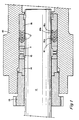
- Figure 1 is a front elevation view, mostly in section, of a packing assembly of this invention.
- the packing assembly is shown in its installed position in the plunger bore of a pump, with the packing rings being arranged in a unitary stack structure.
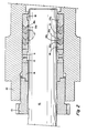
- Figure 2 is a front elevation view of another embodiment of a packing assembly of this invention, which is also installed in the plunger bore of a pump.
- the packing rings in this assembly are arranged in a separated stack structure.
- the drawing illustrates a packing assembly of this invention in which the packing rings are arranged in a unitary stack (referred to in prior packing assemblies as a "single stack").
- Numeral 10 refers generally to a housing member in a plunger-type pump having a bore 11.
- a slidable plunger 12 moves backwardly along bore 11 (to the left in Figure 1), to draw fluid into the pump chamber (not shown).
- plunger 12 reverses direction (to the right in Figure 1) to displace the fluid from the chamber.
- Betweeen the wall of bore 11 and the outside diameter of plunger 12 is a space, which is occupied by the packing assembly of the invention comprising a packing gland nut 13, which is threaded into the rear end of the bore 11.
- a packing gland spacer 14, having a shoulder at one end, is positioned against a corresponding shoulder on the packing gland nut.
- a lubrication gland 15 is positioned against the spacer 14 at one end.
- the opposite end of gland 15 engages the rear face of a female adaptor ring 16.
- the front face 16a of the female adaptor ring defines a concave shape.
- a unitary stack of packing rings 17 is provided in which the rear face of each packing ring 17, which faces toward the female adaptor ring 16, has a convex shape.
- each packing ring defines a concave shape.
- a concave-shaped groove positioned at the center of the front face. This central groove acts as a hinge to allow the packing ring to bend.
- the packing rings form a fluid-tight seal between the wall of bore 11 and the outside diameter of plunger 12.
- the unitary packing ring stack consists of four (4) rings. It will be understood, however, that the number of rings in the unitary stack can vary according to design calculations and other factors.
- the packing assembly includes a male adaptor ring 18 which is positioned in front of the first packing ring in the stack.
- the first packing ring has a front face 18a, which has a concave shape.
- the male adaptor ring 18 includes an integral rib 18b which is positioned at the center of the rear face and is of a generally convex shape.
- the packing rings 17 are fabricated with a front face which defines an angle of either 110 degrees or 120 degrees, and the rear face of each ring defines an angle of 90 degrees.
- the female adaptor ring 16 is fabricated such that the concave-shaped front face 16a forms an angle of 90 degrees. This enables the front face 16a of the female adaptor ring to seat firmly against the rear face of the last packing ring in the stack.
- the male adaptor ring 18 is fabricated such that the convex-shaped rear face 18a describes an angle of 110 degrees, or 120 degrees.
- the rib 18b is fabricated as an integral part of the rear face and has a convex shape which exactly conforms to the concave shape of the central groove (the hinge) in the first packing ring 17.
- the rib 18b on the male adaptor ring therefore, is a critical part of the present invention, which enables the ring to seat firmly against the front face of the first packing ring. This is a distinct advantage over conventional packing arrangements, which do not have a rib or similar member on the face of the adaptor rings.
- Figure 2 illustrates a packing assembly in which the packing rings are arranged in a separated stack structure (also referred to in the prior packing assemblies as a "double stack").
- the parts which make up this packing assembly are the same as those used in the packing assembly illustrated in Figure 1, except for a male-female adaptor ring 19, which is not required in the unitary packing ring stack.
- the parts of the packing assembly in Figure 2 which are identical to those shown in Figure 1 are designated with the same reference numerals.
- the female adaptor ring 16 is positioned between the lubrication gland 15 and the second packing ring 17, such that the concave-shaped front face 16a seats firmly against the convex-shaped rear face of the second packing ring.
- the male-female adaptor ring 19 is positioned between the two packing rings 17 which make up the separated stack.
- the male-female adaptor ring has a rear face 19a with a convex shape.
- At the center of the rear face is an integral rib member 19b, which has a generally convex shape.
- the male adaptor ring 18, is positioned in front of the first packing ring in the stack.
- the adaptor ring 18 also has a rear face 18a, with a convex shape, which includes a convex-shaped integral rib member 18b, located at the center of the face.
- the angle defined by the concave-shaped front face 16a of the female adaptor ring 16 is 90 degrees, so that the adaptor ring can seat firmly against the rear face of the second ring 17 in the separated stack.
- the convex-shaped rear face 19a of the male-female adaptor ring 19 defines an angle of 110 degrees, or 120 degrees, and the convex shape of rib 19b matches the central groove in the front face of the second packing ring, so that the adaptor ring can fit tightly against the packing ring.
- the angle on the concave-shaped front face 19c (like that of the adaptor ring 16), is 90 degrees, so that it conforms to the rear face of the first ring in the stack.
- the rear face 18a of the male adaptor ring 18 (like the rear face on adaptor 19) is fabricated with an angle of either 110 degrees or 120 degrees, so that it will fit snugly against the front face of the first packing ring.
- the adaptor rings are fabricated from brass, but other metal alloys or any material compatible with the environment in which the packing assembly must operate can be used.
- the unitary stack arrangement of the packing rings is usually employed in a packing assembly when the fluid pressure in the plunger bore is less than about 560 kg/cm2 (8,000 psi). When the pressure is between about 560 to 1400 kg/cm2 (about 8,000 to about 20,000 psi), the separated stack arrangement is preferred. Another factor to consider when choosing the separated stack arrangement, is that in this structure there is less packing material (the lips defined along the bottom edges of the packing rings) in contact with the sliding plunger. Since there is less packing material in contact with the moving plunger, the operating life of the packing is usually noticeably longer than is the case in the unitary stack arrangement.
Landscapes
- Engineering & Computer Science (AREA)
- General Engineering & Computer Science (AREA)
- Mechanical Engineering (AREA)
- Details Of Reciprocating Pumps (AREA)
- Sealing Devices (AREA)
Claims (2)
- Dichtpackungsanordnung, welche in die Plungerbohrung einer Maschine, beispielsweise einer Pumpe, eingesetzt wird, um eine fluiddichte Abdichtung für die Maschine zu bilden, umfassend: eine Pakkungsstopfbüchse (13), die an einem Ende der Plungerbohrung befestigt ist;
einen Abstandhalter (14) für die Packungsstopfbüchse, die bei und in Anlage an der Packungsstopfbüchse angeordnet ist;
eine bei und in Anlage an der Packungsstopfbüchse angeordnete Schmierbuchse;
einen getrennten Stapel Packungsringe (17) mit wenigstens zwei packungsringen, wobei jeder Pakkungsring eine Vorderseite mit einer konkaven Form, eine Rückseite mit einer konvexen Form und eine eine konkave Form aufweisende Nut in der Mitte der Vorderseite hat;
einen eingewölbten Adpaterring (16), welcher zwischen der Schmierbuchse und dem Packungsringstapel angeordnet ist, wobei der eingewölbte Adapterring eine Vorderseite mit konkaver Form hat und wobei diese konkave Form einen Winkel bildet, welcher dem von der konvexen Form der Rückseite des letzten Packungsringes im Stapel gebildeten Winkel angepaßt ist, so daß die Vorderseite des eingewölbten Adapterringes fest auf der Rückseite des letzten Packungsringes sitzt;
einen vorgewölbten Adapterring (18), welcher vor dem ersten Packungsring im Stapel angeordnet ist, wobei der vorgewölbte Adapterring eine Rückseite mit einer konvexen Form und ein damit integrales Rippenelement mit einer konvexen Form in der Mitte der Rückseite hat, wobei ferner die konvexe Form der Rückseite des vorgewölbten Adapterringes einen Winkel bildet, welcher exakt an den von der konkaven Form der Vorderseite des ersten Packungsringes gebildeten Winkel angepaßt ist, und wobei die konvexe Form des Rippenelementes exakt an die konkave Form der Nut in der Vorderseite des ersten Pakkungsringes angepaßt ist, so daß die Rückseite bzw. das integrale Rippenelement des vorgewölbten Adapterringes fest an der Vorderseite bzw. der Nut des ersten Packungsringes anliegen können, wobei die Dichtpackungsanordnung dadurch gekennzeichnet ist, daß die konkave Form der Vorderseite des eingewölbten Adapterringes (16) einen Winkel von etwa 90° bildet und daß die konvexe Form der Rückseite des vorgewölbten Adapterringes (18) einen Winkel von etwa 110° bis 120° bildet. - Packungsanordnung nach Anspruch 1, dadurch gekennzeichnet, daß sie einen vor- und eingewölbten Adapterring (19) hat, der zwischen zwei Packungsringen im Stapel angeordnet ist, wobei dieser vorund eingewölbte Adapterring eine Vorderseite und eine Rückseite hat, von denen die Rückseite eine konvexe Form sowie ein integrales Rippenelement mit einer konvexen Form in der Mitte der Rückseite, die Vorderseite jedoch eine konkave Form aufweist;
daß ferner die konvexe Form der Rückseite des vor- und eingewölbten Adapterringes einen Winkel bildet, welcher an den von der konkaven Form der Vorderseite des letzten Packungsringes im Stapel gebildeten Winkel angepaßt ist, und wobei die konvexe Form des Rippenelementes an die konkave Nut in der Vorderseite des letzten Packungsringes angepaßt ist, so daß die Rückseite bzw. das integrale Rippenelement des vor- und eingewölbten Adapterringes fest an der Vorderseite bzw. der Nut des letzten Packungsringes im Stapel anliegen können; daß die konkave Form der Vorderseite des vor- und eingewölbten Adapterringes einen Winkel bildet, welcher an den von der konvexen Form der Rückseite des ersten Packungsringes im Stapel gebildeten Winkel angepaßt ist, so daß die Vorderseite des vor- und eingewölbten Adapterringes fest an der Rückseite des ersten Packungsringes anliegen kann; und daß die konvexe Form der Rückseite des vor- und eingewölbten Adapterringes (19) einen Winkel von etwa 110° bis 120° bildet und die konkave Form der Vorderseite des vor- und eingewölbten Adapterringes einen Winkel von etwa 90° bildet.
Applications Claiming Priority (2)
| Application Number | Priority Date | Filing Date | Title |
|---|---|---|---|
| US620668 | 1984-06-14 | ||
| US06/620,668 US4572519A (en) | 1984-06-14 | 1984-06-14 | Packing assembly for use in a plunger bore |
Publications (3)
| Publication Number | Publication Date |
|---|---|
| EP0185753A1 EP0185753A1 (de) | 1986-07-02 |
| EP0185753A4 EP0185753A4 (de) | 1988-08-23 |
| EP0185753B1 true EP0185753B1 (de) | 1992-08-26 |
Family
ID=24486872
Family Applications (1)
| Application Number | Title | Priority Date | Filing Date |
|---|---|---|---|
| EP85903495A Expired - Lifetime EP0185753B1 (de) | 1984-06-14 | 1985-06-13 | Dichtungssätze für die bohrung eines tauchkolbens |
Country Status (5)
| Country | Link |
|---|---|
| US (1) | US4572519A (de) |
| EP (1) | EP0185753B1 (de) |
| CA (1) | CA1325025C (de) |
| NO (1) | NO860527L (de) |
| WO (1) | WO1986000119A1 (de) |
Cited By (2)
| Publication number | Priority date | Publication date | Assignee | Title |
|---|---|---|---|---|
| EP3546745A1 (de) * | 2018-03-28 | 2019-10-02 | Graco Minnesota Inc. | Verpackungsstapelträger für lack und andere fluidpumpen |
| US11458605B2 (en) | 2018-03-28 | 2022-10-04 | Graco Minnesota Inc. | Packing insertion tool for paint and other fluid pumps |
Families Citing this family (38)
| Publication number | Priority date | Publication date | Assignee | Title |
|---|---|---|---|---|
| US4576385A (en) * | 1984-12-12 | 1986-03-18 | Fmc Corporation | Fluid packing assembly with alternating diverse seal ring elements |
| US4844411A (en) * | 1988-03-14 | 1989-07-04 | Goddard Industries, Inc. | Valve |
| DE3834610A1 (de) * | 1988-10-11 | 1990-04-12 | Loegel Jun | Pumpenaggregat |
| US5338004A (en) * | 1990-07-16 | 1994-08-16 | Heil John S | Valve seal apparatus |
| US5549276A (en) * | 1991-01-24 | 1996-08-27 | E. I. Du Pont De Nemours And Company | Valve with perfluoroelastomer packing |
| US6212998B1 (en) | 1998-01-02 | 2001-04-10 | Graco Minnesota Inc. | Packings on pump rod |
| US6558141B2 (en) | 2001-04-12 | 2003-05-06 | Ingersoll-Rand Company | Packing assembly and reciprocating plunger pump incorporating same |
| AU2002306143A1 (en) * | 2001-06-12 | 2002-12-23 | Utex Industries, Inc. | Packing assembly for rotary drilling swivels |
| CA2353708C (en) * | 2001-07-24 | 2008-09-02 | Enviroseal Engineering Products, Ltd. | Bushing arrangement for seal cavity protection in rotating fluid equipment |
| DE10322352A1 (de) * | 2002-06-24 | 2004-01-22 | Volkswagen Ag | Elektrisch angetriebener Kompressor für eine Fahrzeug-Klimaanlage |
| US20070175627A1 (en) * | 2005-11-15 | 2007-08-02 | Pippert Frederick B | Stuffing box assembly and sealing assembly for use therein |
| JP5041896B2 (ja) * | 2006-12-06 | 2012-10-03 | 成雄 安藤 | 高圧シール装置 |
| EP1930633B1 (de) * | 2006-12-06 | 2010-10-06 | Shigeo Ando | Hochdruckabdichtungsvorrichtung |
| US8714560B2 (en) | 2009-04-28 | 2014-05-06 | Fisher Controls International Llc | Bidirectional seal assembly for use with valves |
| US8567753B1 (en) | 2011-07-18 | 2013-10-29 | Dennis W. Gilstad | Tunable valve assembly |
| US8210542B1 (en) | 2011-07-18 | 2012-07-03 | Gilstad Dennis W | Plunger seal ring |
| US8708306B2 (en) | 2011-08-03 | 2014-04-29 | Barbara C. Gilstad | Tunable valve assembly |
| US8720857B2 (en) | 2011-07-18 | 2014-05-13 | Dennis W. Gilstad | Tunable fluid end |
| US9027636B2 (en) | 2011-07-18 | 2015-05-12 | Dennis W. Gilstad | Tunable down-hole stimulation system |
| US8567754B1 (en) | 2011-07-18 | 2013-10-29 | Dennis W. Gilstad | Tunable valve assembly |
| US8944409B2 (en) | 2011-07-18 | 2015-02-03 | Dennis W. Gilstad | Tunable fluid end |
| US8403337B1 (en) | 2011-07-18 | 2013-03-26 | Barbara C. Gilstad | Multifunction ring |
| US8827244B2 (en) | 2011-07-18 | 2014-09-09 | Dennis W. Gilstad | Tunable fluid end |
| US8746654B2 (en) | 2011-07-18 | 2014-06-10 | Dennis W. Gilstad | Tunable fluid end |
| US8905376B2 (en) | 2011-07-18 | 2014-12-09 | Dennis W. Gilstad | Tunable check valve |
| US8276918B1 (en) | 2011-07-18 | 2012-10-02 | Gilstad Barbara C | Plunger seal ring |
| US8939200B1 (en) | 2011-07-18 | 2015-01-27 | Dennis W. Gilstad | Tunable hydraulic stimulator |
| US9080690B2 (en) | 2011-07-18 | 2015-07-14 | Dennis W. Gilstad | Tunable check valve |
| US8292301B1 (en) | 2011-07-18 | 2012-10-23 | Gilstad Dennis W | Multifunction ring |
| US8496224B1 (en) | 2011-07-18 | 2013-07-30 | Dennis W. Gilstad | Tunable valve assembly |
| US9239114B2 (en) * | 2012-11-05 | 2016-01-19 | Parker-Hannifin Corporation | Compressable sealing ring assembly |
| GB2515998B (en) * | 2013-05-01 | 2015-11-18 | Aes Eng Ltd | PFR bushing |
| US9169707B1 (en) | 2015-01-22 | 2015-10-27 | Dennis W. Gilstad | Tunable down-hole stimulation array |
| EP3967876B1 (de) * | 2016-02-05 | 2024-01-17 | Graco Minnesota Inc. | Fluidpumpenleckageumleitung |
| US11054036B2 (en) * | 2018-09-27 | 2021-07-06 | Seal-Ryt Corp. | Pillar lantern ring for a shaft sealing system |
| WO2020257426A1 (en) * | 2019-06-19 | 2020-12-24 | S.P.M. Flow Control, Inc. | Moveable seal point packing system |
| US20220403933A1 (en) * | 2021-06-16 | 2022-12-22 | Trelleborg Sealing Solutions Us, Inc. | Pressure equilibrating sealing system |
| US20240384795A1 (en) * | 2023-05-16 | 2024-11-21 | Kerr Machine Co. | Hybrid pressure seal |
Family Cites Families (8)
| Publication number | Priority date | Publication date | Assignee | Title |
|---|---|---|---|---|
| US2882104A (en) * | 1956-08-17 | 1959-04-14 | Harold A Guthans | Stern bearing packing glands |
| US3003797A (en) * | 1958-11-17 | 1961-10-10 | Gage Arthur Glover | Packing assembly |
| US3003793A (en) * | 1960-04-14 | 1961-10-10 | Edmund W Pitt | Longitudinally divided sleeved pipe coupling |
| US3586341A (en) * | 1969-06-16 | 1971-06-22 | Greene Tweed & Co Inc | Sealing construction |
| US3907307A (en) * | 1972-11-01 | 1975-09-23 | Exxon Production Research Co | Packing assembly |
| US4283062A (en) * | 1979-12-26 | 1981-08-11 | Cincinnati Milacron Inc. | Hydraulic injection molding machine stuffing box |
| US4384726A (en) * | 1981-11-02 | 1983-05-24 | Acf Industries, Incorporated | Expandable lubricating packing assembly for wellheads |
| US4440404A (en) * | 1982-08-09 | 1984-04-03 | Halliburton Company | Packing arrangement |
-
1984
- 1984-06-14 US US06/620,668 patent/US4572519A/en not_active Expired - Lifetime
-
1985
- 1985-06-13 EP EP85903495A patent/EP0185753B1/de not_active Expired - Lifetime
- 1985-06-13 WO PCT/US1985/001134 patent/WO1986000119A1/en not_active Ceased
- 1985-06-13 CA CA000483899A patent/CA1325025C/en not_active Expired - Fee Related
-
1986
- 1986-02-13 NO NO860527A patent/NO860527L/no unknown
Cited By (3)
| Publication number | Priority date | Publication date | Assignee | Title |
|---|---|---|---|---|
| EP3546745A1 (de) * | 2018-03-28 | 2019-10-02 | Graco Minnesota Inc. | Verpackungsstapelträger für lack und andere fluidpumpen |
| US10989306B2 (en) | 2018-03-28 | 2021-04-27 | Graco Minnesota Inc. | Packing stack carrier for paint and other fluid pumps |
| US11458605B2 (en) | 2018-03-28 | 2022-10-04 | Graco Minnesota Inc. | Packing insertion tool for paint and other fluid pumps |
Also Published As
| Publication number | Publication date |
|---|---|
| EP0185753A1 (de) | 1986-07-02 |
| NO860527L (no) | 1986-02-13 |
| US4572519A (en) | 1986-02-25 |
| CA1325025C (en) | 1993-12-07 |
| WO1986000119A1 (en) | 1986-01-03 |
| EP0185753A4 (de) | 1988-08-23 |
Similar Documents
| Publication | Publication Date | Title |
|---|---|---|
| EP0185753B1 (de) | Dichtungssätze für die bohrung eines tauchkolbens | |
| US10648490B2 (en) | Bellows system for fluid end | |
| US4776260A (en) | Constant pressure pump | |
| US3907307A (en) | Packing assembly | |
| US9284953B2 (en) | Multiple port discharge manifold fluid end | |
| EP0512594B1 (de) | Saugventil für Hochdruckschlammpumpe | |
| CA1125727A (en) | Metal-to-metal seat hub seals | |
| US3106169A (en) | Intensifier high pressure valve and block assembly | |
| US6869079B2 (en) | Stackable metallic seal and method of using same | |
| US11946465B2 (en) | Packing seal assembly | |
| US5226799A (en) | Ultrahigh pressure poppet valve with low wear | |
| US4474382A (en) | Unitized seal carrier assembly for reciprocating shaft | |
| CA2820959A1 (en) | Plunger packing with wedge seal having extrusion recess | |
| US4478423A (en) | Oil seal and unitized seal carrier for reciprocating shaft | |
| US20230258174A1 (en) | Cover for fluid systems and related methods | |
| US6162031A (en) | Seal seat for high pressure pumps and vessels | |
| WO1999050578A9 (en) | Packing seal assembly for a pump | |
| US3786729A (en) | Liner seal for reciprocating pumps | |
| AU2020202496B2 (en) | Annular sealing assembly | |
| US20250327446A1 (en) | Junk ring for reciprocating pump | |
| GB2117073A (en) | Disconnectable couplings | |
| US20050046114A1 (en) | Rotary seal member, assembly and methods for a hydraulic rotary swivel | |
| WO2021126828A1 (en) | Rotary axial piston pumps and components with ceramic sliding surface interfaces | |
| US20250327518A1 (en) | Sealing ring for reciprocating pump | |
| RU2044162C1 (ru) | Скважинный насос с плашечным уплотнением |
Legal Events
| Date | Code | Title | Description |
|---|---|---|---|
| PUAI | Public reference made under article 153(3) epc to a published international application that has entered the european phase |
Free format text: ORIGINAL CODE: 0009012 |
|
| 17P | Request for examination filed |
Effective date: 19860206 |
|
| AK | Designated contracting states |
Kind code of ref document: A1 Designated state(s): FR GB |
|
| A4 | Supplementary search report drawn up and despatched |
Effective date: 19880823 |
|
| 17Q | First examination report despatched |
Effective date: 19891026 |
|
| RAP1 | Party data changed (applicant data changed or rights of an application transferred) |
Owner name: COMPAGNIE DES SERVICES DOWELL SCHLUMBERGER Owner name: PUMPTECH N.V. |
|
| GRAA | (expected) grant |
Free format text: ORIGINAL CODE: 0009210 |
|
| AK | Designated contracting states |
Kind code of ref document: B1 Designated state(s): FR GB |
|
| ET | Fr: translation filed | ||
| PGFP | Annual fee paid to national office [announced via postgrant information from national office to epo] |
Ref country code: FR Payment date: 19921220 Year of fee payment: 9 |
|
| PLBE | No opposition filed within time limit |
Free format text: ORIGINAL CODE: 0009261 |
|
| STAA | Information on the status of an ep patent application or granted ep patent |
Free format text: STATUS: NO OPPOSITION FILED WITHIN TIME LIMIT |
|
| 26N | No opposition filed | ||
| PG25 | Lapsed in a contracting state [announced via postgrant information from national office to epo] |
Ref country code: FR Effective date: 19950228 |
|
| REG | Reference to a national code |
Ref country code: FR Ref legal event code: ST |
|
| PGFP | Annual fee paid to national office [announced via postgrant information from national office to epo] |
Ref country code: GB Payment date: 19970606 Year of fee payment: 13 |
|
| PG25 | Lapsed in a contracting state [announced via postgrant information from national office to epo] |
Ref country code: GB Free format text: LAPSE BECAUSE OF NON-PAYMENT OF DUE FEES Effective date: 19980613 |
|
| GBPC | Gb: european patent ceased through non-payment of renewal fee |
Effective date: 19980613 |