EP0185652B1 - Ink jet dot printing head - Google Patents
Ink jet dot printing head Download PDFInfo
- Publication number
- EP0185652B1 EP0185652B1 EP19860200146 EP86200146A EP0185652B1 EP 0185652 B1 EP0185652 B1 EP 0185652B1 EP 19860200146 EP19860200146 EP 19860200146 EP 86200146 A EP86200146 A EP 86200146A EP 0185652 B1 EP0185652 B1 EP 0185652B1
- Authority
- EP
- European Patent Office
- Prior art keywords
- ink
- tubes
- printing head
- drum
- tube
- Prior art date
- Legal status (The legal status is an assumption and is not a legal conclusion. Google has not performed a legal analysis and makes no representation as to the accuracy of the status listed.)
- Expired
Links
Images


Classifications
-
- B—PERFORMING OPERATIONS; TRANSPORTING
- B41—PRINTING; LINING MACHINES; TYPEWRITERS; STAMPS
- B41J—TYPEWRITERS; SELECTIVE PRINTING MECHANISMS, i.e. MECHANISMS PRINTING OTHERWISE THAN FROM A FORME; CORRECTION OF TYPOGRAPHICAL ERRORS
- B41J2/00—Typewriters or selective printing mechanisms characterised by the printing or marking process for which they are designed
- B41J2/005—Typewriters or selective printing mechanisms characterised by the printing or marking process for which they are designed characterised by bringing liquid or particles selectively into contact with a printing material
- B41J2/01—Ink jet
- B41J2/07—Ink jet characterised by jet control
- B41J2/13—Ink jet characterised by jet control for inclination of printed pattern
-
- B—PERFORMING OPERATIONS; TRANSPORTING
- B41—PRINTING; LINING MACHINES; TYPEWRITERS; STAMPS
- B41J—TYPEWRITERS; SELECTIVE PRINTING MECHANISMS, i.e. MECHANISMS PRINTING OTHERWISE THAN FROM A FORME; CORRECTION OF TYPOGRAPHICAL ERRORS
- B41J2/00—Typewriters or selective printing mechanisms characterised by the printing or marking process for which they are designed
- B41J2/005—Typewriters or selective printing mechanisms characterised by the printing or marking process for which they are designed characterised by bringing liquid or particles selectively into contact with a printing material
- B41J2/01—Ink jet
- B41J2/07—Ink jet characterised by jet control
-
- B—PERFORMING OPERATIONS; TRANSPORTING
- B41—PRINTING; LINING MACHINES; TYPEWRITERS; STAMPS
- B41J—TYPEWRITERS; SELECTIVE PRINTING MECHANISMS, i.e. MECHANISMS PRINTING OTHERWISE THAN FROM A FORME; CORRECTION OF TYPOGRAPHICAL ERRORS
- B41J2/00—Typewriters or selective printing mechanisms characterised by the printing or marking process for which they are designed
- B41J2/005—Typewriters or selective printing mechanisms characterised by the printing or marking process for which they are designed characterised by bringing liquid or particles selectively into contact with a printing material
- B41J2/01—Ink jet
- B41J2/135—Nozzles
- B41J2/145—Arrangement thereof
- B41J2/155—Arrangement thereof for line printing
-
- B—PERFORMING OPERATIONS; TRANSPORTING
- B41—PRINTING; LINING MACHINES; TYPEWRITERS; STAMPS
- B41J—TYPEWRITERS; SELECTIVE PRINTING MECHANISMS, i.e. MECHANISMS PRINTING OTHERWISE THAN FROM A FORME; CORRECTION OF TYPOGRAPHICAL ERRORS
- B41J2/00—Typewriters or selective printing mechanisms characterised by the printing or marking process for which they are designed
- B41J2/005—Typewriters or selective printing mechanisms characterised by the printing or marking process for which they are designed characterised by bringing liquid or particles selectively into contact with a printing material
- B41J2/01—Ink jet
- B41J2/17—Ink jet characterised by ink handling
- B41J2/175—Ink supply systems ; Circuit parts therefor
Definitions
- the present invention relates to an ink jet printing head according to the introductory part of claim 1.
- U.S. 4,025,928 Another ink jet printer, with a single ink ejecting tube, is known from U.S. 4,025,928.
- the single ink ejecting tube is fixed into a cylindrical chamber filled with the ink.
- An elastic conduit is connected at one end to the ejecting tube and is helically coiled around the ejecting tube from near the top of the chamber down to the chamber bottom, so that the other open end of the conduit can deliver all the ink to the ejecting tube.
- a pair of U-shaped resilient bands are provided in the chamber to bias the coiled conduit against the walls of the chamber, whereby the helical conduit requires a relatively large space around the ejecting tube. This arrangement is thus unadapted for a compact multi-nozzle printing head.
- the object of the invention is to provide a compact, multi-nozzle ink jet printing head which reduces the problem of excessive space being occupied by the flexible tube connecting each ejecting tube to the ink tank.
- the printing head according to the present invention is characterised in the manner set forth in claim 1.
- the printer S comprises a head 1 mounted on a carriage 10 moved along guides 12 by an electric motor 13 by means of a cable 14.
- the head 1 is formed by a rigid structure 2 (Figs 2 and 3) consisting of a front plate 3 and a rear plate 5 which are parallel to one another and kept spaced apart by two side members 7, 9.
- the head 1 can print in both directions along a printing line L (Fig. 1) on a carrier 15 passed around a platen 16.
- the timing device 17 generates the clock signals as a function of the position of the head along the printing line L and, therefore, the clock signals are independent of the speed of the head itself.
- the synchronizing device 17 generates forty-two clock pulses while the head 1 shifts by a distance equal to the pitch p (Fig. 4) between two adjacent nozzles.
- each of the plates 3 and 5 there is formed a row of holes 22, for example twenty holes, which is inclined with respect to the direction of the movement of the carriage 10, each hole in the plate 3 being aligned with the corresponding hole in the plate 5.
- the holes 22 are equidistant by the pitch "p", measured in the direction of the movement of the carriage 10.
- cylindrical tubes 24 adapted to contain ink which is to be expelled in the form of drops by a known technique, as will be described hereinafter. All the tubes 24 lie in a plane having the course F'-F' indicated by a chain-dotted line in Fig.
- the tubes 24 are firmly fixed in the holes 22 of the plates 3 and 5 by cementing with a resin, for example an epoxy resin, in such manner that the front end 26 thereof is positioned level with the outer surface 27 of the plate 3.
- a resin for example an epoxy resin
- the tubes 24 project from the rear plate 5 by a certain length to permit their connection by means of the tubes 30 to an auxiliary ink reservoir 31 connected in turn by means of a flexible tube 32 to a main reservoir not illustrated in the drawings.
- the auxiliary reservoir 31 is fixed at the rear of the carriage 10 on a wall 33 of a paral- lelepipedal container 34 for protecting the tubes 30.
- the tubes 30, which are of flexible material, are supported by a cylindrical drum 130 fixed to the side walls 132 of the container 34 by means of a shaft 133 coaxial with the drum 130.
- Each flexible tube 30 is wound around the outer surface of the drum 130 for one and a half turns, inasmuch as it begins and ends, respectively, in two diametrically opposite positions with respect to the drum 30.
- the flexible tubes 30 are wound around it alternately in opposite directions, whereby each half turn of the winding coil left free by one of the tubes 30 is occupied by the first half turn of the adjacent tube.
- this arrangement of the tubes 30 serves to prevent knocks between the tubes 30 caused by the forces of inertia generated by the movement of the carriage 10 (Fig. 1) at the stops and starts of the carriage.
- the tubes 24 may be of chemically inert material such as, for example, glass or ceramic, but they may also be of metal, for example stainless steel or nickel.
- piezoelectric transducers 36 in the form of sleeves are cemented approximately half way along the tubes, the transducers being adapted to contract radially under the effect of an electric voltage pulse applied to them.
- the inner and outer surfaces of the sleeves 36 are covered by two electrodes 37 and 38, respectively, the electrode 37 being brought over onto the outer surface of the sleeve to facilitate electrical connection.
- a printed circuit board 40 is located between the plates 3 and 5 and is traversed by the sleeves 36.
- the electrodes 37 and 38 are soldered to corresponding tracks 43 and 44 tying on the faces 45 and 46, respectively, of the board 40 (Fig. 4).
- the plate 40 projects at the bottom from the head (Figs. 3, 4) to permit electrical connection by means of a connector not shown in the drawings.
- a resin polymerizable at room temperature and of low shrinkage for example an epoxy resin, to form a single block 48 enclosing all the tubes 24 and the corresponding sleeves 36.
- the block of resin 48 When hardening has taken place, the block of resin 48 establishes a rigid and continuous connection between the plates 3 and 5, preventing the vibrations of each tube being transmitted through the plates to the adjacent tubes, Moreover, the block of resin 48 constitutes a reliable protection for the extremely fragile tubes 24 against possible knocks or shocks.
- a lamina 51 Mounted removably against the outer face 27 of the front plate 3 by means of screws 50 is a lamina 51 with a thickness less than that of the plate 3 and in which there are formed twenty nozzles U o
- each of which is disposed in perfect alignment with respect to the corresponding tube 24.
- the alignment of the nozzles U with the respective tubes 24 is ensured by locating pins 52 fixed to the plate 3 and engaged in holes 53 in the lamina 51. In this way, the lamina 51 can be separated easily from the plate 3 to permit cleaning of the nozzles in the event of any of them becoming blocked because of drying of the printing ink.
- Each nozzle U is formed by an orifice 54 of cylindrical form of a diameter between 50 and 90 um, and a conically flared portion 56 connecting the orifice 54 with the inner diameter of the tubes 24, which is of the order of 0.8 mm.
- a drop of ink can be expelled from each nozzle U by the effect of the compression exerted by the corresponding transducer 36 when energized by a voltage pulse.
- All the transducers 36 are electrically connected through the medium of the printed circuit board 40 and a 20-wire cable 45 indicated diagrammatically in Fig. 1 to an energizing unit 58 of known type and not described in detail, which is able to energize selectively in parallel any or all of the twenty transducers 36.
- the energizing unit 58 receives in parallel on a bus 55 a string of twenty bits corresponding to the dots which are to be printed simultaneously by the twenty nozzles U.
- the printing bits are processed by a driving logic circuit 60 illustrated in Fig. 5, which comprises a read/write memory 62 with 1024 address locations.
- the memory 62 is connected through a bus 64 to a latch 66 for temporary storage of the memory addresses which arrive on a bus 68 from an address multiplexer 70 driven directly by a microprocessor control unit 72 through a bus 74.
- An adder 76 executes at each cycle a shift by a predetermined number K of places to permit the multiplexer 70 to address correctly the information stored in the memory 62, in accordance with a procedure described later on.
- the number K corresponds to the number of dots printable in the pitch "p" between two adjacent nozzles and can assume predetermined values.
- a manual entering device 80 for example a switch with a plurality of sections, is connected to the adder 76 through the medium of a bus 77 and enables the predetermined number K to be forced into the adder 76 in known manner.
- the controller 72 addresses a character generator 82 which contains the ciarac- ters to be printed in columns of dots in accordance with a predetermined matrix.
- the characters to be printed are extracted from a line memory known perse which is connected to the controller 72 and not shown in the drawings.
- the generator 82 is connected via a bus 83 to the memory 62 for storing in succession the information appertaining to the columns of dots of the characters to be printed.
- the memory 62 is constituted by 1024 address locations or positions Pl o , ... P1 1 , ... PI 1024 with cyclic updating (Fig. 5).
- each address position PI there are stored the twenty bits relating to the dots of each column of the matrix of the character, which is formed in the present case by twenty rows L o , L 1 , ... L, o (Fig. 6) (there being twenty nozzles) and a predetermined number of columns, for example forty-eight.
- the memory 62 is connected through a bus 85 to an output multiplexer 86 for reading the bits corresponding to the twenty nozzles of the head 1.
- the multiplexer 86 is driven by an up/down counter 90, according to the direction of printing, which is adapted to count cyclically up to twenty, for successively transferring the bits of the dots to be printed, which are read out of the memory 62, by means of a wire 93 to a bidirectional/shift register 94 having twenty locations and of the serial input and parallel output type.
- the counting direction of the counter 90 and the shift register 94 is supplied by the controller 72 on a wire 91 on the basis of the desired direction of printing.
- the register 94 is connected through the bus 55 to the energizing unit 58 (Fig.
- the first nozzle U o When the head 1 is located in a generic position along the printing line L (Figs. 1 and 6), the first nozzle U o will print the dot P o of a generic column of dots C, on a line L o , the second nozzle will print the dot P 1 corresponding to a column C I - 42 shifted by forty-two printing positions with respect to the column C, and so on, the nozzle U 18 will print the dot P 18 of the column C i-756 and finally the nozzle U 19 will print the dot P 19 belonging to the column C l-798 , that is shifted back with respect to the direction of movement of the carriage 10 by 798 printing positions with respect to the first column C,.
- the controller 72 addressing the location Pl o of the memory 62 through the medium of the multiplexer 70 and the latch 66, writes in that location the information appertaining to the column C, prepared by the character generator 82.
- the counter 90 enables the output multiplexer 86 to extract the bit corresponding to the first nozzle U o from the address position of the first column of dots C, and to load it into the register 94.
- the controller 72 causes the latch 66 to change over via the address multiplexer 70 to a memory location PI-42 set back by 42 positions with respect to the preceding one to address therein the information appertaining to the column C i-42 corresponding to the second nozzle U 1 and previously stored in the memory 62 in a stage similar to that hereinbefore described.
- the shifting by K-42 positions is executed by the adder 72, which adds the number K, entered on the switch 80, to the serial number of the preceding address.
- the counter 90 is incrementd or decremented by one so that the multiplexer 86 extracts the bit corresponding to the second nozzle U 1 . This procedure will be repeated by degrees for all the twenty nozzles U. More particularly, the bit corresponding to the twentieth nozzle will be extracted from the last address location P1 798 , corresponding to the column C i-798 ⁇
- the second nozzle U 1 has been brought onto the column C,, which belonged before to the first nozzle U o
- the third nozzle U 2 has been brought onto the column C,- 42 , and so on
- the last nozzle U 19 has been brought into vertical alignment on the penultimate column C 1-756 ⁇
- the nozzle U 19 will be in vertical alignment on the column C, which will be printed completely with the twenty dots belonging to it. Proceeding in a similar manner, all the columns of dots will be printed in this way and will form a complete row of vertically printed characters.
- the driving circuit of Fig. 5 enables the slope of the printed characters to be varied in one direction or the other with respect to the vertical by a simple operation. To vary the slope of the printed characters, it is sufficient to vary the number K forced into the adder 76 by means of the switch 80.
- U 19 will print their dot in a position advanced respectively by one, two, ... nineteen printing positions with respect to the normal state. In this way, an alignment of the dots of each printed column which is sloped forward will be obtained. In a completely similar manner, a backward slope of the columns of printed dots will be obtained if K is taken as greater than 42.
- the printing speed can be considerably increased due to the cyclic updating of the memory 62.
- the information relating to the columns of dots of the characters to be printed is stored in the memory 62 in cyclic succession; simultaneously, the output multiplexer 86 extracts successively from each column just stored a bit corresponding to the dot to be printed by means of each of the twenty nozzles of the head.
- the speed of loading of the register 94 by the multiplexer 86 is considerably increased.
- the printing speed of the nozzles can also be increased up to values such as to be able to turn to account the maximum frequency of repetition of the emission of drops of ink by each piezoelectric element.
- the number K selected to vary the slope of the characters may be entered directly from the controller 72 instead of through the switch 80 (Fig. 5).
- the number K selected is forced directly by the controller 72 into the adder 76 on the basis of predetermined instructions processed by the controller in response to predetermined commands received in known manner. Consequently, the entering device 80 in Fig. 5 is eliminated and the bus 77 is connected between the controller 72 and the adder 76.
- the tubes 24 can be cut so as not to project from the rear plate 5 (Fig. 7).
- Small pieces of tubing 24' projecting inside the container 34 are cemented through the front plate 33' of the container 34.
- the tubes 30 are fitted over these small pieces 24'.
- the plate 33' of the container 34 is fixed rigidly by means of screws and locating pins, not shown in the drawing, so as to ensure registration between the tubes 24 and 24'.
Description
- The present invention relates to an ink jet printing head according to the introductory part of
claim 1. - This application is a divisional application divided from European Patent Application No. 82 303776.7, Publication No. 0 072 110. An ink jet printing head, as mentioned above but with a single nozzle, is known from U.S. 3,832,579, in which the ejecting tube is connected to an ink reservoir through a flexible tube of predetermined length, to eliminate reflection phenomena in the ejecting tube. The suggested length of the flexible tube is 10 cm, and so the tube occupies considerable space. This problem would be worse in a head having a plurality of ink ejecting tubes and a corresponding plurality of ink conducting tubes.
- Another ink jet printer, with a single ink ejecting tube, is known from U.S. 4,025,928. The single ink ejecting tube is fixed into a cylindrical chamber filled with the ink. An elastic conduit is connected at one end to the ejecting tube and is helically coiled around the ejecting tube from near the top of the chamber down to the chamber bottom, so that the other open end of the conduit can deliver all the ink to the ejecting tube. A pair of U-shaped resilient bands are provided in the chamber to bias the coiled conduit against the walls of the chamber, whereby the helical conduit requires a relatively large space around the ejecting tube. This arrangement is thus unadapted for a compact multi-nozzle printing head.
- The object of the invention is to provide a compact, multi-nozzle ink jet printing head which reduces the problem of excessive space being occupied by the flexible tube connecting each ejecting tube to the ink tank. The printing head according to the present invention is characterised in the manner set forth in
claim 1. - One embodiment of the invention will now be described in more detail, by way of example, with reference to the accompanying drawings, in which:
- Fig. 1 is a diagrammatic perspective view of an ink jet dot printer according to the invention;
- Fig. 2 is a plan view, partly in section, of a head used on the printer of Fig. 1;
- Fig. 3 is a side view, partly in section of the head of Fig. 2;
- Fig. 4 is a front view, partly in section, of the head of Fig. 2;
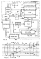
- Fig. 5 is a block diagram of a driving logic circuit of the printer of Fig. 1;
- Fig. 6 is a diagrammatic representation of the printing process obtained with the circuit of Fig. 5;
- Figure 7 is a partial section of a modified form of the head of Fig. 2.
- Referring to Fig. 1, the printer S comprises a
head 1 mounted on acarriage 10 moved alongguides 12 by anelectric motor 13 by means of acable 14. Thehead 1 is formed by a rigid structure 2 (Figs 2 and 3) consisting of afront plate 3 and arear plate 5 which are parallel to one another and kept spaced apart by twoside members 7, 9. - The
head 1 can print in both directions along a printing line L (Fig. 1) on acarrier 15 passed around aplaten 16. A synchronizingdevice 17 of known type, constituted, for example, by astrobe disc 18, keyed on the shaft of themotor 13, and aphotoelectric transducer 20, is used to generate strobe signals for synchronizing the printing with the movement of the head. - More particularly, as is known, the
timing device 17 generates the clock signals as a function of the position of the head along the printing line L and, therefore, the clock signals are independent of the speed of the head itself. By way of example, it is assumed that the synchronizingdevice 17 generates forty-two clock pulses while thehead 1 shifts by a distance equal to the pitch p (Fig. 4) between two adjacent nozzles. - In each of the
plates holes 22, for example twenty holes, which is inclined with respect to the direction of the movement of thecarriage 10, each hole in theplate 3 being aligned with the corresponding hole in theplate 5. Theholes 22 are equidistant by the pitch "p", measured in the direction of the movement of thecarriage 10. Into each pair ofcorresponding holes 22 there are now introducedcylindrical tubes 24 adapted to contain ink which is to be expelled in the form of drops by a known technique, as will be described hereinafter. All thetubes 24 lie in a plane having the course F'-F' indicated by a chain-dotted line in Fig. 4 and the inclination of which is such that the distance between the first and the last hole of the row, measured perpendicularly to the direction of the movement of thecarriage 10, is equal to the maximum height of the characters printed on thepaper 15. Thetubes 24 are firmly fixed in theholes 22 of theplates front end 26 thereof is positioned level with theouter surface 27 of theplate 3. - The
tubes 24 project from therear plate 5 by a certain length to permit their connection by means of thetubes 30 to anauxiliary ink reservoir 31 connected in turn by means of aflexible tube 32 to a main reservoir not illustrated in the drawings. Theauxiliary reservoir 31 is fixed at the rear of thecarriage 10 on awall 33 of a paral-lelepipedal container 34 for protecting thetubes 30. - Inside the
container 34, thetubes 30, which are of flexible material, are supported by acylindrical drum 130 fixed to theside walls 132 of thecontainer 34 by means of ashaft 133 coaxial with thedrum 130. Eachflexible tube 30 is wound around the outer surface of thedrum 130 for one and a half turns, inasmuch as it begins and ends, respectively, in two diametrically opposite positions with respect to thedrum 30. - Moreover, for the purpose of minimizing the space occupied by the
tubes 30 in the axial direction on thedrum 130, theflexible tubes 30 are wound around it alternately in opposite directions, whereby each half turn of the winding coil left free by one of thetubes 30 is occupied by the first half turn of the adjacent tube. - In this way, for each pair of
tubes 30 only three turns are used on thedrum 130, occupying, that is, a space in the axial direction equal to three diameters of thetubes 30, so that a total of thirty turns are necessary in all for the twentytubes 30. - In addition to optimizing the utilization of the space in the
container 34, this arrangement of thetubes 30 serves to prevent knocks between thetubes 30 caused by the forces of inertia generated by the movement of the carriage 10 (Fig. 1) at the stops and starts of the carriage. - The
tubes 24 may be of chemically inert material such as, for example, glass or ceramic, but they may also be of metal, for example stainless steel or nickel. On the tubes 24 (Fig. 3),piezoelectric transducers 36 in the form of sleeves are cemented approximately half way along the tubes, the transducers being adapted to contract radially under the effect of an electric voltage pulse applied to them. - To this end, the inner and outer surfaces of the
sleeves 36 are covered by twoelectrodes electrode 37 being brought over onto the outer surface of the sleeve to facilitate electrical connection. A printedcircuit board 40 is located between theplates sleeves 36. Theelectrodes corresponding tracks faces plate 40 projects at the bottom from the head (Figs. 3, 4) to permit electrical connection by means of a connector not shown in the drawings. - Inside the
structure 2 there is cast a resin polymerizable at room temperature and of low shrinkage, for example an epoxy resin, to form asingle block 48 enclosing all thetubes 24 and thecorresponding sleeves 36. - When hardening has taken place, the block of
resin 48 establishes a rigid and continuous connection between theplates resin 48 constitutes a reliable protection for the extremelyfragile tubes 24 against possible knocks or shocks. - Mounted removably against the
outer face 27 of thefront plate 3 by means ofscrews 50 is alamina 51 with a thickness less than that of theplate 3 and in which there are formed twenty nozzles Uo - ... Ui9, each of which is disposed in perfect alignment with respect to the
corresponding tube 24. The alignment of the nozzles U with therespective tubes 24 is ensured by locatingpins 52 fixed to theplate 3 and engaged in holes 53 in thelamina 51. In this way, thelamina 51 can be separated easily from theplate 3 to permit cleaning of the nozzles in the event of any of them becoming blocked because of drying of the printing ink. Each nozzle U is formed by anorifice 54 of cylindrical form of a diameter between 50 and 90 um, and a conically flaredportion 56 connecting theorifice 54 with the inner diameter of thetubes 24, which is of the order of 0.8 mm. - As already mentioned before, a drop of ink can be expelled from each nozzle U by the effect of the compression exerted by the
corresponding transducer 36 when energized by a voltage pulse. All thetransducers 36 are electrically connected through the medium of the printedcircuit board 40 and a 20-wire cable 45 indicated diagrammatically in Fig. 1 to anenergizing unit 58 of known type and not described in detail, which is able to energize selectively in parallel any or all of the twentytransducers 36. Theenergizing unit 58 receives in parallel on a bus 55 a string of twenty bits corresponding to the dots which are to be printed simultaneously by the twenty nozzles U. The printing bits are processed by adriving logic circuit 60 illustrated in Fig. 5, which comprises a read/writememory 62 with 1024 address locations. - The
memory 62 is connected through abus 64 to alatch 66 for temporary storage of the memory addresses which arrive on abus 68 from anaddress multiplexer 70 driven directly by amicroprocessor control unit 72 through abus 74. Anadder 76 executes at each cycle a shift by a predetermined number K of places to permit themultiplexer 70 to address correctly the information stored in thememory 62, in accordance with a procedure described later on. - The number K corresponds to the number of dots printable in the pitch "p" between two adjacent nozzles and can assume predetermined values. A manual entering
device 80, for example a switch with a plurality of sections, is connected to theadder 76 through the medium of abus 77 and enables the predetermined number K to be forced into theadder 76 in known manner. - Through a
bus 73, thecontroller 72 addresses acharacter generator 82 which contains the ciarac- ters to be printed in columns of dots in accordance with a predetermined matrix. The characters to be printed are extracted from a line memory known perse which is connected to thecontroller 72 and not shown in the drawings. Thegenerator 82 is connected via abus 83 to thememory 62 for storing in succession the information appertaining to the columns of dots of the characters to be printed. - The
memory 62 is constituted by 1024 address locations or positions Plo, ... P11, ... PI1024 with cyclic updating (Fig. 5). In each address position PI, there are stored the twenty bits relating to the dots of each column of the matrix of the character, which is formed in the present case by twenty rows Lo, L1, ... L,o (Fig. 6) (there being twenty nozzles) and a predetermined number of columns, for example forty-eight. Thememory 62 is connected through abus 85 to anoutput multiplexer 86 for reading the bits corresponding to the twenty nozzles of thehead 1. Themultiplexer 86 is driven by an up/downcounter 90, according to the direction of printing, which is adapted to count cyclically up to twenty, for successively transferring the bits of the dots to be printed, which are read out of thememory 62, by means of a wire 93 to a bidirectional/shift register 94 having twenty locations and of the serial input and parallel output type. The counting direction of thecounter 90 and theshift register 94 is supplied by thecontroller 72 on awire 91 on the basis of the desired direction of printing. Theregister 94 is connected through thebus 55 to the energizing unit 58 (Fig. 1) for transferring all the bits corresponding to the twenty nozzles U thereto in parallel on the basis of an enabling signal transmitted by thecontroller 72, in synchronism with the clock signal generated by the synchronizing device 17 (Fig. 1). Accordingly, as already mentioned, while thehead 1 shifts by one pitch "p", there will be forty-two printing energizations. - When the
head 1 is located in a generic position along the printing line L (Figs. 1 and 6), the first nozzle Uo will print the dot Po of a generic column of dots C, on a line Lo, the second nozzle will print the dot P1 corresponding to a column CI-42 shifted by forty-two printing positions with respect to the column C,, and so on, the nozzle U18 will print the dot P18 of the column Ci-756 and finally the nozzle U19 will print the dot P19 belonging to the column Cl-798, that is shifted back with respect to the direction of movement of thecarriage 10 by 798 printing positions with respect to the first column C,. - Taking it that, before beginning printing, the
memory 62 is completely erased, thecontroller 72, addressing the location Plo of thememory 62 through the medium of themultiplexer 70 and thelatch 66, writes in that location the information appertaining to the column C, prepared by thecharacter generator 82. In this state, thecounter 90 enables theoutput multiplexer 86 to extract the bit corresponding to the first nozzle Uo from the address position of the first column of dots C, and to load it into theregister 94. Then, assuming K=42, that is equal to the number of printing positions contained in a pitch "p", thecontroller 72 causes thelatch 66 to change over via theaddress multiplexer 70 to a memory location PI-42 set back by 42 positions with respect to the preceding one to address therein the information appertaining to the column Ci-42 corresponding to the second nozzle U1 and previously stored in thememory 62 in a stage similar to that hereinbefore described. The shifting by K-42 positions is executed by theadder 72, which adds the number K, entered on theswitch 80, to the serial number of the preceding address. - The
counter 90 is incrementd or decremented by one so that themultiplexer 86 extracts the bit corresponding to the second nozzle U1. This procedure will be repeated by degrees for all the twenty nozzles U. More particularly, the bit corresponding to the twentieth nozzle will be extracted from the last address location P1798, corresponding to the column Ci-798· - In the end, in the
register 94 there will be arranged serially in columns the twenty printing bits read in thememory 62, which represent the complete information which will be sent in parallel to the energizing unit 58 (Fig. 1) for printing. - After the
head 1 has shifted to the right by forty-two printing positions, for example, the second nozzle U1 has been brought onto the column C,, which belonged before to the first nozzle Uo, the third nozzle U2 has been brought onto the column C,-42, and so on, and the last nozzle U19 has been brought into vertical alignment on the penultimate column C1-756· - Finally, after the head has shifted by 798 printing positions, the nozzle U19 will be in vertical alignment on the column C,, which will be printed completely with the twenty dots belonging to it. Proceeding in a similar manner, all the columns of dots will be printed in this way and will form a complete row of vertically printed characters.
- The driving circuit of Fig. 5 enables the slope of the printed characters to be varied in one direction or the other with respect to the vertical by a simple operation. To vary the slope of the printed characters, it is sufficient to vary the number K forced into the
adder 76 by means of theswitch 80. - By entering a number K' less than K, a forward slope of the characters will be obtained, which will be all the more pronounced the more K' differs from K. On the other hand, in similar manner, a backward slope of the characters will be obtained by entering a number K" greater than K. In fact, let us supposed that we enter a number K'=41 by means of the
switch 80. In this situation, themultiplexer 86 will read the information of the column of dots corresponding to the second nozzle U1 in an address location in thememory 62 shifted by 41 locations, whereby the second nozzle U1 will print the dots in positions advanced by one step with respect to the preceding state. In a similar manner, all the other nozzles U2, U3, ... U19 will print their dot in a position advanced respectively by one, two, ... nineteen printing positions with respect to the normal state. In this way, an alignment of the dots of each printed column which is sloped forward will be obtained. In a completely similar manner, a backward slope of the columns of printed dots will be obtained if K is taken as greater than 42. - The printing speed can be considerably increased due to the cyclic updating of the
memory 62. In fact, as already described hereinbefore, the information relating to the columns of dots of the characters to be printed is stored in thememory 62 in cyclic succession; simultaneously, theoutput multiplexer 86 extracts successively from each column just stored a bit corresponding to the dot to be printed by means of each of the twenty nozzles of the head. In consequence, due to the simultaneousness of the writing and reading of the information in thememory 62, the speed of loading of theregister 94 by themultiplexer 86 is considerably increased. As a result, the printing speed of the nozzles can also be increased up to values such as to be able to turn to account the maximum frequency of repetition of the emission of drops of ink by each piezoelectric element. - Among many possible modifications, we mention that the number K selected to vary the slope of the characters may be entered directly from the
controller 72 instead of through the switch 80 (Fig. 5). In this case, the number K selected is forced directly by thecontroller 72 into theadder 76 on the basis of predetermined instructions processed by the controller in response to predetermined commands received in known manner. Consequently, the enteringdevice 80 in Fig. 5 is eliminated and thebus 77 is connected between thecontroller 72 and theadder 76. - Moreover, in order to facilitate the operations of mounting and removal of the head of Figs. 1 and 2, the
tubes 24 can be cut so as not to project from the rear plate 5 (Fig. 7). Small pieces of tubing 24' projecting inside thecontainer 34 are cemented through the front plate 33' of thecontainer 34. Thetubes 30 are fitted over these small pieces 24'. In this way, thecontainer 34 can be separated from theblock 48 without having to slip thetubes 30 off thetubes 24. The plate 33' of thecontainer 34 is fixed rigidly by means of screws and locating pins, not shown in the drawing, so as to ensure registration between thetubes 24 and 24'.
Claims (9)
Priority Applications (1)
| Application Number | Priority Date | Filing Date | Title |
|---|---|---|---|
| EP19860200146 EP0185652B1 (en) | 1981-08-04 | 1982-07-19 | Ink jet dot printing head |
Applications Claiming Priority (3)
| Application Number | Priority Date | Filing Date | Title |
|---|---|---|---|
| IT68093/81A IT1144625B (en) | 1981-08-04 | 1981-08-04 | INK JET POINTER PRINTER |
| IT6809381 | 1981-08-04 | ||
| EP19860200146 EP0185652B1 (en) | 1981-08-04 | 1982-07-19 | Ink jet dot printing head |
Related Parent Applications (2)
| Application Number | Title | Priority Date | Filing Date |
|---|---|---|---|
| EP82303776A Division-Into EP0072110B1 (en) | 1981-08-04 | 1982-07-19 | Ink jet dot printer |
| EP82303776A Division EP0072110B1 (en) | 1981-08-04 | 1982-07-19 | Ink jet dot printer |
Publications (3)
| Publication Number | Publication Date |
|---|---|
| EP0185652A2 EP0185652A2 (en) | 1986-06-25 |
| EP0185652A3 EP0185652A3 (en) | 1986-10-01 |
| EP0185652B1 true EP0185652B1 (en) | 1989-05-24 |
Family
ID=26102961
Family Applications (1)
| Application Number | Title | Priority Date | Filing Date |
|---|---|---|---|
| EP19860200146 Expired EP0185652B1 (en) | 1981-08-04 | 1982-07-19 | Ink jet dot printing head |
Country Status (1)
| Country | Link |
|---|---|
| EP (1) | EP0185652B1 (en) |
Family Cites Families (6)
| Publication number | Priority date | Publication date | Assignee | Title |
|---|---|---|---|---|
| US3832579A (en) * | 1973-02-07 | 1974-08-27 | Gould Inc | Pulsed droplet ejecting system |
| DE2543420C3 (en) * | 1975-09-29 | 1980-09-11 | Siemens Ag, 1000 Berlin Und 8000 Muenchen | Piezoelectric drive element for writing heads in ink mosaic writing devices |
| US4032929A (en) * | 1975-10-28 | 1977-06-28 | Xerox Corporation | High density linear array ink jet assembly |
| US4025928A (en) * | 1976-04-19 | 1977-05-24 | Gould Inc. | Unitary ink jet and reservoir |
| JPS55126461A (en) * | 1979-03-26 | 1980-09-30 | Canon Inc | Cartridge-type recording head |
| JPS5660259A (en) * | 1979-10-22 | 1981-05-25 | Ricoh Co Ltd | Ink-jet head |
-
1982
- 1982-07-19 EP EP19860200146 patent/EP0185652B1/en not_active Expired
Also Published As
| Publication number | Publication date |
|---|---|
| EP0185652A3 (en) | 1986-10-01 |
| EP0185652A2 (en) | 1986-06-25 |
Similar Documents
| Publication | Publication Date | Title |
|---|---|---|
| EP0072110B1 (en) | Ink jet dot printer | |
| US4415909A (en) | Multiple nozzle ink jet print head | |
| JP2974624B2 (en) | Ink jet print head identification circuit with sequential output dynamic shift register | |
| US6659581B2 (en) | Integrated programmable fire pulse generator for inkjet printhead assembly | |
| EP0445916B1 (en) | Recording head and recording apparatus using same | |
| US20060268056A1 (en) | Non-staggered inkjet printhead with true multiple resolution support | |
| CA1186365A (en) | Ink jet print head | |
| JPS62108061A (en) | Ink jet printing head | |
| US4158204A (en) | Time correction system for multi-nozzle ink jet printer | |
| KR100395838B1 (en) | Inkjet Printers and Their Driving Methods | |
| JP3131078B2 (en) | Image recording device | |
| JPS6016677B2 (en) | Printer control signal giving device | |
| EP0997281B1 (en) | Ink ejection element firing order to minimize horizontal banding and the jaggedness of vertical lines | |
| US4289411A (en) | Multilingual ink jet printer | |
| EP0214855B1 (en) | Drop-on-demand ink-jet printing apparatus | |
| GB2086628A (en) | Printing control device for thermal printer | |
| US4167342A (en) | Control system for matrix print head | |
| EP0185652B1 (en) | Ink jet dot printing head | |
| US3810195A (en) | Helical bar printer logic circuitry | |
| JPS5971869A (en) | Drive circuit for hot ink jet printer | |
| EP0303124B1 (en) | Control for enabling flight timing of hammers during printing | |
| JP2011073392A (en) | Method for manufacturing liquid jetting head | |
| US4485388A (en) | Compact print head | |
| JP2002160362A (en) | Driving device for ink jet head | |
| US4713623A (en) | Control system for matrix print head |
Legal Events
| Date | Code | Title | Description |
|---|---|---|---|
| PUAI | Public reference made under article 153(3) epc to a published international application that has entered the european phase |
Free format text: ORIGINAL CODE: 0009012 |
|
| AC | Divisional application: reference to earlier application |
Ref document number: 72110 Country of ref document: EP |
|
| AK | Designated contracting states |
Kind code of ref document: A2 Designated state(s): DE FR GB |
|
| PUAL | Search report despatched |
Free format text: ORIGINAL CODE: 0009013 |
|
| AK | Designated contracting states |
Kind code of ref document: A3 Designated state(s): DE FR GB |
|
| 17P | Request for examination filed |
Effective date: 19870317 |
|
| 17Q | First examination report despatched |
Effective date: 19880704 |
|
| GRAA | (expected) grant |
Free format text: ORIGINAL CODE: 0009210 |
|
| AC | Divisional application: reference to earlier application |
Ref document number: 72110 Country of ref document: EP |
|
| AK | Designated contracting states |
Kind code of ref document: B1 Designated state(s): DE FR GB |
|
| PG25 | Lapsed in a contracting state [announced via postgrant information from national office to epo] |
Ref country code: FR Free format text: THE PATENT HAS BEEN ANNULLED BY A DECISION OF A NATIONAL AUTHORITY Effective date: 19890524 |
|
| REF | Corresponds to: |
Ref document number: 3279708 Country of ref document: DE Date of ref document: 19890629 |
|
| EN | Fr: translation not filed | ||
| PLBE | No opposition filed within time limit |
Free format text: ORIGINAL CODE: 0009261 |
|
| STAA | Information on the status of an ep patent application or granted ep patent |
Free format text: STATUS: NO OPPOSITION FILED WITHIN TIME LIMIT |
|
| 26N | No opposition filed | ||
| PGFP | Annual fee paid to national office [announced via postgrant information from national office to epo] |
Ref country code: DE Payment date: 19900831 Year of fee payment: 9 |
|
| PGFP | Annual fee paid to national office [announced via postgrant information from national office to epo] |
Ref country code: GB Payment date: 19910705 Year of fee payment: 10 |
|
| PG25 | Lapsed in a contracting state [announced via postgrant information from national office to epo] |
Ref country code: DE Effective date: 19920401 |
|
| PG25 | Lapsed in a contracting state [announced via postgrant information from national office to epo] |
Ref country code: GB Effective date: 19920719 |
|
| GBPC | Gb: european patent ceased through non-payment of renewal fee |
Effective date: 19920719 |