EP0185629B1 - Resistance welding apparatus - Google Patents
Resistance welding apparatus Download PDFInfo
- Publication number
- EP0185629B1 EP0185629B1 EP85830312A EP85830312A EP0185629B1 EP 0185629 B1 EP0185629 B1 EP 0185629B1 EP 85830312 A EP85830312 A EP 85830312A EP 85830312 A EP85830312 A EP 85830312A EP 0185629 B1 EP0185629 B1 EP 0185629B1
- Authority
- EP
- European Patent Office
- Prior art keywords
- current
- electrical
- converter circuit
- supplied
- welding
- Prior art date
- Legal status (The legal status is an assumption and is not a legal conclusion. Google has not performed a legal analysis and makes no representation as to the accuracy of the status listed.)
- Expired
Links
- 238000003466 welding Methods 0.000 title claims description 51
- 238000004804 winding Methods 0.000 claims description 15
- 230000000737 periodic effect Effects 0.000 claims description 6
- 230000003019 stabilising effect Effects 0.000 claims description 2
- 230000004913 activation Effects 0.000 claims 2
- 238000010586 diagram Methods 0.000 description 5
- 230000008901 benefit Effects 0.000 description 4
- 230000000694 effects Effects 0.000 description 3
- 239000002184 metal Substances 0.000 description 3
- 230000009471 action Effects 0.000 description 2
- 239000003990 capacitor Substances 0.000 description 2
- 230000009849 deactivation Effects 0.000 description 2
- 238000000034 method Methods 0.000 description 2
- 230000008569 process Effects 0.000 description 2
- 230000033228 biological regulation Effects 0.000 description 1
- 230000015556 catabolic process Effects 0.000 description 1
- 230000001276 controlling effect Effects 0.000 description 1
- 125000004122 cyclic group Chemical group 0.000 description 1
- 230000008030 elimination Effects 0.000 description 1
- 238000003379 elimination reaction Methods 0.000 description 1
- 230000017525 heat dissipation Effects 0.000 description 1
- 230000006872 improvement Effects 0.000 description 1
- 230000001939 inductive effect Effects 0.000 description 1
- 238000012544 monitoring process Methods 0.000 description 1
- 239000000523 sample Substances 0.000 description 1
- 238000012163 sequencing technique Methods 0.000 description 1
- 230000003068 static effect Effects 0.000 description 1
- 238000011282 treatment Methods 0.000 description 1
- 238000005493 welding type Methods 0.000 description 1
Images

Classifications
-
- B—PERFORMING OPERATIONS; TRANSPORTING
- B23—MACHINE TOOLS; METAL-WORKING NOT OTHERWISE PROVIDED FOR
- B23K—SOLDERING OR UNSOLDERING; WELDING; CLADDING OR PLATING BY SOLDERING OR WELDING; CUTTING BY APPLYING HEAT LOCALLY, e.g. FLAME CUTTING; WORKING BY LASER BEAM
- B23K11/00—Resistance welding; Severing by resistance heating
- B23K11/24—Electric supply or control circuits therefor
- B23K11/25—Monitoring devices
- B23K11/252—Monitoring devices using digital means
Definitions
- the present invention relates to electrical spot welding apparatus and is particularly concerned with welding apparatus for mounting at the end of a robot arm comprising:
- Welding apparatus of the type specified above, but for stationary use, is known, for instance, from DE-A-3344631 is currently used in the motor vehicle industry for welding parts of motor vehicle bodies.
- Such apparatus is being integrated in automated (robotised) body assembly plants, in which the welding electrodes are mounted at the free end of a robot arm. The arm is oriented by a digital control system so as to make the electrodes clamp between them those zones of the parts to be welded where the spot welds are to be made in a cyclic sequence which is to be carried out automatically.
- the transformer has such a weight and size such as to make it practically impossible to mount it on the arm of the robot adjacent the welding electrodes.
- Electrical cables must be connected between the transformer and the electrodes and these have considerable cross-sections and consequently a rigidity such as to obstruct the orienting movement of the robot arm.
- Such supply cables are also very expensive, deteriorate gradually in use and must be replaced periodically.
- the object of the present invention is to provide electrical welding apparatus in which the disadvantages described are eliminated, and also to provide apparatus with an improved efficiency, this term meaning the ratio between the energy effectively applied to the welding electrodes and the energy absorbed by the apparatus.
- a converter circuit is connected between the electrical current source and the transformer and, from the electrical power supplied by the source, generates a periodic electrical current at intermediate frequency (as defined below) which is supplied to the primary winding of the transformer, and
- a rectifier element is associated with the secondary winding, whereby the electrodes are supplied with a rectified, substantially direct current.
- periodic electrical current at intermediate frequency is intended to mean a periodic current whose period corresponds to a frequency of the order of several hundred Hertz.
- this intermediate frequency current is constituted by a rectangular-wave (square-wave) electrical current having a frequency of the order of 400 Hertz.
- the term "at intermediate frequency” has been used to clearly distinguish the frequency of the current generated by the converter circuit of the apparatus according to the invention from electrical currents used in the known types of welding apparatus, that is, alternating or periodic currents whose periodicity corresponds to the frequencies (50-60 Hertz of currents supplied by the mains.
- a direct current for supplying the welding electrodes has the advantage of eliminating the effects which, with alternating welding currents, are induced during the welding process upon variations in the metallic mass "embraced" by the welding electrodes. This mass actually varies according to the relative position of the electrodes and the pieces which are welded and is, for example, different according to whether the electrodes act on the edges or on central parts of the pieces.
- the converter circuit is a transistorised converter circuit: the choice of this type of converter allows considerably practical advantages to be obtained, particularly with regard to the possibility of generating rectangular waves with steep leading and trailing edges and the possibility of connecting the welding transformer directly to the converter without the need to interpose passive separating networks between them.
- FIG. 1 is a block schematic diagram of the structure of welding apparatus according to the invention
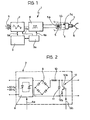
- Figure 2 is a circuit diagram illustrating the internal structure of one of the blocks of the diagram of Figure 1, and
- Figure 3 comprises several superposed time graphs in which typical waveforms of the current present at various points in the apparatus of Figure 1 and the circuit diagram of Figure 2 are shown qualitatively.
- electrical resistance welding apparatus for use, for example, in a plant for assembling motor vehicle bodies is generally indicated 1.
- the apparatus 1 comprises essentially:
- the electrodes 7 are arranged in a general gripper configuration which allows them to clamp metal parts to be welded in use. These parts are schematically illustrated in broken outline and indicated S in Figure 1.
- the control device 3 has associated probes and sensors (not explicitly illustrated in the drawings) which enable the progress of the welding operations to be checked (monitored) continuously or almost continuously.
- the device 3, which acts on the supply source 2, can thus regulate the progress of the welding process in a suitable manner according to a general feeback scheme.
- the detailed illustration of the manner in which this monitoring operation is carried out and the internal structure of the device 3 (which may be constituted, to advantage, by the CSA 80 control device produced by the Applicants) is not essential for an understanding of the present invention and will thus be omitted from the present description. It should be noted, however, that one of the considerable advantages of the present invention is actually due to the fact that it can be put into effect by modifying welding operation of known type currently in use, without the need for radical changes in the structure and the criteria of use of the apparatus itself.
- a shutter circuit comprises, for example, two SCRs or two ignitrons connected in an anti-parallel arrangement.
- the operation of the circuit 8, which allows the gradual shutting-off of the sinusoidal waveform of the current taken from the mains by the variation of the so-called angle of welding, is controlled (in known manner) by triggering pulses generated by the control device 3 on a line 8a.
- a rectifier bridge 9 Downstream of the shutter circuit 8 is a rectifier bridge 9 to which is also connected an inductive-capacitive buffer network (illustrated here simply in the form of an inductor 10 and a capacitor 11) whose object is essentially that of carrying out an integrating action on the rectified current leaving the rectifying bridge circuit 9 so as to ensure constant and stable operation of the converter 4 (inverter) supplied by the source 2.
- an inductive-capacitive buffer network illustrated here simply in the form of an inductor 10 and a capacitor 11
- the converter 4 is preferably an inverter constituted by four transistors driven alternatively in diagonal pairs by control pulses generated by the auxiliary module 3a on a group of lines, generally indicated 4a.
- This module is thus essentially a sequencer or timer which can generate control pulses in predetermined time sequences which are selectively regulable from the outside, for example through the circuit 3.
- the criteria for making sequencing or shutter modules, such as the module 3a, are fully known to experts in the art and will therefore not be described in detail.
- transistorised inverter for the converter 4 is a preferred solution over other possible choices (for example an SCR).
- SCR for example an SCR.
- transistors in fact allows very rapid switching to be achieved, rectangular waves with steep leading and trailing edges being generated.
- a discharge circuit of the inductive-capacitive network is indicated 12 and is represented schematically in the form of a transistor 12a and a resistor 12b connected together in series so as to form a branch circuit in parallel with the capacitor 11. It is possible, however, to use electronic switches of different types (for example an SCR) instead of the transistor 12a.
- the function of the circuit 12, which receives control pulses from the auxiliary module 3a through a line 12c connected to the base of the transistor 12a, is to allow the discharge to the resistor 12b of the residual energy in the resistive- capacitive network 10, 11 at the end of each elementary welding operation (the application of a spot).
- the apparatus is supplied with the current IN from the mains: this current therefore has a sinusoidal waveform with a frequency of 50 or 60 Hertz according to the distribution frequency adopted on a national or regional scale.
- the current IN is supplied to the shutter circuit 8.
- the electronic control switches SCRs or ignitrons which are in this circuit "cut", so to speak, the sinusoidal waveform of the current IN to give rise to the current I P the time behaviour of which is shown qualitatively in the second graph of Figure 3.
- the current I P thus has a waveform in which there can be distinguished sinusoidal portions separated by time intervals, indicated to, in which the current I P is zero.
- the duration of the intervals to relative to the period of the current I P is controlled selectively (in known manner) by the control device 3 which thus sets the so-called welding angle. More particularly, the device 3, by means of the partial shutting action effected by the circuit 8, regulates the effective (rms) value of the current which is sent (after further treatments) to the welding electrodes 7.
- the regulation of this rms value in dependence on the thickness and nature of the metal parts S to be welded, the wear of the electrodes, etc., is essential to ensure a good result from the welding operation.
- a welding operation the application of a spot
- Both the current IN taken from the mains and the partially shut-off current I P have a periodicity with a period corresponding to a low frequency, that is, a frequency of the order of several tens of Hertz (typically 50-60 Hertz).
- the current I P is rectified and subsequently supplied to the inductive-capacitive (reactive) network 10, 11 which effects an integrating (stabilising) operation on the current.
- the output from the source 2 is thus the current Is which may be defined essentially as a direct current.
- the current Is is also zero.
- the device 3 activates the source 2 and the current Is increases approximately exponentially (with a time constant determined by the values of the inductive and capacitive components 10, 11) until it reaches a constant or continuous value (the behaviour of the current Is is illustrated to the right of the interval tp in the third graph of Figure 3).
- This constant or continuous value is maintained until the device 3 deactivates the source 2 upon completion of the elementary welding operation (the application of a spot).
- the auxiliary module 3a activates (makes conductive) the transistor 12a so that the residual charge present in the inductive-capacitive network 10, 11 is discharged rapidly to the resistance 12b, giving rise to a very steep trailing edge in the current Is, indicated F d in the third graph of Figure 3.
- the device and the auxiliary module 3a associated therewith also have a controlling action on the other operating characteristics of the apparatus 1, in particular, limiting the voltage present in the rectifying bridge circuit 9 to a maximum admissible value, stopping the apparatus when breakdown or overloading of the apparatus occurs, etc.
- the transistorised converter 4 From the continuous current Is supplied to its input, the transistorised converter 4 generates an alternating current I c which is applied to the primary winding of the transformer 5.
- the current l c typically has a rectangular waveform whose period, indicated t s in the fourth graph of Figure 3, is of the order of 2.5 ms, corresponding to a frequency of 400 Hertz.
- the transformer 5 which is connected directly to the converter 4, that is without the interposition of separating networks, transforms the magnitude of the current which is supplied thereto and brings it to the values of 5-20 kA required by the electrodes 7 for carrying out the welding operations.
Description
- The present invention relates to electrical spot welding apparatus and is particularly concerned with welding apparatus for mounting at the end of a robot arm comprising:
- - a pair of welding electrodes which, in use, cooperate with each other with the interposition of the parts to be welded,
- - an electrical current source for connection to the mains and operating at a frequency subtan- tially corresponding to the frequency of the mains current, and
- - an electrical transformer mounted immediately adjacent the welding electrodes having a primary winding supplied by the electrical current source and a secondary winding which supplies the welding electrodes.
- Welding apparatus of the type specified above, but for stationary use, is known, for instance, from DE-A-3344631 is currently used in the motor vehicle industry for welding parts of motor vehicle bodies. To an ever-increasing extent, such apparatus is being integrated in automated (robotised) body assembly plants, in which the welding electrodes are mounted at the free end of a robot arm. The arm is oriented by a digital control system so as to make the electrodes clamp between them those zones of the parts to be welded where the spot welds are to be made in a cyclic sequence which is to be carried out automatically.
- It has been noted that the use of electrical welding apparatus of the type specified above in automated plants is hindered by several factors which may be considered as arising essentially from the dimensions of the transformer interposed between the source supplying the electrical current and the welding electrodes.
- Indeed, due to the high electrical power used, the transformer has such a weight and size such as to make it practically impossible to mount it on the arm of the robot adjacent the welding electrodes. Electrical cables must be connected between the transformer and the electrodes and these have considerable cross-sections and consequently a rigidity such as to obstruct the orienting movement of the robot arm. Such supply cables are also very expensive, deteriorate gradually in use and must be replaced periodically.
- The object of the present invention is to provide electrical welding apparatus in which the disadvantages described are eliminated, and also to provide apparatus with an improved efficiency, this term meaning the ratio between the energy effectively applied to the welding electrodes and the energy absorbed by the apparatus.
- According to the present invention, this object is achieved by welding apparatus of the type specified above, characterised in that:
- - a converter circuit is connected between the electrical current source and the transformer and, from the electrical power supplied by the source, generates a periodic electrical current at intermediate frequency (as defined below) which is supplied to the primary winding of the transformer, and
- - a rectifier element is associated with the secondary winding, whereby the electrodes are supplied with a rectified, substantially direct current.
- The term "periodic electrical current at intermediate frequency" is intended to mean a periodic current whose period corresponds to a frequency of the order of several hundred Hertz. For example-according to a preferred embodiment of the invention-this intermediate frequency current is constituted by a rectangular-wave (square-wave) electrical current having a frequency of the order of 400 Hertz.
- The term "at intermediate frequency" has been used to clearly distinguish the frequency of the current generated by the converter circuit of the apparatus according to the invention from electrical currents used in the known types of welding apparatus, that is, alternating or periodic currents whose periodicity corresponds to the frequencies (50-60 Hertz of currents supplied by the mains.
- The presence of a rectifier element on the secondary winding of the welding transformer, together with the use of a rectangular-wave (square-wave) current for the supply of the transformer itself, means that, during each welding operation, the electrodes are supplied with a current which is essentially a direct current with the exception of possible "spikes" resulting from the fact that the leading and trailing edges of the rectified rectangular wave are not perfectly vertical. Consequently, the apparatus according to the invention is considerably more efficient than known apparatus.
- Furthermore, the use of a direct current (as defined) for supplying the welding electrodes has the advantage of eliminating the effects which, with alternating welding currents, are induced during the welding process upon variations in the metallic mass "embraced" by the welding electrodes. This mass actually varies according to the relative position of the electrodes and the pieces which are welded and is, for example, different according to whether the electrodes act on the edges or on central parts of the pieces.
- Preferably, the converter circuit is a transistorised converter circuit: the choice of this type of converter allows considerably practical advantages to be obtained, particularly with regard to the possibility of generating rectangular waves with steep leading and trailing edges and the possibility of connecting the welding transformer directly to the converter without the need to interpose passive separating networks between them.
- The invention will now be described, purely by way of non-limiting example, with reference to the appended drawings, in which:
- Figure 1 is a block schematic diagram of the structure of welding apparatus according to the invention,
- Figure 2 is a circuit diagram illustrating the internal structure of one of the blocks of the diagram of Figure 1, and
- Figure 3 comprises several superposed time graphs in which typical waveforms of the current present at various points in the apparatus of Figure 1 and the circuit diagram of Figure 2 are shown qualitatively.
- In Figure 1, electrical resistance welding apparatus for use, for example, in a plant for assembling motor vehicle bodies is generally indicated 1.
- The apparatus 1 comprises essentially:
- - an electrical
current source 2 for connection to the mains N, - - a
control circuit 3 of known type which regulates the operation of thesource 2 and with which an auxiliary module, indicated 3a, is associated, - - converter circuit constituted, for example, by a transistorised static converter (inverter) supplied by the
source 2 and controlled by theauxiliary module 3a, - - a transformer 5 the primary winding of which indicated 5a, is connected to the output of the converter circuit 4, and
- - a pair of welding electrodes, generally indicated 7, connected to the
secondary winding 5b of the transformer 5 with the interposition of a rectifier element (a diode or group ofdiodes 5c). - In the preferred application to an automated (robotised) welding plant, the transformer 5 is mounted adjacent the end of the robot arm which carries the welding electrodes 7.
- In Figure 1, the end of this arm is schematically illustrated in broken outline and indicated R.
- The electrodes 7 are arranged in a general gripper configuration which allows them to clamp metal parts to be welded in use. These parts are schematically illustrated in broken outline and indicated S in Figure 1.
- In accordance with well-known criteria, the
control device 3 has associated probes and sensors (not explicitly illustrated in the drawings) which enable the progress of the welding operations to be checked (monitored) continuously or almost continuously. Thedevice 3, which acts on thesupply source 2, can thus regulate the progress of the welding process in a suitable manner according to a general feeback scheme. The detailed illustration of the manner in which this monitoring operation is carried out and the internal structure of the device 3 (which may be constituted, to advantage, by the CSA 80 control device produced by the Applicants) is not essential for an understanding of the present invention and will thus be omitted from the present description. It should be noted, however, that one of the considerable advantages of the present invention is actually due to the fact that it can be put into effect by modifying welding operation of known type currently in use, without the need for radical changes in the structure and the criteria of use of the apparatus itself. - In the block schematic diagram of Figure 2, a shutter circuit, generally indicated 8, comprises, for example, two SCRs or two ignitrons connected in an anti-parallel arrangement. The operation of the
circuit 8, which allows the gradual shutting-off of the sinusoidal waveform of the current taken from the mains by the variation of the so-called angle of welding, is controlled (in known manner) by triggering pulses generated by thecontrol device 3 on aline 8a. - Downstream of the
shutter circuit 8 is arectifier bridge 9 to which is also connected an inductive-capacitive buffer network (illustrated here simply in the form of aninductor 10 and a capacitor 11) whose object is essentially that of carrying out an integrating action on the rectified current leaving the rectifyingbridge circuit 9 so as to ensure constant and stable operation of the converter 4 (inverter) supplied by thesource 2. - As indicated above, the converter 4 is preferably an inverter constituted by four transistors driven alternatively in diagonal pairs by control pulses generated by the
auxiliary module 3a on a group of lines, generally indicated 4a. This module is thus essentially a sequencer or timer which can generate control pulses in predetermined time sequences which are selectively regulable from the outside, for example through thecircuit 3. The criteria for making sequencing or shutter modules, such as themodule 3a, are fully known to experts in the art and will therefore not be described in detail. - The choice of a transistorised inverter for the converter 4 is a preferred solution over other possible choices (for example an SCR). The use of transistors in fact allows very rapid switching to be achieved, rectangular waves with steep leading and trailing edges being generated.
- Furthermore, with the use of transistors, it is possible to connect the transformer 5 directly to the converter 4 without having to connect separating and protecting networks between them to avoid overloading of the converter due to any anomalies in the operation of the electrodes 7 (variations in the dimensions of the pieces S, imperfect closure of the electrodes 7 on the pieces S themselves, etc.).
- Finally, a discharge circuit of the inductive-capacitive network is indicated 12 and is represented schematically in the form of a
transistor 12a and aresistor 12b connected together in series so as to form a branch circuit in parallel with thecapacitor 11. It is possible, however, to use electronic switches of different types (for example an SCR) instead of thetransistor 12a. - The function of the
circuit 12, which receives control pulses from theauxiliary module 3a through aline 12c connected to the base of thetransistor 12a, is to allow the discharge to theresistor 12b of the residual energy in the resistive-capacitive network - The operation of the apparatus 1 will now be described in detail with reference to Figure 3.
- This Figure illustrates, in the form of superposed graphs referring to a single time scale on the abscissa, the typical time behaviour of the following currents:
- -the sinusoidal current IN taken from the mains and supplied to the input of the
source 2, - - the partially shut-off current lp present at the output of the
shutter circuit 8 of thesource 2, - - the current Is generated at the output of the
source 2 and supplied to the converter 4, - - the current Ic generated by the converter 4 and used to supply the primary winding of the transformer 5, and
- - the welding current IT applied to the electrodes 7 clamped on the metal parts S to be welded by the circuit of the
secondary winding 5b of the transformer 5. - In use, the apparatus is supplied with the current IN from the mains: this current therefore has a sinusoidal waveform with a frequency of 50 or 60 Hertz according to the distribution frequency adopted on a national or regional scale. The current IN is supplied to the
shutter circuit 8. The electronic control switches (SCRs or ignitrons) which are in this circuit "cut", so to speak, the sinusoidal waveform of the current IN to give rise to the current IP the time behaviour of which is shown qualitatively in the second graph of Figure 3. The current IP thus has a waveform in which there can be distinguished sinusoidal portions separated by time intervals, indicated to, in which the current IP is zero. - The duration of the intervals to relative to the period of the current IP is controlled selectively (in known manner) by the
control device 3 which thus sets the so-called welding angle. More particularly, thedevice 3, by means of the partial shutting action effected by thecircuit 8, regulates the effective (rms) value of the current which is sent (after further treatments) to the welding electrodes 7. The regulation of this rms value in dependence on the thickness and nature of the metal parts S to be welded, the wear of the electrodes, etc., is essential to ensure a good result from the welding operation. - The
control device 3 itself then controls periodically the interruption of the supply of the current IP (IP=0) for time intervals indicated tp. Typically, one is dealing with the time intervals needed to move the welding electrodes 7 from one region of the parts or pieces S where a welding operation (the application of a spot) has been carried out to another region of the same pieces, or to other pieces to be welded. - Both the current IN taken from the mains and the partially shut-off current IP have a periodicity with a period corresponding to a low frequency, that is, a frequency of the order of several tens of Hertz (typically 50-60 Hertz).
- In the
bridge circuit 9, the current IP is rectified and subsequently supplied to the inductive-capacitive (reactive)network - The output from the
source 2 is thus the current Is which may be defined essentially as a direct current. - More precisely, as illustrated qualitatively in the third graph of Figure 3, during the time intervals tp in which the
source 2 is deactivated, the current Is is also zero. As soon as an exemplary welding operation (the application of a spot) is started thedevice 3 activates thesource 2 and the current Is increases approximately exponentially (with a time constant determined by the values of the inductive andcapacitive components 10, 11) until it reaches a constant or continuous value (the behaviour of the current Is is illustrated to the right of the interval tp in the third graph of Figure 3). - This constant or continuous value is maintained until the
device 3 deactivates thesource 2 upon completion of the elementary welding operation (the application of a spot). - Upon deactivation of the
source 2, theauxiliary module 3a activates (makes conductive) thetransistor 12a so that the residual charge present in the inductive-capacitive network resistance 12b, giving rise to a very steep trailing edge in the current Is, indicated Fd in the third graph of Figure 3. - In addition to the functions described previously, the device and the
auxiliary module 3a associated therewith also have a controlling action on the other operating characteristics of the apparatus 1, in particular, limiting the voltage present in the rectifyingbridge circuit 9 to a maximum admissible value, stopping the apparatus when breakdown or overloading of the apparatus occurs, etc. - From the continuous current Is supplied to its input, the transistorised converter 4 generates an alternating current Ic which is applied to the primary winding of the transformer 5. The current lc typically has a rectangular waveform whose period, indicated ts in the fourth graph of Figure 3, is of the order of 2.5 ms, corresponding to a frequency of 400 Hertz.
- One is thus considering, according to the terminology adopted in the following claims, a current "at intermediate frequency", so called to distinguish it from the "low frequency" currents IN, IP present in the
supply source 2. - The supply with an intermediate frequency current-other things being equal-allows the dimensions and weight of the transformer 5 to be reduced relative to the dimensions and weight of welding transformers of known type which operate with low-frequency currents.
- In addition to this, the use of a rectangular waveform (square-wave) further improves the performance of the transformer 5, increasing its efficiency and reducing its heat dissipation.
- The transformer 5, which is connected directly to the converter 4, that is without the interposition of separating networks, transforms the magnitude of the current which is supplied thereto and brings it to the values of 5-20 kA required by the electrodes 7 for carrying out the welding operations.
- Due to the presence of the
rectifier element 5c, the current in the circuit of the secondary winding of the transformer 5 is a rectified current IT with a behaviour of the type shown schematically in the last graph of Figure 3. - One is dealing with a current which is more or less constant during each of the elementary welding cycles separated by the periods of deactivation tp. More precisely, as is normally the case for currents obtained by rectifying rectangular waveforms, the behaviour of the current IT is defined by a continuous line of constant level (with the exception, of course, of the leading edge which is shown at the beginning of each elementary welding operation) with "spikes"-one of which is indicated schematically by isp-whose presence is due to the fact that the leading and trailing edges in the rectangular waveform of the current Ic are not perfectly vertical.
- The influence of these spikes on the operation of the electrodes 7, however, is negligible; during each elementary welding operation (the application of a spot), the electrodes 7 are thus supplied with a substantially direct current which allows the achievement of considerable overall efficiency in the welding operation, with a considerable improvement in the energy efficiency of the apparatus, and the elimination of perturbations which may be induced by variations in the metallic mass of the parts gripped between the electrodes 7.
- As a basic consideration, it should be noted that the scales of the ordinates in the various graphs of Figure 3 are not proportionate to each other. Each graph is in fact represented in a scale such as to allow a sufficiently clear representation of its more significant parameters.
- Naturally, the principle of the invention remaining the same, the constructional details and forms of embodiment may be varied widely with respect to that described and illustrated, without thereby departing from the scope of the present invention as defined by the claims.
Claims (8)
Applications Claiming Priority (2)
| Application Number | Priority Date | Filing Date | Title |
|---|---|---|---|
| IT68276/84A IT1179889B (en) | 1984-12-21 | 1984-12-21 | RESISTANCE ELECTRIC WELDING EQUIPMENT |
| IT6827684 | 1984-12-21 |
Publications (4)
| Publication Number | Publication Date |
|---|---|
| EP0185629A2 EP0185629A2 (en) | 1986-06-25 |
| EP0185629A3 EP0185629A3 (en) | 1988-01-13 |
| EP0185629B1 true EP0185629B1 (en) | 1989-08-16 |
| EP0185629B2 EP0185629B2 (en) | 1993-09-29 |
Family
ID=11308801
Family Applications (1)
| Application Number | Title | Priority Date | Filing Date |
|---|---|---|---|
| EP85830312A Expired - Lifetime EP0185629B2 (en) | 1984-12-21 | 1985-12-18 | Resistance welding apparatus |
Country Status (3)
| Country | Link |
|---|---|
| EP (1) | EP0185629B2 (en) |
| DE (1) | DE3572317D1 (en) |
| IT (1) | IT1179889B (en) |
Cited By (1)
| Publication number | Priority date | Publication date | Assignee | Title |
|---|---|---|---|---|
| DE4308769A1 (en) * | 1993-03-19 | 1994-09-22 | Bosch Gmbh Robert | Diode monitoring |
Families Citing this family (1)
| Publication number | Priority date | Publication date | Assignee | Title |
|---|---|---|---|---|
| US5300753A (en) * | 1992-06-25 | 1994-04-05 | Axis Usa, Incorporated | Methods and apparatus for fusing electrical conductors |
Family Cites Families (3)
| Publication number | Priority date | Publication date | Assignee | Title |
|---|---|---|---|---|
| US3636298A (en) * | 1969-10-20 | 1972-01-18 | Cutler Hammer Inc | Static square-wave resistance tube welding system |
| EP0064570B2 (en) * | 1981-05-13 | 1990-07-11 | L. SCHULER GmbH | Electric energy source for a resistance welding machine |
| DE3344631A1 (en) * | 1982-12-24 | 1984-07-05 | Honda Giken Kogyo K.K., Tokio/Tokyo | WELDING GUN DEVICE |
-
1984
- 1984-12-21 IT IT68276/84A patent/IT1179889B/en active
-
1985
- 1985-12-18 DE DE8585830312T patent/DE3572317D1/en not_active Expired
- 1985-12-18 EP EP85830312A patent/EP0185629B2/en not_active Expired - Lifetime
Cited By (1)
| Publication number | Priority date | Publication date | Assignee | Title |
|---|---|---|---|---|
| DE4308769A1 (en) * | 1993-03-19 | 1994-09-22 | Bosch Gmbh Robert | Diode monitoring |
Also Published As
| Publication number | Publication date |
|---|---|
| EP0185629A3 (en) | 1988-01-13 |
| EP0185629B2 (en) | 1993-09-29 |
| IT8468276A0 (en) | 1984-12-21 |
| IT1179889B (en) | 1987-09-16 |
| EP0185629A2 (en) | 1986-06-25 |
| DE3572317D1 (en) | 1989-09-21 |
Similar Documents
| Publication | Publication Date | Title |
|---|---|---|
| US4201906A (en) | Method and apparatus for arc welding | |
| EP0508961B1 (en) | High-frequency switching-type protected power supply, in particular for electrostatic precipitators | |
| US5120929A (en) | Dc resistance welding apparatus | |
| US4973815A (en) | Resistance welder using an inverter | |
| US6046424A (en) | Resistance welding control apparatus | |
| US4246465A (en) | Pulsed-arc D.C. TIG welding apparatus | |
| EP0756914A2 (en) | Method and apparatus for controlling inverter resistance welding | |
| US5196668A (en) | DC resistance welding apparatus | |
| EP0185629B1 (en) | Resistance welding apparatus | |
| US5229567A (en) | Switching control system for controlling an inverter of a spot resistance welding apparatus | |
| CA1271516A (en) | Method of automatically controlling an electrostatic precipitator | |
| SU1530086A3 (en) | Method of controlling welding set with frequency converter | |
| JPH01292790A (en) | Inverter power supply for magnetron | |
| Hamasaki et al. | Harmonics compensation in high frequency range of active power filter with SiC-MOSFET inverter in digital control system | |
| CA1255761A (en) | Electronic device for controlling the supply of electrical power to resistance welding equipment, in particular as used in metal box construction | |
| CN111630764A (en) | Power supply device and welding power supply device | |
| EP0185014B1 (en) | Resistance welder | |
| WO1986000035A1 (en) | Resistance welder | |
| Golob | Modelling and Simulation of GMA Welding Process and Welding Power Sources. | |
| KR950001779B1 (en) | Source of electric power of plasma welding torch | |
| JP2507295B2 (en) | Resistance welding machine | |
| CA2145780C (en) | Dc resistance welding apparatus | |
| SU1547988A1 (en) | Power supply source for a.c. welding arc | |
| SU1563911A1 (en) | Apparatus for d.c. arc welding | |
| SU1131046A1 (en) | Induction installation for heating ferromagnetic articles |
Legal Events
| Date | Code | Title | Description |
|---|---|---|---|
| PUAI | Public reference made under article 153(3) epc to a published international application that has entered the european phase |
Free format text: ORIGINAL CODE: 0009012 |
|
| AK | Designated contracting states |
Kind code of ref document: A2 Designated state(s): BE DE FR GB NL SE |
|
| PUAL | Search report despatched |
Free format text: ORIGINAL CODE: 0009013 |
|
| AK | Designated contracting states |
Kind code of ref document: A3 Designated state(s): BE DE FR GB NL SE |
|
| 17P | Request for examination filed |
Effective date: 19880312 |
|
| 17Q | First examination report despatched |
Effective date: 19880624 |
|
| GRAA | (expected) grant |
Free format text: ORIGINAL CODE: 0009210 |
|
| AK | Designated contracting states |
Kind code of ref document: B1 Designated state(s): BE DE FR GB NL SE |
|
| REF | Corresponds to: |
Ref document number: 3572317 Country of ref document: DE Date of ref document: 19890921 |
|
| ET | Fr: translation filed | ||
| PLBI | Opposition filed |
Free format text: ORIGINAL CODE: 0009260 |
|
| 26 | Opposition filed |
Opponent name: ROBERT BOSCH GMBH Effective date: 19900516 |
|
| NLR1 | Nl: opposition has been filed with the epo |
Opponent name: ROBERT BOSCH GMBH |
|
| PUAH | Patent maintained in amended form |
Free format text: ORIGINAL CODE: 0009272 |
|
| STAA | Information on the status of an ep patent application or granted ep patent |
Free format text: STATUS: PATENT MAINTAINED AS AMENDED |
|
| 27A | Patent maintained in amended form |
Effective date: 19930929 |
|
| AK | Designated contracting states |
Kind code of ref document: B2 Designated state(s): BE DE FR GB NL SE |
|
| NLR2 | Nl: decision of opposition | ||
| ET3 | Fr: translation filed ** decision concerning opposition | ||
| NLR3 | Nl: receipt of modified translations in the netherlands language after an opposition procedure | ||
| EAL | Se: european patent in force in sweden |
Ref document number: 85830312.6 |
|
| APAC | Appeal dossier modified |
Free format text: ORIGINAL CODE: EPIDOS NOAPO |
|
| APAC | Appeal dossier modified |
Free format text: ORIGINAL CODE: EPIDOS NOAPO |
|
| PGFP | Annual fee paid to national office [announced via postgrant information from national office to epo] |
Ref country code: SE Payment date: 19971211 Year of fee payment: 13 |
|
| PGFP | Annual fee paid to national office [announced via postgrant information from national office to epo] |
Ref country code: FR Payment date: 19971230 Year of fee payment: 13 |
|
| PGFP | Annual fee paid to national office [announced via postgrant information from national office to epo] |
Ref country code: GB Payment date: 19980121 Year of fee payment: 13 |
|
| PGFP | Annual fee paid to national office [announced via postgrant information from national office to epo] |
Ref country code: DE Payment date: 19980126 Year of fee payment: 13 |
|
| PGFP | Annual fee paid to national office [announced via postgrant information from national office to epo] |
Ref country code: NL Payment date: 19980127 Year of fee payment: 13 |
|
| PGFP | Annual fee paid to national office [announced via postgrant information from national office to epo] |
Ref country code: BE Payment date: 19980205 Year of fee payment: 13 |
|
| PG25 | Lapsed in a contracting state [announced via postgrant information from national office to epo] |
Ref country code: GB Free format text: LAPSE BECAUSE OF NON-PAYMENT OF DUE FEES Effective date: 19981218 |
|
| PG25 | Lapsed in a contracting state [announced via postgrant information from national office to epo] |
Ref country code: SE Free format text: LAPSE BECAUSE OF NON-PAYMENT OF DUE FEES Effective date: 19981219 |
|
| PG25 | Lapsed in a contracting state [announced via postgrant information from national office to epo] |
Ref country code: BE Free format text: LAPSE BECAUSE OF NON-PAYMENT OF DUE FEES Effective date: 19981231 |
|
| BERE | Be: lapsed |
Owner name: COMAU S.P.A. Effective date: 19981231 |
|
| PG25 | Lapsed in a contracting state [announced via postgrant information from national office to epo] |
Ref country code: NL Free format text: LAPSE BECAUSE OF NON-PAYMENT OF DUE FEES Effective date: 19990701 |
|
| GBPC | Gb: european patent ceased through non-payment of renewal fee |
Effective date: 19981218 |
|
| PG25 | Lapsed in a contracting state [announced via postgrant information from national office to epo] |
Ref country code: FR Free format text: LAPSE BECAUSE OF NON-PAYMENT OF DUE FEES Effective date: 19990831 |
|
| NLV4 | Nl: lapsed or anulled due to non-payment of the annual fee |
Effective date: 19990701 |
|
| REG | Reference to a national code |
Ref country code: FR Ref legal event code: ST |
|
| PG25 | Lapsed in a contracting state [announced via postgrant information from national office to epo] |
Ref country code: DE Free format text: LAPSE BECAUSE OF NON-PAYMENT OF DUE FEES Effective date: 19991001 |
|
| APAH | Appeal reference modified |
Free format text: ORIGINAL CODE: EPIDOSCREFNO |