EP0185402A1 - Method for constructing a concrete pile and device for the application of the method - Google Patents
Method for constructing a concrete pile and device for the application of the method Download PDFInfo
- Publication number
- EP0185402A1 EP0185402A1 EP19850201767 EP85201767A EP0185402A1 EP 0185402 A1 EP0185402 A1 EP 0185402A1 EP 19850201767 EP19850201767 EP 19850201767 EP 85201767 A EP85201767 A EP 85201767A EP 0185402 A1 EP0185402 A1 EP 0185402A1
- Authority
- EP
- European Patent Office
- Prior art keywords
- tube
- hammer
- driving
- concrete
- cone
- Prior art date
- Legal status (The legal status is an assumption and is not a legal conclusion. Google has not performed a legal analysis and makes no representation as to the accuracy of the status listed.)
- Withdrawn
Links
Images


Classifications
-
- E—FIXED CONSTRUCTIONS
- E02—HYDRAULIC ENGINEERING; FOUNDATIONS; SOIL SHIFTING
- E02D—FOUNDATIONS; EXCAVATIONS; EMBANKMENTS; UNDERGROUND OR UNDERWATER STRUCTURES
- E02D5/00—Bulkheads, piles, or other structural elements specially adapted to foundation engineering
- E02D5/22—Piles
- E02D5/34—Concrete or concrete-like piles cast in position ; Apparatus for making same
- E02D5/38—Concrete or concrete-like piles cast in position ; Apparatus for making same making by use of mould-pipes or other moulds
- E02D5/385—Concrete or concrete-like piles cast in position ; Apparatus for making same making by use of mould-pipes or other moulds with removal of the outer mould-pipes
-
- E—FIXED CONSTRUCTIONS
- E02—HYDRAULIC ENGINEERING; FOUNDATIONS; SOIL SHIFTING
- E02D—FOUNDATIONS; EXCAVATIONS; EMBANKMENTS; UNDERGROUND OR UNDERWATER STRUCTURES
- E02D11/00—Methods or apparatus specially adapted for both placing and removing sheet pile bulkheads, piles, or mould-pipes
-
- E—FIXED CONSTRUCTIONS
- E02—HYDRAULIC ENGINEERING; FOUNDATIONS; SOIL SHIFTING
- E02D—FOUNDATIONS; EXCAVATIONS; EMBANKMENTS; UNDERGROUND OR UNDERWATER STRUCTURES
- E02D7/00—Methods or apparatus for placing sheet pile bulkheads, piles, mouldpipes, or other moulds
- E02D7/02—Placing by driving
- E02D7/06—Power-driven drivers
- E02D7/14—Components for drivers inasmuch as not specially for a specific driver construction
- E02D7/16—Scaffolds or supports for drivers
-
- E—FIXED CONSTRUCTIONS
- E02—HYDRAULIC ENGINEERING; FOUNDATIONS; SOIL SHIFTING
- E02D—FOUNDATIONS; EXCAVATIONS; EMBANKMENTS; UNDERGROUND OR UNDERWATER STRUCTURES
- E02D7/00—Methods or apparatus for placing sheet pile bulkheads, piles, mouldpipes, or other moulds
- E02D7/22—Placing by screwing down
-
- E—FIXED CONSTRUCTIONS
- E02—HYDRAULIC ENGINEERING; FOUNDATIONS; SOIL SHIFTING
- E02D—FOUNDATIONS; EXCAVATIONS; EMBANKMENTS; UNDERGROUND OR UNDERWATER STRUCTURES
- E02D7/00—Methods or apparatus for placing sheet pile bulkheads, piles, mouldpipes, or other moulds
- E02D7/26—Placing by using several means simultaneously
-
- E—FIXED CONSTRUCTIONS
- E02—HYDRAULIC ENGINEERING; FOUNDATIONS; SOIL SHIFTING
- E02D—FOUNDATIONS; EXCAVATIONS; EMBANKMENTS; UNDERGROUND OR UNDERWATER STRUCTURES
- E02D7/00—Methods or apparatus for placing sheet pile bulkheads, piles, mouldpipes, or other moulds
- E02D7/28—Placing of hollow pipes or mould pipes by means arranged inside the piles or pipes
-
- E—FIXED CONSTRUCTIONS
- E02—HYDRAULIC ENGINEERING; FOUNDATIONS; SOIL SHIFTING
- E02D—FOUNDATIONS; EXCAVATIONS; EMBANKMENTS; UNDERGROUND OR UNDERWATER STRUCTURES
- E02D9/00—Removing sheet piles bulkheads, piles, mould-pipes or other moulds or parts thereof
- E02D9/02—Removing sheet piles bulkheads, piles, mould-pipes or other moulds or parts thereof by withdrawing
Definitions
- the subject of the present invention is a method of constructing a reinforced concrete retaining pile which consists in driving a steel tube into the ground and filling it with concrete.
- a threshing bell is used to beat the end of the tube to which a part has previously been fixed by screwing, making it possible to beat it and simultaneously drive it in step-by-step rotation.
- the threshing bell represents a very heavy installation, of the order of 30 to 40 tonnes, constituting an important and expensive material, both with regard to purchase and depreciation as well as transport. To amortize the costs of setting up such an installation, it is necessary to build a relatively large number of piles in the same place.
- the steel tube is also relatively very heavy, with thick walls, to resist beating and buckling.
- Concrete piles are also known, HW system produced by means of a drill pipe recovered after the injection of concrete into the pipe.
- the tube is driven in oscillation by means of a driving device placed on the head of the tube and actuated with compressed air.
- This method also requires relatively heavy equipment and a height greater than the length of the longest tubes that it is desired to be able to drive.
- the object of the present invention is to enable the construction of concrete piles by means of a light and very mobile installation, the installation costs of which are low, so that it can be used profitably on construction sites. medium and small. We also tried to simplify the operator's work and save time in the construction of a pile.
- the method according to the invention is characterized in that the tube is driven in on the one hand by striking by means of a hydraulic hammer suspended in the tube, on a driving cone independent of the tube and on the other hand by driving the tube in rotation, that we remove the jacketing cone with the hammer, once the tube is pressed, that we introduce a reinforcement in the tube, that we pour concrete in the tube by gradually withdrawing the tube as and when filling the hole with concrete.
- the rotational drive of the tube can be done at an intermediate point of the tube located at a low height above the ground, so that the necessary equipment can be reduced in size.
- the jacking cone can be integral with the hammer and reusable or independent of the hammer and left at the bottom of the hole to prevent groundwater from going back into the hole.
- the method according to the invention can be implemented with light means, preferably carried by a vehicle, the whole being arranged so that all the operations can be carried out on the ground or on the vehicle.
- the invention also relates to an installation as defined by claim 6.
- FIG. 1 schematically represents a vehicle 1 on which the installation is mounted.
- This vehicle is of known type. Its four wheels are steerable and it is provided with four feet such as 2 and 3, mounted on a jack, to support the vehicle in the working position.
- It comprises a central turret 4 carrying an arm 5 at the end of which is articulated the first element 6 of a telescopic arm further comprising two other arms 7 and 8 constituting a telescopic crane.
- the turret 4 further carries a telescopic cylinder 9 whose end is articulated to the telescopic arm 6 to straighten it in the vertical position. respectively to bring it back to a horizontal position on a support 10.
- the element 8 of the telescopic arm is provided with a head 11 to which a cable 12 is attached.
- the first element 6 of the telescopic arm further carries a device 13 for driving the tube 14 in rotation and a device 15 for holding and guiding the tube.
- the devices 13 and 15 can move with a certain stroke on the element 6, as will be described later in relation to FIGS. 3 to 5.
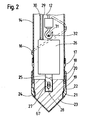
- the lower end of the steel tube 14 is shown in Figure 2. Over its entire length, the tube is surrounded by a concrete iron 16 wound helically around the tube and welded to the tube. At the end in- f érieure of the tube is removably fixed a ring 17 is screwed as shown in the drawing, or by keying if one wants to avoid the risk of unscrewing when removing the tube.
- This crown 17 carries a steel ring 18, free to rotate around the crown 17 and having an inner annular groove 19 by which it is retained axially on a heel 20 of the crown 17 with an axial clearance representing a certain working stroke.
- the ring 18 has at its reinforced lower part an inner surface 21 against which abuts a circular surface 22 of a pointed driving cone 23 whose conical part extends the conical end 24 of the ring 18.
- This driving cone 23 has an axial recess in which the striker 25 of a hydraulic hammer 26 engages, this striker being connected to the driving cone 23 by a key 27 passing through a lumen 28 of the striker 25.
- the hydraulic hammer 26, known per se, is fed through the tube 14 by two pipes 29 and 30. It is provided with a ring 31 by which it is suspended from a hook 2 fixed to the end of the cable 12.
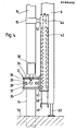
- FIGS 3 to 5 show the detail of the means for holding and rotating the tube 14.
- the rotating drive 13 comprises a ring 33 rotatably mounted between two brackets 34 and 35 by means of ball bearings.
- the ring 33 is provided with a ring gear 36 meshing with the pinion 37 of a hydraulic motor 38 carried by the console 34.
- the ring 33 carries eight small radial jacks 39 distributed around its circumference, jacks which serve to tighten the tube 14 for its rotational drive by the motor 38.
- the brackets 34 and 35 are integral with a vertical plate 40 connecting two vertical tubes 41 and 42 of square section provided, near their upper ends, rollers 43, respectively 44 , guiding the tubes 41 and 42 in two rails 45 and 46 welded along the first element 6 of the telescopic arm.
- the tubes 41 and 42 are mounted respectively around two hydraulic cylinders 47 and 48, the bodies of which are fixed to a cross-member 49 fixed to the inner end of the element 6 of the telescopic arm.
- the ends of the piston rods 50 and 51 of these cylinders are fixed to the respective upper ends of the tubes 41 and 42 which are closed for this purpose by a plate.
- the guide means 15 is constituted by a clamp fixed on a bar 52 connecting the tubes 41 and 42 near their upper end.
- the tubes 41 and 42 and the devices 13 and 15 therefore constitute a movable assembly capable of moving along the element 6 of the telescopic arm with a stroke equal to the stroke of the jacks 47 and 48.
- jacks also make it possible to lift the mobile assembly to release the tube 14 from the ground and to bring its end to the desired working height.
- the element 6 of the telescopic arm is further provided with a retractable foot 63, for example constituted by a jack, so that the telescopic arm can bear on the ground.
- FIGS. 6 to 11 The use of the installation will now be described in relation to FIGS. 6 to 11.
- the support and drive means for the tube shown in FIGS. 1 to 5 have not been shown in these figures. .
- the upper end of the tube 14 is closed by a cover 53 provided with a central hole for the passage of the cable 12 over which the cover can slide freely, the cable 12 being provided with a stop 54 making it possible to lift the cover when the cable 12 is pulled by means of the telescopic arm.
- This cover 53 is also traversed by the supply conduits 29 and 30 of the hydraulic hammer 26.
- the cover 53 further carries a curved pipe connection 55 at each end of which it is possible to fix a tube for supplying the concrete.
- the tube 14 In the position shown in FIG. 6, the tube 14 is sinking into the ground 56.
- the drive device 13 is first of all brought into its upper maximum position by means of the jacks 47 and 48.
- the hammer 26 strikes the driving cone 23 opening the way to the tube 14.
- the hits on the driving cone 23 must be transmitted to the crown 17.
- the tube is rotated by the device 13 and it sinks into the ground by screwing the propeller 16 into the walls of the hole drilled by the driving cone 23. If this driving cone 23 advances faster than the tube 14, the ring 18 arrives at the end of its travel on the crown 17 and the hammer 26 strikes are then transmitted to the tube 14. As soon as this occurs the operator momentarily stops the hammer 26 so as to allow the tube to descend.
- This stop could easily be automatically controlled by a detector fixed to the tube 14, for example on its inner face.
- the tube 14 has a practical and transportable length, for example, 7 meters.
- a practical and transportable length for example, 7 meters.
- the hammer 26 and the driving cone 23 are removed and a second identical tube 14 'is fixed to the tube 14 which is connected to the tube 14 by means of a ring 57 fixed by keys in a manner known per se.
- the tube 14 ′ is introduced into the devices 13 and 15, then the hammer 26 and its driving cone 23 are reintroduced to continue driving the tubes.
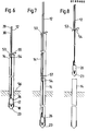
- a reinforcement 58 (FIG. 9) is fitted into the tube 14, by means of the same hook 32, provided with a sheet metal cone 64 of diameter substantially equal to the inside diameter of the tube. tube 14 and intended to expel the water likely to be in the tube. It should be noted that the tube 14, respectively the tube 14 ', always has a part protruding from the ground which is clamped in the device 13.
- the finished pile 65 is shown in FIG. 11.
- the installation is particularly intended for driving tubes with a diameter of 340 mm, the ring 18 having a diameter of 400 mm.
- the installation mounted on a vehicle is very mobile and is very quick to install.
- Using a hydraulic hammer striking a jacking cone has proven to be much better than existing threshing and drilling installations.
- the method and the installation also have the advantage of making it possible to prepare and fix a large length of assembled tubes, approximately 20 to 30 m, on the telescopic arm of the self-crane for the execution of the second pile and of the following piles on the same site, once the pile length has been established for this site.
- the hammer 26 and the driving cone 23 can be reintroduced into the tube assembly, by its lower end, simply by removing the ring 17, these maneuvers being easy to execute.
- the driving cone here consists of a cone 65 independent of the hydraulic hammer 26 and preferably of reinforced concrete for cost reasons.
- This cone has a base with a diameter slightly larger than the inside diameter of the ring 18 so that it cannot go back up into the tube 14.
- the cone 65 also comes to be housed in an internal flange 68 of the ring 18 in which it is retained and guided laterally.
- the hydraulic hammer is integral with a cylindrical striking head 66 corresponding to the upper half of the driving cone 23 in FIG. 2 and provided with a range 22 'identical to the range 22 of the strike 2. This strike head 66 therefore drives the ring 18 by its reach 21 and it is removed with the hydraulic hammer 26.
- the second solution consists in covering the driving cone 23 and the conical end 24 of the ring 18 with a conical steel cap 67 as shown in FIG. 2.
- This cap 67 is pressed in with the driving cone 23 and the tube 14 and then remains at the bottom of the hole, somehow closing the end of the tube and preventing sufficient rise of the water in the tube.
Abstract
Description
La présente invention a pour objet un procédé de construction d'un pieu de soutènement en béton armé consistant à enfoncer un tube en acier dans le sol et à le remplir de béton.The subject of the present invention is a method of constructing a reinforced concrete retaining pile which consists in driving a steel tube into the ground and filling it with concrete.
Il est connu d'enfoncer des pieux tubulaires en acier dans le sol par roto-percussion. A cet effet, on utilise une sonnette de battage pour battre l'extrémité du tube à laquelle on a préalablement fixé une pièce par vissage permettant de le battre et de l'entrainer simultanément en rotation pas à pas. La sonnette de battage représente une installation très lourde, de l'ordre de 30 à 40 tonnes, constituant un matériel important et coûteux, tant en ce qui concerne l'achat et l'amortissement que le transport. Pour amortir les frais de mise en place d'une telle installation il est nécessaire de construire un nombre de pieux relativement élevé au même endroit. Le tube en acier est en outre relativement très lourd, à parois épaisses, pour résister au battage et au flambage.It is known to drive tubular steel piles into the ground by rotary percussion. To this end, a threshing bell is used to beat the end of the tube to which a part has previously been fixed by screwing, making it possible to beat it and simultaneously drive it in step-by-step rotation. The threshing bell represents a very heavy installation, of the order of 30 to 40 tonnes, constituting an important and expensive material, both with regard to purchase and depreciation as well as transport. To amortize the costs of setting up such an installation, it is necessary to build a relatively large number of piles in the same place. The steel tube is also relatively very heavy, with thick walls, to resist beating and buckling.
On connait également des pieux en béton, système HW réalisés au moyen d'un tube de forage récupéré après l'injection de béton dans le tube. Le tube est entrainé en oscillation au moyen d'un dispositif d'entrainement placé sur la tête du tube et actionné à l'air comprimé. Cette méthode nécessite également un équipement relativement lourd et de hauteur supérieure à la longueur des plus longs tubes que l'on désire pouvoir enfoncer.Concrete piles are also known, HW system produced by means of a drill pipe recovered after the injection of concrete into the pipe. The tube is driven in oscillation by means of a driving device placed on the head of the tube and actuated with compressed air. This method also requires relatively heavy equipment and a height greater than the length of the longest tubes that it is desired to be able to drive.
Les procédés utilisant de grandes sonnettes ne sont pratiquement pas utilisables pour de petits chantiers, car il n'est pas possible d'amortir le coût de la mise en place de l'installation. Dans ce cas on a dès lors recours à des solutions de remplacement plus ou moins heureuses et souvent insuffisantes, telles que radiers ou autres.The processes using large bells are practically not usable for small sites, because it is not possible to amortize the cost of setting up the installation. In this case we therefore resort to more or less happy and often insufficient alternatives, such as rafts or others.
La présente invention a pour but de permettre la construction de pieux en béton au moyen d'une installation légère et très mobile, dont les frais de mise en place sont faibles, de telle sorte qu'elle puisse être utilisée de façon rentable sur des chantiers de moyenne et petite dimension. On a également cherché à simplifier le travail de l'opérateur et à réaliser un gain de temps dans la construction d'un pieu.The object of the present invention is to enable the construction of concrete piles by means of a light and very mobile installation, the installation costs of which are low, so that it can be used profitably on construction sites. medium and small. We also tried to simplify the operator's work and save time in the construction of a pile.
Le procédé selon invention est caractérisé en ce qu'on enfonce le tube d'une part en frappant au moyen d'un marteau hydraulique suspendu dans le tube, sur un cône de fonçage indépendant du tube et d'autre part en entrainant le tube en rotation, qu'on retire le cône de fonçage avec le marteau, une fois le tube enfoncé, qu'on introduit une armature dans le tube, qu'on coule du béton dans le tube en retirant progressivement le tube au fur et à mesure du remplissage du trou par le béton.The method according to the invention is characterized in that the tube is driven in on the one hand by striking by means of a hydraulic hammer suspended in the tube, on a driving cone independent of the tube and on the other hand by driving the tube in rotation, that we remove the jacketing cone with the hammer, once the tube is pressed, that we introduce a reinforcement in the tube, that we pour concrete in the tube by gradually withdrawing the tube as and when filling the hole with concrete.
Etant donné qu'on ne bat pas l'extrémité supérieure du tube, celui-ci n'a pas besoin de présenter une grande résistance. Il n'y a même pratiquement aucun choc sur le tube, étant donné que l'on frappe directement sur le cône de fonçage. Le marteau hydraulique et le cône de fonçage sont de faible volume, facilement transportables et pourtant d'une grande efficacité. L'entrainement en rotation du tube peut se faire en un point intermédiaire du tube situé à une faible hauteur au-dessus du sol, de telle sorte que l'équipement nécessaire peut être de dimensions réduites.Since the upper end of the tube is not beaten, it does not need to be very strong. There is hardly even any shock on the tube, since one strikes directly on the driving cone. The hydraulic hammer and the driving cone are small, easily trans portable and yet highly efficient. The rotational drive of the tube can be done at an intermediate point of the tube located at a low height above the ground, so that the necessary equipment can be reduced in size.
Le cône de fonçage peut être solidaire du marteau et réutilisable ou indépendant du marteau et laissé au fond du trou pour empêcher l'eau souterraine de remonter dans le trou.The jacking cone can be integral with the hammer and reusable or independent of the hammer and left at the bottom of the hole to prevent groundwater from going back into the hole.
Le procédé selon invention peut être mis en oeuvre avec des moyens légers, de préférence porté par un véhicule le tout étant agencé de telle sorte que toutes les opérations peuvent être faites au sol ou sur le véhicule.The method according to the invention can be implemented with light means, preferably carried by a vehicle, the whole being arranged so that all the operations can be carried out on the ground or on the vehicle.
L'invention a également pour objet une installation telle que définie par la revendication 6.The invention also relates to an installation as defined by
Le dessin annexé représente, à titre d'exemple, une forme d'exécution d'une installation selon l'invention.
- La figure 1 est une vue d'ensemble de l'installation montée sur un véhicule.
- La figure 2 est une vue en coupe axiale de l'extrémité inférieure du tube et du cône de fonçage.
- La figure 3 est une vue partielle de l'installation selon la direction A, figure 1.
- La figure 4 est une vue de côté de la même partie de l'installation.
- La figure 5 est une vue en coupe selon V-V de la figure 3.
- Les figures 6 à 11 représentent diverses phases de la construction d'un pieu.
- La figure 12 représente une variante d'exécution du cône de fonçage.
- Figure 1 is an overview of the installation mounted on a vehicle.
- Figure 2 is an axial sectional view of the lower end of the tube and the driving cone.
- FIG. 3 is a partial view of the installation in direction A, FIG. 1.
- Figure 4 is a side view of the same part of the installation.
- FIG. 5 is a sectional view along VV of FIG. 3.
- Figures 6 to 11 show various stages in the construction of a stake.
- Figure 12 shows an alternative embodiment of the driving cone.
La figure 1 représente schématiquement un véhicule 1 sur lequel est montée l'installation. Ce véhicule est de type connu. Ses quatre roues sont orientables et il est muni de quatre pieds tels que 2 et 3, montés sur vérin, pour soutenir le véhicule en position de travail. Il comporte une tourelle centrale 4 portant un bras 5 à l'extrémité duquel est articulé le premier élément 6 d'un bras télescopique comprenant en outre deux autres bras 7 et 8 constituant une grue télescopique. La tourelle 4 porte en outre un vérin télescopique 9 dont l'extrémité est articulée au bras télescopique 6 pour le redresser en position verticale. respectivement pour le ramener en position horizontale sur un support 10. L'élément 8 du bras télescopique est muni d'une tête 11 à laquelle est attaché un câble 12.FIG. 1 schematically represents a vehicle 1 on which the installation is mounted. This vehicle is of known type. Its four wheels are steerable and it is provided with four feet such as 2 and 3, mounted on a jack, to support the vehicle in the working position. It comprises a
Le premier élément 6 du bras télescopique porte en outre un dispositif 13 pour l'entrainement en rotation du tube 14 et un dispositif 15 de maintien et de guidage du tube. Les dispositifs 13 et 15 peuvent se déplacer avec une certaine course sur l'élément 6, comme ceci sera décrit plus loin en relation avec les figures 3 à 5.The
L'extrémité inférieure du tube en acier 14 est représentée à la figure 2. Sur toute sa longueur, le tube est entouré d'un fer à béton 16 enroulé en hélice autour du tube et soudé sur le tube. A l'extrémité in- férieure du tube est fixée amoviblement une couronne 17 soit par vissage comme représenté au dessin, ou par clavetage si l'on veut éviter un risque de dévissage lors du retrait du tube. Cette couronne 17 porte un anneau en acier 18, libre en rotation autour de la couronne 17 et présentant une rainure annulaire intérieure 19 par laquelle elle est retenue axialement sur un talon 20 de la couronne 17 avec un jeu axial représentant une certaine course de travail. L'anneau 18 présente à sa partie inférieure renforcée une portée intérieure 21 contre laquelle vient buter une portée circulaire 22 d'un cône de fonçage pointu 23 dont la partie conique prolonge l'extrémité cônique 24 de l'anneau 18. Ce cône de fonçage 23 présente une creusure axiale dans laquelle s'engage le percuteur 25 d'un marteau hydraulique 26, ce percuteur étant relié au cône de fonçage 23 par une clavette 27 traversant une lumière 28 du percuteur 25. Le marteau hydraulique 26, connu en soi, est alimenté à travers le tube 14 par deux conduites 29 et 30. Il est muni d'un anneau 31 par lequel il est suspendu à un crochet 2 fixé à l'extrémité du câble 12.The lower end of the
Les figures 3 à 5 représentent le détail des moyens de maintien et d'entrainement en rotation du tube 14. Le dispositif d'entrainement en rotation 13 comprend un anneau 33 monté rotativement entre deux consoles 34 et 35 au moyen de roulements à billes. L'anneau 33 est muni d'une couronne dentée 36 engrenant avec le pignon 37 d'un moteur hydraulique 38 porté par la console 34. L'anneau 33 porte huit petits vérins radiaux 39 répartis sur sa circonférence, vérins qui servent à serrer le tube 14 pour son entrainement en rotation par le moteur 38. Les consoles 34 et 35 sont solidaires d'une plaque verticale 40 reliant deux tubes verticaux 41 et 42 de section carrée munis, près de leurs extrémités supérieures, de galets 43, respectivement 44, guidant les tubes 41 et 42 dans deux rails 45 et 46 soudés le long du premier élément 6 du bras télescopique. Les tubes 41 et 42 sont montés respectivement autour de deux vérins hydrauliques 47 et 48 dont les corps sont fixés sur une traverse 49 fixée à l'extrémité intérieure de l'élément 6 du bras télescopique. Les extrémités des tiges de pistons 50 et 51 de ces vérins sont fixés aux extrémités supérieures respectives des tubes 41 et 42 qui sont à cet effet fermés par une plaque. Le moyen de guidage 15 est constitué par une pince fixée sur une barre 52 reliant les tubes 41 et 42 près de leur extrémité supérieure. Les tubes 41 et 42 et les dispositifs 13 et 15 constituent dès lors un équipage mobile susceptible de se déplacer le long de l'élément 6 du bras télescopique avec une course égale à la course des vérins 47 et 48. Ces vérins permettent en outre de soulever l'équipage mobile pour dégager le tube 14 du sol et pour amener son extrémité à la hauteur de travail désirée. L'élément 6 du bras télescopique est en outre muni d'un pied rétractable 63, par exemple constitué par un vérin, pour que le bras télescopique puisse prendre appui sur le sol.Figures 3 to 5 show the detail of the means for holding and rotating the
L'utilisation de l'installation sera décrite maintenant en relation avec les figures 6 à 11. Dans un souci de simplification, on n'a pas représenté dans ces figures les moyens de soutien et d'entrainement du tube représenté aux figures 1 à 5.The use of the installation will now be described in relation to FIGS. 6 to 11. For the sake of simplification, the support and drive means for the tube shown in FIGS. 1 to 5 have not been shown in these figures. .
En se référant à la figure 6, il convient encore d'ajouter que l'extrémité supérieure du tube 14 est fermée par un couvercle 53 muni d'un trou central pour le passage du câble 12 sur lequel le couvercle peut coulisser librement, le câble 12 étant muni d'un arrêt 54 permettant de soulever le couvercle lorsqu'on tire le câble 12 au moyen du bras télescopique. Ce couvercle 53 est également traversé par les conduits d'alimentation 29 et 30 du marteau hydraulique 26. Le couvercle 53 porte en outre un raccord de tuyau recourbé 55 à chaque extrémité duquel il est possible de fixer un tube pour l'amenée du béton.Referring to Figure 6, it should also be added that the upper end of the
Dans la position représenté à la figure 6, le tube 14 est en train de s'enfoncer dans le sol 56. Le dispositif d'entrainement 13 est tout d'abord amené dans sa position maximale supérieure au moyen des vérins 47 et 48. Le marteau 26 frappe sur le cône de fonçage 23 ouvrant le chemin au tube 14. Les coups sur le cône de fonçage 23 doivent être transmis à la couronne 17. Simultanément, le tube est entrainé en rotation par le dispositif 13 et il s'enfonce dans le sol par vissage de l'hélice 16 dans les parois du trou foré par le cône de fonçage 23. Si ce cône de fonçage 23 avance plus rapidement que le tube 14, l'anneau 18 arrive en bout de course sur la couronne 17 et les coups du marteau 26 sont alors transmis au tube 14. Dès que cela se produit l'opérateur arrête momentanément le marteau 26 de manière à permettre au tube de descendre. Cet arrêt pourrait être facilement commandé automatiquement par un détecteur fixé sur le tube 14, par exemple sur sa face intérieure. Lorsque le tube est descendu de la valeur de la course de ces vérins, les dispositifs 13 et 15 sont desserrés et ramenés dans leur position maximale supérieure, dans laquelle ils sont resserrés pour une nouvelle course et ainsi de suite.In the position shown in FIG. 6, the
Le tube 14 présente une longueur pratique et transportable, par exemple, 7 mètres. A la figure 7, on a considéré le cas dans lequel on désire construire un pieu en béton d'une longueur supérieure à 7 mètres. Dans ce cas, après avoir presque totalement enfoncé le tube 14, on retire le marteau 26 et le cône de fonçage 23 et l'on fixe au tube 14 un second tube identique 14' que l'on relie au tube 14 au moyen d'une bague 57 fixée par des clavettes de façon connu en soi. Le tube 14' est introduit dans les dispositifs 13 et 15, puis on réintroduit le marteau 26 et son cône de fonçage 23 pour poursuivre l'enfoncement des tubes.The
Une fois que l'on a atteint la profondeur désirée, on retire le marteau 26 et son cône de fonçage, comme représenté à la figure 8.Once the desired depth has been reached, the
On décroche ensuite le marteau 26 et l'on introduit dans le tube 14, au moyen du même crochet 32, une armature 58 (figure 9) munie à son extrémité inférieure d'un cône en tôle 64 de diamètre sensiblement égal au diamètre intérieur du tube 14 et destiné à chasser l'eau susceptible de se trouver dans le tube. Il convient de noter que le tube 14, respectivement le tube 14', présente toujours une partie dépassant le sol qui est serrée dans le dispositif 13.Then the
On relève ensuite le crochet 32 pour y suspendre un vibreur hydraulique 59 alimenté par les conduits 29 et 30 (figure 10). On fixe en outre au raccord 55 un tuyau vertical 60 et un tuyau d'alimentation 61 reliés à une installation de propulsion de béton. Il convient de souligner que toutes les opérations d'accrochage de dispositifs au crochet 32 et de raccordement des tuyaux 60 et 61 peuvent être effectuées au sol à côté du tube enfoncé 14, ceci grâce à la tourelle 4. On introduit ensuite le vibreur 59 et le tube 60 dans le tube 14 et on remplit le trou de béton 62 tout en retirant le tube 14 par un mouvement de traction et de dévissage assuré d'une part par les vérins 47 et 48 et, d'autre part, par l'anneau 33 entraîné dans le sens inverse de celui de la figure 6, comme indiqué par les flèches. Le tube 14 est retiré au fur et à mesure du remplissage du trou par le béton, de telle sorte que le trou est parfaitement rempli d'un béton compact vibré.Then raise the
Le pieu terminé 65 est représenté à la figure 11. Dans cette figure, on voit également qu'il est possible de maintenir le tube 14 à la hauteur de travail la plus commode pour effectuer toutes opérations à la partie inférieure du tube, par exemple enlever la couronne 17, enlever le vibrateur hydraulique, remonter le marteau hydraulique et son cône au câble se trouvant à l'intérieur du tube 14 et le soulever suffisamment pour refi- xer la couronne 17. Après ces opérations l'installation est prête pour le pieu suivant.The
L'installation est particulièrement prévue pour enfoncer des tubes d'un diamètre de 340 mm, l'anneau 18 présentant un diamètre de 400 mm.The installation is particularly intended for driving tubes with a diameter of 340 mm, the
L'installation montée sur véhicule est d'une grande mobilité est d'une mise en place très rapide. L'utilisation d'un marteau hydraulique frappant sur un cône de fonçage s'est avérée être d'un rendement bien supérieur aux installations de battage et forage existantes.The installation mounted on a vehicle is very mobile and is very quick to install. Using a hydraulic hammer striking a jacking cone has proven to be much better than existing threshing and drilling installations.
Le procédé et l'installation ont en outre l'avantage de permettre de préparer et de fixer une grande longueur de tubes assemblés, environ 20 à 30 m, sur le bras télescopique de l'auto-grue pour l'exécution du deuxième pieu et des pieux suivants sur un même chantier, une fois la longueur des pieux établie pour ce chantier. Le marteau 26 et le cône de fonçage 23 peuvent être réintroduits dans l'assemblage de tubes, par son extrémité inférieure, simplement en enlevant l'anneau 17, ces manoeuvres étant faciles à exécuter.The method and the installation also have the advantage of making it possible to prepare and fix a large length of assembled tubes, approximately 20 to 30 m, on the telescopic arm of the self-crane for the execution of the second pile and of the following piles on the same site, once the pile length has been established for this site. The
Dans certains sols, il arrive fréquemment que l'eau souterraine ou l'eau d'infiltration remonte dans le tube enfoncé lorsqu'on retire le cône de fonçage et avant que l'on introduise l'armature 58 munie de son cône 64. Deux solutions ont été retenues pour empêcher ce phénomène.In certain soils, it often happens that the ground water or the infiltration water rises in the pressed tube when the jacking cone is removed and before the
La première solution est représentée à la figure 12. Le cône de fonçage est constitué ici par un cône 65 indépendant du marteau hydraulique 26 et de préférence en béton armé pour des raisons de coût. Ce cône présente une base de diamètre légèrement plus grand que le diamètre intérieur de l'anneau 18 de telle sorte qu'il ne puisse pas remonter dans le tube 14. Le cône 65 vient en outre se loger dans une battue intérieure 68 de l'anneau 18 dans laquelle il est retenu et guidé latéralement. Le marteau hydraulique est solidaire d'une tête de frappe cylindrique 66 correspondant à la moitié supérieure du cône de fonçage 23 de la figure 2 et munie d'une portée 22' identique à la portée 22 de la frappe 2. Cette tête de frappe 66 entraine donc l'anneau 18 par sa portée 21 et elle est retirée avec le marteau hydraulique 26.The first solution is shown in Figure 12. The driving cone here consists of a
La seconde solution consiste à recouvrir le cône de fonçage 23 et l'extrémité conique 24 de l'anneau 18 d'une cape conique en acier 67 comme représenté à la figure 2. Cette cape 67 est enfoncée avec le cône de fonçage 23 et le tube 14 et reste ensuite au fond du trou, fermant en quelque sorte l'extrémité du tube et empêchant dans une mesure suffisante une remontée de l'eau dans le tube.The second solution consists in covering the driving
Dans les deux cas le cône 64 de l'armature peut être supprimé.In both cases the
Claims (15)
Applications Claiming Priority (2)
| Application Number | Priority Date | Filing Date | Title |
|---|---|---|---|
| CH5196/84 | 1984-10-31 | ||
| CH519684 | 1984-10-31 |
Publications (1)
| Publication Number | Publication Date |
|---|---|
| EP0185402A1 true EP0185402A1 (en) | 1986-06-25 |
Family
ID=4289543
Family Applications (1)
| Application Number | Title | Priority Date | Filing Date |
|---|---|---|---|
| EP19850201767 Withdrawn EP0185402A1 (en) | 1984-10-31 | 1985-10-31 | Method for constructing a concrete pile and device for the application of the method |
Country Status (1)
| Country | Link |
|---|---|
| EP (1) | EP0185402A1 (en) |
Cited By (7)
| Publication number | Priority date | Publication date | Assignee | Title |
|---|---|---|---|---|
| GB2250047A (en) * | 1990-11-22 | 1992-05-27 | Bicc Plc | Foundation piling |
| EP0598457A1 (en) * | 1992-11-18 | 1994-05-25 | Beton Son B.V. | Method for providing a foundation pile in the ground without vibration, and apparatus for applying such method |
| EP0687777A1 (en) * | 1994-06-16 | 1995-12-20 | Heiwerken P. van 't Wout Waddinxveen B.V. | Method for arranging concrete piles in the ground |
| GB2372517A (en) * | 2001-02-21 | 2002-08-28 | Roxbury Ltd | Particulate ground columns |
| ITVI20110203A1 (en) * | 2011-07-27 | 2013-01-28 | Massimo Barin | MATRIX FOR THE CONSTRUCTION OF OUTDOOR POLES FOR FOUNDATIONS AND METHOD FOR THE REALIZATION OF UNDERGROUND POLES USING THIS MATRIX |
| US8602689B1 (en) * | 2011-06-03 | 2013-12-10 | Heli-Crete “Eco-Friendly” Piling Systems, Llc | Retractable nose cone system and method for forming reinforced concrete pilings and/or an electrical grounding system |
| CN106627825A (en) * | 2016-07-27 | 2017-05-10 | 黄运新 | Breach blocking robot |
Citations (11)
| Publication number | Priority date | Publication date | Assignee | Title |
|---|---|---|---|---|
| NL88487C (en) * | 1900-01-01 | |||
| GB504244A (en) * | 1938-07-18 | 1939-04-21 | Gino Adriano Garzi | Apparatus for driving into the ground boring tubes and moulds for building wells, erecting concrete piles and the like |
| FR1087358A (en) * | 1953-07-24 | 1955-02-23 | Method and device for driving foundation piles | |
| DE1131157B (en) * | 1952-08-01 | 1962-06-07 | Demag Ag | Device for driving in a concrete pile tip, intended for in-situ concrete foundation piles and remaining in the ground, with a post pipe that follows |
| GB1162014A (en) * | 1966-11-14 | 1969-08-20 | Andre Charles A Vanlandschoote | Improvements in or relating to Concrete Foundation Piles |
| CH481277A (en) * | 1968-07-26 | 1969-11-15 | Rombaldi Albert | Device for driving a concrete pile |
| FR2056654A5 (en) * | 1969-08-14 | 1971-05-14 | Casagrande Antonio | |
| DE1634245B1 (en) * | 1965-05-18 | 1971-08-12 | Bbc Brown Boveri & Cie | Device for pulling a driving pipe used for the production of in-situ concrete piles |
| DE2645071A1 (en) * | 1976-10-06 | 1978-04-13 | Bbc Brown Boveri & Cie | Mobile pile-driver with adjustable and swivelable impacter - has impacter support with telescopic hydraulic cylinders to move driver ram to vertical operating position |
| DE3211471A1 (en) * | 1982-03-29 | 1983-10-06 | Klaus Dipl Ing Jourdan | Method of relieving the drill-head mounting when sinking a drill pipe, as well as a device for carrying out the method |
| NL8401436A (en) * | 1984-05-04 | 1984-07-02 | Bredero Nv | Foundation pile positioning system - comprises delivering water below spiral blades to loosen earth whilst introducing hardening grout |
-
1985
- 1985-10-31 EP EP19850201767 patent/EP0185402A1/en not_active Withdrawn
Patent Citations (11)
| Publication number | Priority date | Publication date | Assignee | Title |
|---|---|---|---|---|
| NL88487C (en) * | 1900-01-01 | |||
| GB504244A (en) * | 1938-07-18 | 1939-04-21 | Gino Adriano Garzi | Apparatus for driving into the ground boring tubes and moulds for building wells, erecting concrete piles and the like |
| DE1131157B (en) * | 1952-08-01 | 1962-06-07 | Demag Ag | Device for driving in a concrete pile tip, intended for in-situ concrete foundation piles and remaining in the ground, with a post pipe that follows |
| FR1087358A (en) * | 1953-07-24 | 1955-02-23 | Method and device for driving foundation piles | |
| DE1634245B1 (en) * | 1965-05-18 | 1971-08-12 | Bbc Brown Boveri & Cie | Device for pulling a driving pipe used for the production of in-situ concrete piles |
| GB1162014A (en) * | 1966-11-14 | 1969-08-20 | Andre Charles A Vanlandschoote | Improvements in or relating to Concrete Foundation Piles |
| CH481277A (en) * | 1968-07-26 | 1969-11-15 | Rombaldi Albert | Device for driving a concrete pile |
| FR2056654A5 (en) * | 1969-08-14 | 1971-05-14 | Casagrande Antonio | |
| DE2645071A1 (en) * | 1976-10-06 | 1978-04-13 | Bbc Brown Boveri & Cie | Mobile pile-driver with adjustable and swivelable impacter - has impacter support with telescopic hydraulic cylinders to move driver ram to vertical operating position |
| DE3211471A1 (en) * | 1982-03-29 | 1983-10-06 | Klaus Dipl Ing Jourdan | Method of relieving the drill-head mounting when sinking a drill pipe, as well as a device for carrying out the method |
| NL8401436A (en) * | 1984-05-04 | 1984-07-02 | Bredero Nv | Foundation pile positioning system - comprises delivering water below spiral blades to loosen earth whilst introducing hardening grout |
Cited By (10)
| Publication number | Priority date | Publication date | Assignee | Title |
|---|---|---|---|---|
| GB2250047A (en) * | 1990-11-22 | 1992-05-27 | Bicc Plc | Foundation piling |
| EP0598457A1 (en) * | 1992-11-18 | 1994-05-25 | Beton Son B.V. | Method for providing a foundation pile in the ground without vibration, and apparatus for applying such method |
| EP0687777A1 (en) * | 1994-06-16 | 1995-12-20 | Heiwerken P. van 't Wout Waddinxveen B.V. | Method for arranging concrete piles in the ground |
| NL9400987A (en) * | 1994-06-16 | 1996-02-01 | Heiwerken P Van T Wout Waddinx | Method for installing concrete piles in the ground. |
| GB2372517A (en) * | 2001-02-21 | 2002-08-28 | Roxbury Ltd | Particulate ground columns |
| GB2372517B (en) * | 2001-02-21 | 2004-08-11 | Roxbury Ltd | Particulate ground columns |
| US8602689B1 (en) * | 2011-06-03 | 2013-12-10 | Heli-Crete “Eco-Friendly” Piling Systems, Llc | Retractable nose cone system and method for forming reinforced concrete pilings and/or an electrical grounding system |
| US9512589B1 (en) | 2011-06-03 | 2016-12-06 | Heli-Crete Eco-Friendly Piling Systems, Llc | Retractable nose cone system and method for forming reinforced concrete pilings and/or an electrical grounding system |
| ITVI20110203A1 (en) * | 2011-07-27 | 2013-01-28 | Massimo Barin | MATRIX FOR THE CONSTRUCTION OF OUTDOOR POLES FOR FOUNDATIONS AND METHOD FOR THE REALIZATION OF UNDERGROUND POLES USING THIS MATRIX |
| CN106627825A (en) * | 2016-07-27 | 2017-05-10 | 黄运新 | Breach blocking robot |
Similar Documents
| Publication | Publication Date | Title |
|---|---|---|
| EP0265344B1 (en) | Method for producting a pile in the ground, drilling machine and device for carrying out such a method | |
| ES2388645T3 (en) | Drilling device and drilling procedure | |
| EP1605242B1 (en) | System for the use of an apparatus for taking samples in the ground or a granular or pulverulent material | |
| FR2563861A1 (en) | DEVICE FOR CLEANING TARRIES. | |
| JP2003193785A (en) | Boring device and method | |
| FR2566813A1 (en) | Device and method for producing concrete piles in the ground and piles obtained by this method | |
| EP0185402A1 (en) | Method for constructing a concrete pile and device for the application of the method | |
| CN112096281B (en) | Drilling, pile splicing and pile planting all-in-one machine and construction method thereof | |
| JP5670282B2 (en) | Excavator and method for forming excavation hole | |
| CA1317604C (en) | Device for evacuating excavated material for making deep tranches | |
| FR2752857A1 (en) | APPARATUS FOR HOLLOWING IN THE SOIL OF VERY DEPTH TRENCHES | |
| CN212772357U (en) | Hole cleaning device for prestressed concrete pipe pile | |
| BE887882A (en) | STRUCTURE FOR SUPPORTING APPARATUS ABOVE THE BOTTOM OF A MASS OF WATER | |
| EP0114146B1 (en) | Universal drilling apparatus equipped with means for rapid raising of the drill string | |
| EP0592326B1 (en) | Trenching apparatus for digging deep trenches with cutting drums | |
| EP2900875B1 (en) | Method of making a foundation | |
| FR2757273A1 (en) | BASEMENT RECOGNITION DEVICE | |
| JP3589921B2 (en) | Piling device | |
| EP0131562B1 (en) | Method for casting piles by means of a drive-out screw | |
| JP2002004280A (en) | High toque rotary press in auger | |
| FR2478158A1 (en) | Round hollow section self-boring pile - uses spiral ramped cutters on leading edge and used as fence post or cable-anchor | |
| JP2950727B2 (en) | Underground pipe laying equipment | |
| BE699657A (en) | ||
| FR2745031A1 (en) | Rotary percussion tool for drilling large-diameter wells in very hard ground | |
| BE496140A (en) |
Legal Events
| Date | Code | Title | Description |
|---|---|---|---|
| PUAI | Public reference made under article 153(3) epc to a published international application that has entered the european phase |
Free format text: ORIGINAL CODE: 0009012 |
|
| AK | Designated contracting states |
Kind code of ref document: A1 Designated state(s): AT BE CH DE FR GB IT LI NL SE |
|
| 17P | Request for examination filed |
Effective date: 19861201 |
|
| 17Q | First examination report despatched |
Effective date: 19880120 |
|
| STAA | Information on the status of an ep patent application or granted ep patent |
Free format text: STATUS: THE APPLICATION IS DEEMED TO BE WITHDRAWN |
|
| 18D | Application deemed to be withdrawn |
Effective date: 19890124 |