EP0184819B1 - Apparatus and process for carbon black production - Google Patents
Apparatus and process for carbon black production Download PDFInfo
- Publication number
- EP0184819B1 EP0184819B1 EP85115688A EP85115688A EP0184819B1 EP 0184819 B1 EP0184819 B1 EP 0184819B1 EP 85115688 A EP85115688 A EP 85115688A EP 85115688 A EP85115688 A EP 85115688A EP 0184819 B1 EP0184819 B1 EP 0184819B1
- Authority
- EP
- European Patent Office
- Prior art keywords
- tubular member
- reactor
- carbon black
- upstream
- oxidant gas
- Prior art date
- Legal status (The legal status is an assumption and is not a legal conclusion. Google has not performed a legal analysis and makes no representation as to the accuracy of the status listed.)
- Expired - Lifetime
Links
Images
Classifications
-
- C—CHEMISTRY; METALLURGY
- C09—DYES; PAINTS; POLISHES; NATURAL RESINS; ADHESIVES; COMPOSITIONS NOT OTHERWISE PROVIDED FOR; APPLICATIONS OF MATERIALS NOT OTHERWISE PROVIDED FOR
- C09C—TREATMENT OF INORGANIC MATERIALS, OTHER THAN FIBROUS FILLERS, TO ENHANCE THEIR PIGMENTING OR FILLING PROPERTIES ; PREPARATION OF CARBON BLACK ; PREPARATION OF INORGANIC MATERIALS WHICH ARE NO SINGLE CHEMICAL COMPOUNDS AND WHICH ARE MAINLY USED AS PIGMENTS OR FILLERS
- C09C1/00—Treatment of specific inorganic materials other than fibrous fillers; Preparation of carbon black
- C09C1/44—Carbon
- C09C1/48—Carbon black
- C09C1/50—Furnace black ; Preparation thereof
Definitions
- the invention relates to a gas distributor. In another aspect, the invention relates to a carbon black reactor. In yet another aspect, the invention relates to a process for producing carbon black.
- Newer generation reactors utilize axial air entry and have the capabilities of utilizing either or both axial and radial oil entries.
- An advantage of the newer reactors is their ability to produce low grit content carbon black.
- a problem encountered in scale up of small reactors to large ones is that of poor air distribution at the upstream end of the reactor. Poor air distribution can cause unstable combustion and will usually lead to poor predictability of resultant product properties.
- An air distributor for an axial flow reactor which is easy to scale up and adapt to any size reactor and provides stable combustion would clearly be very desirable.
- a carbon black reactor in one aspect of the invention, there is provided a carbon black reactor.
- the reactor has a precombustion zone having a first end and a second end for the combustion of a fuel with an oxidant gas to form hot gases having a temperature sufficiently high to decompose a carbonacous feedstock to form carbon black.
- the precombustion zone is refractory lined to withstand the high temperatures generated by the combustion process.
- a first tubular member extends upstream from the upstream end of the precombustion zone.
- the first tubular member has a longitudinal axis coaxially positioned with respect to the longitudinal axis of the precombustion zone, a first end and a second end. The second end of the first tubular member is positioned adjacent to the first end of the precombustion zone.
- the first tubular member preferably has an inside diameter which is similar to the inside diameter of the precombustion zone so that gas velocities between the inside of the first tubular member and the precombustion zone will not vary greatly.
- a second tubular member is provided which surrounds the first tubular member. An annulus is defined between an outside diameter of the first tubular member and the inside diameter of the second tubular member.
- the second tubular member is coaxially positioned with respect to the longitudinal axis of the precombustion zone.
- the second tubular member has a first end and a second end. The second end of the second tubular member is positioned adjacent to the first end of the precombustion zone.
- a closure is attached to the second end of the second tubular member.
- the closure is spaced apart from the second end of the first tubular member so as to define a fluid flow path.
- At least one tunnel opens through the second tubular member into the annulus between the first tubular member and the second tubular member in a generally radially inward direction toward the longitudinal axis of the precombustion zone.
- the longitudinal position at which the tunnel opens into the annulus is such that it falls between the first end of the first tubular member and the second end of the first tubular member.
- the reactor is operated for carbon black production.
- a stream of oxidant gas is flowed radially inwardly toward the longitudinal axis of a reactor having a longitudinal axis, an upstream end, and a downstream end.
- the oxidant gas is flowed into an annulus coaxially positioned with respect to the longitudinal axis of the reactor.
- the oxidant gas is then flowed in an upstream direction along the annulus to the upstream end of the reactor and then generally radially inwardly from the annulus at the upstream end of the reactor.
- the oxidant gas then follows a path having a generally circular cross section from the upstream end of the reactor to the downstream end of the reactor.
- a fuel is introduced into the stream of oxidant gas as it flows toward the downstream end of the reactor and combusted therewith to form hot gases having a temperature sufficiently high to decompose a carbonaceous feedstock and form carbon black.
- a carbonaceous feedstock is subsequently introduced into the hot gases resulting in its decomposition and the formation of carbon black which is subsequently collected.
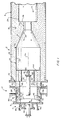
- FIGURE 1 is a sectional view of a portion of an apparatus embodying certain features of the present invention.
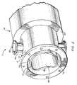
- FIGURE 2 is a pictorial representation of a device shown in cross-sectional view in FIGURE 1 with a portion thereof being removed to shown internal details.
- a carbon black reactor 2 has an upstream end 4 determined by an upstream end wall closure 6 and downstream end 8 determined by the location of a quench inlet 10 for the introduction of a pre-quench fluid to terminate the carbon forming reaction.
- the reactor 2 comprises, from upstream to downstream, an oxidant gas distributor section 12 which can be formed from a metal such as steel, a generally cylindrical precombustion zone 14, and a pyrolysis zone 16 having a generally circular cross section.
- the pyrolysis zone 16 is formed from a sidewall determining a generally frustoconical converging section 18 having radially inwardly directed oil ports 20 opening through the sidewall, a generally cylindrical reactor throat 22, and a generally cylindrical reactor zone 24.
- abrupt expansion 26 in the reaction flow passage connects the throat 22 with the reaction section 24.
- the generally cylindrical combustion zone 14 is preferably lined with a refractory material 28 to resist the high temperatures involved where fuel is combusted with an oxidant gas to form hot gases having a temperature sufficiently high to decompose a carbonaceous feedstock and form carbon black.
- the generally cylindrical precombustion zone has a first upstream end 30, a second downstream end 32 and a longitudinal axis 34 which coincides preferably with a longitudinal axis of the reaction zone 24 and the hereinafter described distributor 12.
- a first tubular member 36 extends toward the upstream end 4 of the reactor from the upstream first end 30 of the precombustion zone 14.
- the first tubular member 36 has a longitudinal axis preferably coaxially positioned with respect to the longitudinal axis 34 of the precombustion zone.
- the first tubular member 36 has a first end 38 and a second end 40.
- the second end 40 is preferably positioned adjacent to the first end 30 of the precombustion zone 14.
- the tubular member 36 is connected to the precombustion zone 14 via a short refractory section 42 having a generally cylindrical inside surface 44 corresponding to an inside surface 46 of the tubular member 36.
- the diameter determined by the inside surfaces 46 and 44 is preferably similar to the inside diameter defined by an inside surface 48 of the generally cylindrical precombustion zone 14.
- the diameter determined by the surface 46 will be in the range of from 50 to 200 percent of the diameter determined by the surface 48, usually in the range of from 75 to 150 percent of the diameter determined by surface 48, preferably from 75 to 125 percent of the diameter determined by the surface 48.
- a second tubular member 50 surrounds the first tubular member 36.
- the second tubular member 50 has an inside surface 52 which forms an annulus with respect to the outside surface 54 of the first tubular member 36.
- the second tubular member 50 has a longitudinal axis which is positioned coaxially with respect to the longitudinal axis 34 the precombustion zone 14.
- the second tubular member 50 has a first end 56 and a second end 57. The first end 56 is preferably positioned adjacent to the first end 30 of the precombustion zone 14.
- a closure 58 is attached to the second end 57 of the second tubular member 50.
- the closure 58 is spaced apart from the first end 38 of the first tubular member 36.
- fittings for pipe sight glasses 60 and 62 can be provided in closure 58 as well as a fitting 64 for the receipt of hereinafter described gas and oil tubes.
- At least one tunnel 66 opens through the second tubular member 50 into an annulus 68 defined between the outside surface 54, of the first tubular member 36 and the inside surface 52 of the second tubular member 50.
- Each tunnel 66 can be defined by a tubular member 69 which is connected to the second tubular member 50.
- Each tunnel 66 opens into the annulus at a longitudinal position which falls between the first end 38 and the second end 40 of the first tubular member 36.
- the annulus 68 commences at the upstream end of the refractory material defining the hot section of the reactor.
- a support spider formed from brackets 70 can position the first tubular member 36 in the second tubular member 50.
- the first tubular member 36 slides in the support spider to allow for temperature expansion.
- a plurality of tunnels 66 preferably open into the annulus 68 through the wall of the second tubular member 50.
- Each of the tunnels opens into the annulus at a longitudinal position falling between the first end 38 and the second end 40 of the first tubular member 36.
- each tunnel 66 is generally circumferentially equally spaced from each of the other tunnels.
- two tunnels 66 which are opposed to each other are used because two tunnels have been used with good results.
- the first end 38 of the first tubular member 36 can be provided with cutouts or scallops or, in the case of two tunnels 66, a saddle 72.
- the cutout is circumferentially oriented or offset with respect to each tunnel 66 so that the maximum depth of the cutout or scallop falls between the center lines of the tunnels 66, when viewed from the perspective of the point of intersection of the longitudinal axis of the reactor and the closure 58. This perspective point is called out by the reference numeral 74 in FIGURE 1.
- Fuel and make oil can be introduced into the reactor 2 through the end wall 58 via the fitting 64.
- an axial tube 76 for the introduction of fuel extends through the closure 58 and empties into the precombustion zone 14.
- the end of the tube 76 is preferably closed by plate 78 forming a flange 80 on the end of the tubular member 76 and the fuel is emitted upstream of the flange 80 through radially outwardly directed apertures 82.
- the precombustion zone 14 is provided with a choke section 84 formed from a refractory material which is positioned adjacent to the first end 30 of the precombustion zone 14.
- the apertures 82 in the fuel gas tube open into the reactor at a longitudinal position which is spaced radially inward from choke 84.
- an oil tube 86 can be coaxially positioned within the gas tube 76. The oil tube can protrude from the downstream end of the gas tube 76 as determined by the flange 80 well into the precombustion zone 14 if desired.
- a process for producing carbon black In the process, a stream of oxidant gas is flowed radially inward toward the longitudinal axis of the reactor having longitudinal axis, an upstream end and a downstream end. The gas is flowed into an annulus, such the annulus 68 from a radially inward path such as determined by the tunnel 66. The annulus 68 is coaxially positioned with respect to the longitudinal axis of the reactor. The oxidant gas is then flowed in an upstream direction with respect to the downstream end of the reactor along a generally annular flow path to the upstream end of the reactor.
- the oxidant gas is flowed generally radially inwardly from the annulus and into a flow path of generally circular cross section extending from the upstream end of the reactor to the downstream end such as from upstream end 6 to downstream end 8 of the reactor 2.
- a combustible fuel can be introduced into the stream of oxidant gas as it flows toward the downstream end of the reactor for combustion with the oxidant gas to form hot gases having a temperature sufficiently high to decompose a carbonaceous feedstock to form carbon black.
- such combustion would occur in a precombustion zone such as a refractory-lined zone 14.
- a carbonaceous feedstock can then be introduced into the hot gases and the carbon black formed by the resultant decomposition can be collected as is conventionally known in the art after being quenched to below carbon forming temperature such as by quench fluid, steam or the like, introduced into the reaction flow path via the ports 10.
- the fluid distributor 12 is sufficiently separated from the combustion process, it can be relatively inexpensively formed from a suitable metal such as steel. It is therefore preferable that the combustion of fuel with oxidant gas occur downstream of the point where the oxidant gases are brought radially inward into the annular flow path leading upstream since a main objective of the invention is gas distribution, rather than heat exchange. By flowing the oxidant gas through scallops or cutouts on the end of a tubular member which separates the upstream and downstream flow paths of the oxidant gas, fluid distribution can be greatly improved to result in stable combustion and a highly desirable process with easily replicated results.
- a portion of the oxidant gas flowing in the upstream direction in the annular flow path can be caused to follow a helical path generally of an angle equal to one-half of the angle between tunnel central lines, as measured circumferentially.
- a scallop or cutout in the tubular member for each tunnel for the introduction of oxidant gas.
- the carbonaceous feedstock can be introduced axially into the hot gases such as from the end of the tubular member 86. If desired, the carbonaceous feedstock can be introduced generally radially inwardly into the hot gases in addition or alternatively to the axial introduction due to the provision of the ports 20.
- a primary air entry was fabricated for bolting to the face plate of an existing reactor.
- the outer tubular member 50 was formed from 29 inch O.D. carbon steel pipe with a 3/8 inch thick wall.
- the pipe 50 was 25 inches long.
- One end of the pipe was attached to the reactor face plate.
- the other end of the pipe was fitted with a 35 inch O.D. by 29-1/8 inch I.D. carbon steel flange.
- a pair of opposed air entries through the pipe 50 were formed from 8 inch Schedule 40 carbon steel pipe which was provided with an 8 inch, 150 pound carbon steel flange for affixation to the air source.
- the inner tubular member 36 was attached to the outer tubular member 50 by welding to a 3 inch by 3 inch by 1/4 inch circular angle iron formed from 310 stainless steel.
- the first tubular member 36 was formed from a 23 inch pipe having a 1/2 inch wall thickness formed from 310 stainless steel.
- One leg of the angle iron was lapped and welded to the inner pipe.
- the end of the other leg of the angle iron was welded to the outer pipe so that the leg formed the upstream end of the annular flow path. (Downstream end with respect to the downstream end of the reactor).
- the pipe sight glasses were formed from 2 inch Schedule 40 pipe and aligned so that their axes converged in the reactor throat.
- the fitting 64 was formed from 10 inch Schedule 40 carbon steel pipe. An existing oil and gas tube assembly as illustrated was utilized.
- the flanges on the 8 inch air tunnels were positioned 1 ft. 8 inches from the reactor center line.
- the annular space between the angle iron and the reactor face plate was packed with A. P. Green refractory.
Abstract
Description
- In one aspect, the invention relates to a gas distributor. In another aspect, the invention relates to a carbon black reactor. In yet another aspect, the invention relates to a process for producing carbon black.
- Many present commercial reactors for carbon black production utilize tangential air entry and axial oil entry. Newer generation reactors utilize axial air entry and have the capabilities of utilizing either or both axial and radial oil entries. An advantage of the newer reactors is their ability to produce low grit content carbon black. A problem encountered in scale up of small reactors to large ones is that of poor air distribution at the upstream end of the reactor. Poor air distribution can cause unstable combustion and will usually lead to poor predictability of resultant product properties. An air distributor for an axial flow reactor which is easy to scale up and adapt to any size reactor and provides stable combustion would clearly be very desirable.
- It is an object of this invention to provide a gas distributor for use in an oil furnace such as a carbon black reactor.
- It is another object of this invention to provide a carbon black reactor having improved air distribution.
- It is a further object of this invention to provide a process for the production of carbon black in which the oxidant gas is introduced into the reactor in an efficient and easily replicated manner.
- In one aspect of the invention, there is provided a carbon black reactor. The reactor has a precombustion zone having a first end and a second end for the combustion of a fuel with an oxidant gas to form hot gases having a temperature sufficiently high to decompose a carbonacous feedstock to form carbon black. The precombustion zone is refractory lined to withstand the high temperatures generated by the combustion process. A first tubular member extends upstream from the upstream end of the precombustion zone. The first tubular member has a longitudinal axis coaxially positioned with respect to the longitudinal axis of the precombustion zone, a first end and a second end. The second end of the first tubular member is positioned adjacent to the first end of the precombustion zone. The first tubular member preferably has an inside diameter which is similar to the inside diameter of the precombustion zone so that gas velocities between the inside of the first tubular member and the precombustion zone will not vary greatly. A second tubular member is provided which surrounds the first tubular member. An annulus is defined between an outside diameter of the first tubular member and the inside diameter of the second tubular member. The second tubular member is coaxially positioned with respect to the longitudinal axis of the precombustion zone. The second tubular member has a first end and a second end. The second end of the second tubular member is positioned adjacent to the first end of the precombustion zone. A closure is attached to the second end of the second tubular member. The closure is spaced apart from the second end of the first tubular member so as to define a fluid flow path. At least one tunnel opens through the second tubular member into the annulus between the first tubular member and the second tubular member in a generally radially inward direction toward the longitudinal axis of the precombustion zone. The longitudinal position at which the tunnel opens into the annulus is such that it falls between the first end of the first tubular member and the second end of the first tubular member.
- Desirably, the reactor is operated for carbon black production. In one such process, a stream of oxidant gas is flowed radially inwardly toward the longitudinal axis of a reactor having a longitudinal axis, an upstream end, and a downstream end. The oxidant gas is flowed into an annulus coaxially positioned with respect to the longitudinal axis of the reactor. The oxidant gas is then flowed in an upstream direction along the annulus to the upstream end of the reactor and then generally radially inwardly from the annulus at the upstream end of the reactor. The oxidant gas then follows a path having a generally circular cross section from the upstream end of the reactor to the downstream end of the reactor. A fuel is introduced into the stream of oxidant gas as it flows toward the downstream end of the reactor and combusted therewith to form hot gases having a temperature sufficiently high to decompose a carbonaceous feedstock and form carbon black. A carbonaceous feedstock is subsequently introduced into the hot gases resulting in its decomposition and the formation of carbon black which is subsequently collected.
- FIGURE 1 is a sectional view of a portion of an apparatus embodying certain features of the present invention.
- FIGURE 2 is a pictorial representation of a device shown in cross-sectional view in FIGURE 1 with a portion thereof being removed to shown internal details.
- According to certain aspects of the invention, a carbon
black reactor 2 has an upstream end 4 determined by an upstream end wall closure 6 and downstream end 8 determined by the location of aquench inlet 10 for the introduction of a pre-quench fluid to terminate the carbon forming reaction. Thereactor 2 comprises, from upstream to downstream, an oxidantgas distributor section 12 which can be formed from a metal such as steel, a generallycylindrical precombustion zone 14, and apyrolysis zone 16 having a generally circular cross section. In a preferred embodiment, thepyrolysis zone 16 is formed from a sidewall determining a generally frustoconical converging section 18 having radially inwardly directedoil ports 20 opening through the sidewall, a generally cylindrical reactor throat 22, and a generallycylindrical reactor zone 24. Andabrupt expansion 26 in the reaction flow passage connects the throat 22 with thereaction section 24. - The generally
cylindrical combustion zone 14 is preferably lined with arefractory material 28 to resist the high temperatures involved where fuel is combusted with an oxidant gas to form hot gases having a temperature sufficiently high to decompose a carbonaceous feedstock and form carbon black. The generally cylindrical precombustion zone has a firstupstream end 30, a second downstream end 32 and alongitudinal axis 34 which coincides preferably with a longitudinal axis of thereaction zone 24 and the hereinafter describeddistributor 12. - A first tubular member 36 extends toward the upstream end 4 of the reactor from the upstream
first end 30 of theprecombustion zone 14. The first tubular member 36 has a longitudinal axis preferably coaxially positioned with respect to thelongitudinal axis 34 of the precombustion zone. The first tubular member 36 has afirst end 38 and asecond end 40. Thesecond end 40 is preferably positioned adjacent to thefirst end 30 of theprecombustion zone 14. In a preferred embodiment of the invention, the tubular member 36 is connected to theprecombustion zone 14 via a shortrefractory section 42 having a generally cylindrical insidesurface 44 corresponding to aninside surface 46 of the tubular member 36. The diameter determined by theinside surfaces inside surface 48 of the generallycylindrical precombustion zone 14. Generally speaking, the diameter determined by thesurface 46 will be in the range of from 50 to 200 percent of the diameter determined by thesurface 48, usually in the range of from 75 to 150 percent of the diameter determined bysurface 48, preferably from 75 to 125 percent of the diameter determined by thesurface 48. - A second
tubular member 50 surrounds the first tubular member 36. The secondtubular member 50 has aninside surface 52 which forms an annulus with respect to theoutside surface 54 of the first tubular member 36. The secondtubular member 50 has a longitudinal axis which is positioned coaxially with respect to thelongitudinal axis 34 theprecombustion zone 14. The secondtubular member 50 has afirst end 56 and asecond end 57. Thefirst end 56 is preferably positioned adjacent to thefirst end 30 of theprecombustion zone 14. - A closure 58 is attached to the
second end 57 of the secondtubular member 50. The closure 58 is spaced apart from thefirst end 38 of the first tubular member 36. If desired, fittings forpipe sight glasses fitting 64 for the receipt of hereinafter described gas and oil tubes. - At least one
tunnel 66 opens through the secondtubular member 50 into anannulus 68 defined between theoutside surface 54, of the first tubular member 36 and theinside surface 52 of the secondtubular member 50. Eachtunnel 66 can be defined by atubular member 69 which is connected to the secondtubular member 50. Eachtunnel 66 opens into the annulus at a longitudinal position which falls between thefirst end 38 and thesecond end 40 of the first tubular member 36. Preferably, theannulus 68 commences at the upstream end of the refractory material defining the hot section of the reactor. If desired, a support spider formed frombrackets 70 can position the first tubular member 36 in the secondtubular member 50. Preferably, the first tubular member 36 slides in the support spider to allow for temperature expansion. - For good distribution, a plurality of
tunnels 66 preferably open into theannulus 68 through the wall of the secondtubular member 50. Each of the tunnels opens into the annulus at a longitudinal position falling between thefirst end 38 and thesecond end 40 of the first tubular member 36. For good distribution, eachtunnel 66 is generally circumferentially equally spaced from each of the other tunnels. Preferably, twotunnels 66 which are opposed to each other are used because two tunnels have been used with good results. - To further improve air distribution, the
first end 38 of the first tubular member 36 can be provided with cutouts or scallops or, in the case of twotunnels 66, asaddle 72. The cutout is circumferentially oriented or offset with respect to eachtunnel 66 so that the maximum depth of the cutout or scallop falls between the center lines of thetunnels 66, when viewed from the perspective of the point of intersection of the longitudinal axis of the reactor and the closure 58. This perspective point is called out by thereference numeral 74 in FIGURE 1. - Fuel and make oil can be introduced into the
reactor 2 through the end wall 58 via the fitting 64. Preferably, anaxial tube 76 for the introduction of fuel extends through the closure 58 and empties into theprecombustion zone 14. The end of thetube 76 is preferably closed byplate 78 forming aflange 80 on the end of thetubular member 76 and the fuel is emitted upstream of theflange 80 through radially outwardly directed apertures 82. Preferably, theprecombustion zone 14 is provided with achoke section 84 formed from a refractory material which is positioned adjacent to thefirst end 30 of theprecombustion zone 14. The apertures 82 in the fuel gas tube open into the reactor at a longitudinal position which is spaced radially inward fromchoke 84. If desired, anoil tube 86 can be coaxially positioned within thegas tube 76. The oil tube can protrude from the downstream end of thegas tube 76 as determined by theflange 80 well into theprecombustion zone 14 if desired. - According to further aspects of the present invention there is provided a process for producing carbon black. In the process, a stream of oxidant gas is flowed radially inward toward the longitudinal axis of the reactor having longitudinal axis, an upstream end and a downstream end. The gas is flowed into an annulus, such the
annulus 68 from a radially inward path such as determined by thetunnel 66. Theannulus 68 is coaxially positioned with respect to the longitudinal axis of the reactor. The oxidant gas is then flowed in an upstream direction with respect to the downstream end of the reactor along a generally annular flow path to the upstream end of the reactor. At the upstream end of the reactor, the oxidant gas is flowed generally radially inwardly from the annulus and into a flow path of generally circular cross section extending from the upstream end of the reactor to the downstream end such as from upstream end 6 to downstream end 8 of thereactor 2. A combustible fuel can be introduced into the stream of oxidant gas as it flows toward the downstream end of the reactor for combustion with the oxidant gas to form hot gases having a temperature sufficiently high to decompose a carbonaceous feedstock to form carbon black. Preferably, such combustion would occur in a precombustion zone such as a refractory-linedzone 14. A carbonaceous feedstock can then be introduced into the hot gases and the carbon black formed by the resultant decomposition can be collected as is conventionally known in the art after being quenched to below carbon forming temperature such as by quench fluid, steam or the like, introduced into the reaction flow path via theports 10. - Where the
fluid distributor 12 is sufficiently separated from the combustion process, it can be relatively inexpensively formed from a suitable metal such as steel. It is therefore preferable that the combustion of fuel with oxidant gas occur downstream of the point where the oxidant gases are brought radially inward into the annular flow path leading upstream since a main objective of the invention is gas distribution, rather than heat exchange. By flowing the oxidant gas through scallops or cutouts on the end of a tubular member which separates the upstream and downstream flow paths of the oxidant gas, fluid distribution can be greatly improved to result in stable combustion and a highly desirable process with easily replicated results. To maintain a low pressure drop, a portion of the oxidant gas flowing in the upstream direction in the annular flow path can be caused to follow a helical path generally of an angle equal to one-half of the angle between tunnel central lines, as measured circumferentially. Preferably, there is one scallop or cutout in the tubular member for each tunnel for the introduction of oxidant gas. - The carbonaceous feedstock can be introduced axially into the hot gases such as from the end of the
tubular member 86. If desired, the carbonaceous feedstock can be introduced generally radially inwardly into the hot gases in addition or alternatively to the axial introduction due to the provision of theports 20. - A primary air entry was fabricated for bolting to the face plate of an existing reactor. The outer
tubular member 50 was formed from 29 inch O.D. carbon steel pipe with a 3/8 inch thick wall. Thepipe 50 was 25 inches long. One end of the pipe was attached to the reactor face plate. The other end of the pipe was fitted with a 35 inch O.D. by 29-1/8 inch I.D. carbon steel flange. A pair of opposed air entries through thepipe 50 were formed from 8inch Schedule 40 carbon steel pipe which was provided with an 8 inch, 150 pound carbon steel flange for affixation to the air source. The inner tubular member 36 was attached to the outertubular member 50 by welding to a 3 inch by 3 inch by 1/4 inch circular angle iron formed from 310 stainless steel. The first tubular member 36 was formed from a 23 inch pipe having a 1/2 inch wall thickness formed from 310 stainless steel. One leg of the angle iron was lapped and welded to the inner pipe. The end of the other leg of the angle iron was welded to the outer pipe so that the leg formed the upstream end of the annular flow path. (Downstream end with respect to the downstream end of the reactor). The pipe sight glasses were formed from 2inch Schedule 40 pipe and aligned so that their axes converged in the reactor throat. The fitting 64 was formed from 10inch Schedule 40 carbon steel pipe. An existing oil and gas tube assembly as illustrated was utilized. - The flanges on the 8 inch air tunnels were positioned 1 ft. 8 inches from the reactor center line.
- The annular space between the angle iron and the reactor face plate was packed with A. P. Green refractory.
Claims (14)
- A carbon black reactor (2) comprising:(a) a refractory lined generally cylindrical precombustion zone (14) having a longitudinal axis (34), a first upstream end (30) and a second downstream end (32) for the combustion of a fuel with an oxidant gas to form hot gases having a temperature sufficiently high to decompose a carbonaceous feedstock and form carbon black;(b) a first tubular member (36) extending upstream from the upstream first end (30) of the precombustion zone (14), said first tubular member (36) having a longitudinal axis coaxially positioned with respect to the longitudinal axis of the precombustion zone (14), a first end (38), a second end (40), said second end (40) being positioned adjacent to the first upstream end (30) of the precombustion zone (14), an inside diameter similar to the inside diameter of the precombustion zone, and an outside diameter;(c) a second tubular member (50) surrounding the first tubular member (36) and having an inside diameter which forms an annulus (68) with respect to the outside diameter of the first tubular member (36), said second tubular member (50) having a longitudinal axis positioned coaxially with respect to the longitudinal axis of the precombustion zone, a first end (56), a second end (57), said first end (56) being positioned adjacent to the first end (30) of the precombustion zone (14);(d) a closure (58) attached to the second end (57) of the second tubular member (50), said closure (58) being spaced apart from the first end (38) of the first tubular member (36); and(e) at least one tunnel (66) opening through the second tubular member (50) into the annulus (68) in a generally radially inward direction at a longitudinal position falling between the first end (38) of the first tubular member (36) and the second end (40) of the first tubular member (36).
- A carbon black reactor as in claim 1 further comprising a plurality of tunnels (66) opening into the annulus (68) through the second tubular member (50) in a generally radially inward direction at a longitudinal position falling between the first end of the first tubular member and the second end of the first tubular member, said tunnels being generally circumferentially equally angularly spaced from each other.
- A carbon black reactor as in claim 2 wherein the second end (40) of the first tubular member (36) bears cutouts or scallops (72) circumferentially oriented with respect to the tunnels so that the maximum depth as measured longitudinally of the cutout or scallop (72) falls between the center lines of the tunnels, when viewed from the perspective of the point of intersection of the longitudinal axis and the closure.
- A carbon black reactor as in claim 3 wherein the first tubular member (36) and the second tubular member (50) are formed from metal and extend upstream from the refractory of the precombustion zone.
- A carbon black reactor as in claim 4 further comprising an axial tube (76) for the introduction of fuel extending through the closure (58) on the second end (57) of the second tubular member (50) into the precombustion zone (14).
- A carbon black reactor as in claim 5 further comprising a choke (84) positioned adjacent to the first end of the precombustion zone (14), wherein the fuel gas tube opens into the reactor at a longitudinal position spaced radially inward from the choke (84).
- A carbon black reactor as in claim 6 further comprising an oil tube (86) coaxially positioned within a gas tube (76) and protruding from the downstream end of the gas into the precombustion zone.
- An apparatus as in claim 7 wherein two opposed tunnels (66) open into the annulus.
- A process for producing carbon black comprising:(a) flowing a stream of oxidant gas radially inward toward the longitudinal axis of a reactor having a longitudinal axis, an upstream end, and a downstream end, said oxidant gas flowing into an annulus;(b) flowing said oxidant gas in an upstream direction with respect to the downstream end of the reactor along the generally annular flow path to the upstream end of the reactor;(c) flowing said oxidant gas generally radially inwardly from the annulus at the upstream end of the reactor;(d) flowing said oxidant gas along a flow path, said flow path having generally circular cross section from the upstream end to the downstream end of the reactor;(e) introducing a fuel into the stream of oxidant gas flowing toward the downstream end of the reactor;(f) combusting the fuel with the oxidant gas to form hot gases having a temperature sufficiently high to decompose a carbonaceous feedstock and form carbon black;(g) introducing a carbonaceous feedstock into the hot gases having a temperature sufficiently high to result in the decomposition thereof to form carbon black; and(h) collecting the carbon black thus produced.
- A process as in claim 9 wherein the combustion of fuel with oxidant gas occurs downstream of where the oxidant gases are brought radially inwardly into the annulus with respect to the downstream end of the reactor.
- A process as in claim 9 further comprising flowing the radially inwardly flowing hot combustion supporting gases through scallops or cutouts in the end of a tubular member separating the upstream and downstream flow paths of the oxidant gas.
- A process as in claim 11 further comprising flowing the oxidant gas flowing in the annular flow path in the upstream direction along a generally helical path to the scallops or cutouts.
- A process as in claim 10 wherein the carbonaceous feedstock is introduced axially into the hot gases.
- A process as in claim 10 wherein the carbonaceous feedstock is introduced radially inwardly into the hot gases.
Priority Applications (1)
| Application Number | Priority Date | Filing Date | Title |
|---|---|---|---|
| AT85115688T ATE75238T1 (en) | 1984-12-14 | 1985-12-10 | DEVICE AND PROCESS FOR THE PRODUCTION OF CARBON BLACK. |
Applications Claiming Priority (2)
| Application Number | Priority Date | Filing Date | Title |
|---|---|---|---|
| US681969 | 1984-12-14 | ||
| US06/681,969 US4643880A (en) | 1984-12-14 | 1984-12-14 | Apparatus and process for carbon black production |
Publications (3)
| Publication Number | Publication Date |
|---|---|
| EP0184819A2 EP0184819A2 (en) | 1986-06-18 |
| EP0184819A3 EP0184819A3 (en) | 1989-04-05 |
| EP0184819B1 true EP0184819B1 (en) | 1992-04-22 |
Family
ID=24737633
Family Applications (1)
| Application Number | Title | Priority Date | Filing Date |
|---|---|---|---|
| EP85115688A Expired - Lifetime EP0184819B1 (en) | 1984-12-14 | 1985-12-10 | Apparatus and process for carbon black production |
Country Status (5)
| Country | Link |
|---|---|
| US (1) | US4643880A (en) |
| EP (1) | EP0184819B1 (en) |
| AT (1) | ATE75238T1 (en) |
| DE (1) | DE3585912D1 (en) |
| ZA (1) | ZA858720B (en) |
Cited By (1)
| Publication number | Priority date | Publication date | Assignee | Title |
|---|---|---|---|---|
| DE102008043606A1 (en) | 2008-11-10 | 2010-05-12 | Evonik Degussa Gmbh | Energy-efficient plant for the production of carbon black, preferably as an energetic composite with plants for the production of silicon dioxide and / or silicon |
Families Citing this family (7)
| Publication number | Priority date | Publication date | Assignee | Title |
|---|---|---|---|---|
| US4879104A (en) * | 1987-06-16 | 1989-11-07 | Cabot Corporation | Process for producing carbon black |
| US4988493A (en) * | 1987-11-04 | 1991-01-29 | Witco Corporation | Process for producing improved carbon blacks |
| US5069882A (en) * | 1988-11-17 | 1991-12-03 | Columbian Chemicals Company | Carbon black reactor with a choke extension |
| CN106433228A (en) * | 2010-04-27 | 2017-02-22 | 埃迪亚贝拉努沃有限公司 | Carbon black reactor |
| CN102286221B (en) * | 2011-06-24 | 2012-11-14 | 龙星化工股份有限公司 | Hard carbon black reaction furnace |
| CN109054461B (en) * | 2018-09-26 | 2023-10-27 | 济宁黑猫炭黑有限责任公司 | 4 ten thousand tons/year soft carbon black reacting furnace for producing N774 carbon black |
| CN109135350B (en) * | 2018-10-09 | 2023-10-27 | 济宁黑猫炭黑有限责任公司 | 5 ten thousand tons/year natural gas hard carbon black reacting furnace |
Family Cites Families (14)
| Publication number | Priority date | Publication date | Assignee | Title |
|---|---|---|---|---|
| US2976127A (en) * | 1958-12-01 | 1961-03-21 | Continental Carbon Co | Apparatus for making carbon black |
| US3012864A (en) * | 1960-01-19 | 1961-12-12 | Continental Carbon Co | Apparatus for making carbon black |
| US3256065A (en) * | 1962-10-30 | 1966-06-14 | Continental Carbon Co | Apparatus for making carbon black |
| US3222136A (en) * | 1962-11-13 | 1965-12-07 | Ashland Oil Inc | Carbon black apparatus |
| US3567395A (en) * | 1968-10-21 | 1971-03-02 | Phillips Petroleum Co | Apparatus for producing carbon black |
| ES373174A1 (en) * | 1968-11-15 | 1972-03-16 | Continental Carbon Co | Apparatus and process for producing carbon black |
| ZA713157B (en) * | 1970-06-08 | 1972-01-26 | Cabot Corp | Process and apparatus for producing carbon black |
| US3701827A (en) * | 1971-07-13 | 1972-10-31 | Continental Carbon Co | Process and apparatus for the production of large particle-size,low structure carbon black |
| US3922335A (en) * | 1974-02-25 | 1975-11-25 | Cabot Corp | Process for producing carbon black |
| DE2530371B2 (en) * | 1975-07-08 | 1981-05-21 | Degussa Ag, 6000 Frankfurt | Process and device for the production of carbon black |
| US4026670A (en) * | 1976-04-19 | 1977-05-31 | Phillips Petroleum Company | Apparatus for producing carbon black |
| US4077761A (en) * | 1976-08-04 | 1978-03-07 | Sid Richardson Carbon & Gasoline Co. | Carbon black reactor with axial flow burner |
| US4289743A (en) * | 1977-07-01 | 1981-09-15 | Sid Richardson Carbon & Gasoline Co. | Double venturi carbon black reactor system |
| CA1259164A (en) * | 1982-08-30 | 1989-09-12 | E. Webb Henderson | Carbon blacks and method and apparatus for their production |
-
1984
- 1984-12-14 US US06/681,969 patent/US4643880A/en not_active Expired - Lifetime
-
1985
- 1985-11-13 ZA ZA858720A patent/ZA858720B/en unknown
- 1985-12-10 DE DE8585115688T patent/DE3585912D1/en not_active Expired - Lifetime
- 1985-12-10 EP EP85115688A patent/EP0184819B1/en not_active Expired - Lifetime
- 1985-12-10 AT AT85115688T patent/ATE75238T1/en not_active IP Right Cessation
Cited By (1)
| Publication number | Priority date | Publication date | Assignee | Title |
|---|---|---|---|---|
| DE102008043606A1 (en) | 2008-11-10 | 2010-05-12 | Evonik Degussa Gmbh | Energy-efficient plant for the production of carbon black, preferably as an energetic composite with plants for the production of silicon dioxide and / or silicon |
Also Published As
| Publication number | Publication date |
|---|---|
| EP0184819A2 (en) | 1986-06-18 |
| EP0184819A3 (en) | 1989-04-05 |
| ZA858720B (en) | 1986-07-30 |
| US4643880A (en) | 1987-02-17 |
| ATE75238T1 (en) | 1992-05-15 |
| DE3585912D1 (en) | 1992-05-27 |
Similar Documents
| Publication | Publication Date | Title |
|---|---|---|
| US3782884A (en) | Acid gas burner | |
| US2707444A (en) | Cyclone furnace | |
| US5515794A (en) | Partial oxidation process burner with recessed tip and gas blasting | |
| JPS5922991A (en) | Manufacture of mixed gas and burner therefor | |
| AU2005202589A1 (en) | Process and burner for hydrocarbon partial oxidation | |
| EP0184819B1 (en) | Apparatus and process for carbon black production | |
| US2808012A (en) | Fuel burning apparatus | |
| US4547203A (en) | Partial oxidation process | |
| US5441547A (en) | Method for gasification of a finely divided combustible material | |
| EP0022897B1 (en) | Fluidized bed injection assembly for coal gasification | |
| US2941587A (en) | Combustion chamber burner | |
| US3567395A (en) | Apparatus for producing carbon black | |
| US3087796A (en) | Apparatus for making carbon black | |
| US4371378A (en) | Swirl burner for partial oxidation process | |
| US4647294A (en) | Partial oxidation apparatus | |
| US4394120A (en) | Burner | |
| US2781250A (en) | Carbon black reactor | |
| US2780529A (en) | Apparatus for producing carbon black | |
| US4582695A (en) | Process for producing carbon black | |
| CN103857773B (en) | Gasification reactor | |
| US3102790A (en) | Apparatus for carbon black manufacture | |
| US4622921A (en) | Combined sulphur burning furnace and boiler | |
| US4204831A (en) | Fuel burner useful for carbon black production | |
| GB1579178A (en) | Method and apparatus for the combustion of waste gases | |
| US4692312A (en) | Apparatus for producing carbon black |
Legal Events
| Date | Code | Title | Description |
|---|---|---|---|
| PUAI | Public reference made under article 153(3) epc to a published international application that has entered the european phase |
Free format text: ORIGINAL CODE: 0009012 |
|
| AK | Designated contracting states |
Kind code of ref document: A2 Designated state(s): AT BE CH DE FR GB IT LI LU NL SE |
|
| RAP1 | Party data changed (applicant data changed or rights of an application transferred) |
Owner name: DEGUSSA AKTIENGESELLSCHAFT |
|
| PUAL | Search report despatched |
Free format text: ORIGINAL CODE: 0009013 |
|
| AK | Designated contracting states |
Kind code of ref document: A3 Designated state(s): AT BE CH DE FR GB IT LI LU NL SE |
|
| 17P | Request for examination filed |
Effective date: 19891109 |
|
| 17Q | First examination report despatched |
Effective date: 19910603 |
|
| GRAA | (expected) grant |
Free format text: ORIGINAL CODE: 0009210 |
|
| AK | Designated contracting states |
Kind code of ref document: B1 Designated state(s): AT BE CH DE FR GB IT LI LU NL SE |
|
| REF | Corresponds to: |
Ref document number: 75238 Country of ref document: AT Date of ref document: 19920515 Kind code of ref document: T |
|
| ITF | It: translation for a ep patent filed |
Owner name: JACOBACCI & PERANI S.P.A. |
|
| REF | Corresponds to: |
Ref document number: 3585912 Country of ref document: DE Date of ref document: 19920527 |
|
| ET | Fr: translation filed | ||
| PLBE | No opposition filed within time limit |
Free format text: ORIGINAL CODE: 0009261 |
|
| STAA | Information on the status of an ep patent application or granted ep patent |
Free format text: STATUS: NO OPPOSITION FILED WITHIN TIME LIMIT |
|
| 26N | No opposition filed | ||
| EPTA | Lu: last paid annual fee | ||
| EAL | Se: european patent in force in sweden |
Ref document number: 85115688.5 |
|
| PGFP | Annual fee paid to national office [announced via postgrant information from national office to epo] |
Ref country code: SE Payment date: 19971124 Year of fee payment: 13 Ref country code: CH Payment date: 19971124 Year of fee payment: 13 |
|
| PGFP | Annual fee paid to national office [announced via postgrant information from national office to epo] |
Ref country code: AT Payment date: 19971126 Year of fee payment: 13 |
|
| PGFP | Annual fee paid to national office [announced via postgrant information from national office to epo] |
Ref country code: LU Payment date: 19971128 Year of fee payment: 13 |
|
| PGFP | Annual fee paid to national office [announced via postgrant information from national office to epo] |
Ref country code: BE Payment date: 19971208 Year of fee payment: 13 |
|
| PG25 | Lapsed in a contracting state [announced via postgrant information from national office to epo] |
Ref country code: LU Free format text: LAPSE BECAUSE OF NON-PAYMENT OF DUE FEES Effective date: 19981210 Ref country code: AT Free format text: LAPSE BECAUSE OF NON-PAYMENT OF DUE FEES Effective date: 19981210 |
|
| PG25 | Lapsed in a contracting state [announced via postgrant information from national office to epo] |
Ref country code: SE Free format text: LAPSE BECAUSE OF NON-PAYMENT OF DUE FEES Effective date: 19981211 |
|
| PG25 | Lapsed in a contracting state [announced via postgrant information from national office to epo] |
Ref country code: LI Free format text: LAPSE BECAUSE OF NON-PAYMENT OF DUE FEES Effective date: 19981231 Ref country code: CH Free format text: LAPSE BECAUSE OF NON-PAYMENT OF DUE FEES Effective date: 19981231 Ref country code: BE Free format text: LAPSE BECAUSE OF NON-PAYMENT OF DUE FEES Effective date: 19981231 |
|
| BERE | Be: lapsed |
Owner name: DEGUSSA A.G. Effective date: 19981231 |
|
| REG | Reference to a national code |
Ref country code: CH Ref legal event code: PL |
|
| REG | Reference to a national code |
Ref country code: GB Ref legal event code: IF02 |
|
| REG | Reference to a national code |
Ref country code: GB Ref legal event code: 732E |
|
| NLS | Nl: assignments of ep-patents |
Owner name: DEGUSSA-HUELS AKTIENGESELLSCHAFT Owner name: DEGUSSA AG |
|
| REG | Reference to a national code |
Ref country code: FR Ref legal event code: TP |
|
| PGFP | Annual fee paid to national office [announced via postgrant information from national office to epo] |
Ref country code: GB Payment date: 20041129 Year of fee payment: 20 |
|
| PGFP | Annual fee paid to national office [announced via postgrant information from national office to epo] |
Ref country code: NL Payment date: 20041210 Year of fee payment: 20 |
|
| PGFP | Annual fee paid to national office [announced via postgrant information from national office to epo] |
Ref country code: FR Payment date: 20041213 Year of fee payment: 20 Ref country code: DE Payment date: 20041213 Year of fee payment: 20 |
|
| PG25 | Lapsed in a contracting state [announced via postgrant information from national office to epo] |
Ref country code: GB Free format text: LAPSE BECAUSE OF EXPIRATION OF PROTECTION Effective date: 20051209 |
|
| PG25 | Lapsed in a contracting state [announced via postgrant information from national office to epo] |
Ref country code: NL Free format text: LAPSE BECAUSE OF EXPIRATION OF PROTECTION Effective date: 20051210 |
|
| REG | Reference to a national code |
Ref country code: GB Ref legal event code: PE20 |
|
| NLV7 | Nl: ceased due to reaching the maximum lifetime of a patent |
Effective date: 20051210 |