EP0184377A2 - Borehole devices disarmed by fluid pressure - Google Patents
Borehole devices disarmed by fluid pressure Download PDFInfo
- Publication number
- EP0184377A2 EP0184377A2 EP85308616A EP85308616A EP0184377A2 EP 0184377 A2 EP0184377 A2 EP 0184377A2 EP 85308616 A EP85308616 A EP 85308616A EP 85308616 A EP85308616 A EP 85308616A EP 0184377 A2 EP0184377 A2 EP 0184377A2
- Authority
- EP
- European Patent Office
- Prior art keywords
- piston
- fluid pressure
- actuating
- disarming
- port
- Prior art date
- Legal status (The legal status is an assumption and is not a legal conclusion. Google has not performed a legal analysis and makes no representation as to the accuracy of the status listed.)
- Ceased
Links
- 239000012530 fluid Substances 0.000 title claims abstract description 97
- 238000010304 firing Methods 0.000 claims abstract description 61
- 239000002360 explosive Substances 0.000 claims abstract description 14
- 238000007789 sealing Methods 0.000 claims description 4
- 238000004891 communication Methods 0.000 description 16
- IJGRMHOSHXDMSA-UHFFFAOYSA-N Atomic nitrogen Chemical compound N#N IJGRMHOSHXDMSA-UHFFFAOYSA-N 0.000 description 13
- 238000007667 floating Methods 0.000 description 9
- 239000003999 initiator Substances 0.000 description 9
- 238000000034 method Methods 0.000 description 7
- 238000005474 detonation Methods 0.000 description 6
- 229910052757 nitrogen Inorganic materials 0.000 description 6
- 230000008878 coupling Effects 0.000 description 5
- 238000010168 coupling process Methods 0.000 description 5
- 238000005859 coupling reaction Methods 0.000 description 5
- 230000002706 hydrostatic effect Effects 0.000 description 5
- 238000001514 detection method Methods 0.000 description 3
- 230000000717 retained effect Effects 0.000 description 3
- 230000035939 shock Effects 0.000 description 3
- 239000002283 diesel fuel Substances 0.000 description 2
- 239000007789 gas Substances 0.000 description 2
- 239000000203 mixture Substances 0.000 description 2
- 238000009527 percussion Methods 0.000 description 2
- 229910000831 Steel Inorganic materials 0.000 description 1
- RTAQQCXQSZGOHL-UHFFFAOYSA-N Titanium Chemical compound [Ti] RTAQQCXQSZGOHL-UHFFFAOYSA-N 0.000 description 1
- 239000006096 absorbing agent Substances 0.000 description 1
- 238000002485 combustion reaction Methods 0.000 description 1
- 238000005056 compaction Methods 0.000 description 1
- 229910001873 dinitrogen Inorganic materials 0.000 description 1
- AXZAYXJCENRGIM-UHFFFAOYSA-J dipotassium;tetrabromoplatinum(2-) Chemical compound [K+].[K+].[Br-].[Br-].[Br-].[Br-].[Pt+2] AXZAYXJCENRGIM-UHFFFAOYSA-J 0.000 description 1
- 238000005553 drilling Methods 0.000 description 1
- 238000004880 explosion Methods 0.000 description 1
- 238000007373 indentation Methods 0.000 description 1
- 230000000977 initiatory effect Effects 0.000 description 1
- 239000013618 particulate matter Substances 0.000 description 1
- 229910001487 potassium perchlorate Inorganic materials 0.000 description 1
- 230000002028 premature Effects 0.000 description 1
- 238000003825 pressing Methods 0.000 description 1
- 238000005086 pumping Methods 0.000 description 1
- 238000009877 rendering Methods 0.000 description 1
- 230000000452 restraining effect Effects 0.000 description 1
- 239000010959 steel Substances 0.000 description 1
- 229910052719 titanium Inorganic materials 0.000 description 1
- 239000010936 titanium Substances 0.000 description 1
Images


Classifications
-
- E—FIXED CONSTRUCTIONS
- E21—EARTH OR ROCK DRILLING; MINING
- E21B—EARTH OR ROCK DRILLING; OBTAINING OIL, GAS, WATER, SOLUBLE OR MELTABLE MATERIALS OR A SLURRY OF MINERALS FROM WELLS
- E21B43/00—Methods or apparatus for obtaining oil, gas, water, soluble or meltable materials or a slurry of minerals from wells
- E21B43/11—Perforators; Permeators
- E21B43/116—Gun or shaped-charge perforators
- E21B43/1185—Ignition systems
- E21B43/11852—Ignition systems hydraulically actuated
-
- E—FIXED CONSTRUCTIONS
- E21—EARTH OR ROCK DRILLING; MINING
- E21B—EARTH OR ROCK DRILLING; OBTAINING OIL, GAS, WATER, SOLUBLE OR MELTABLE MATERIALS OR A SLURRY OF MINERALS FROM WELLS
- E21B43/00—Methods or apparatus for obtaining oil, gas, water, soluble or meltable materials or a slurry of minerals from wells
- E21B43/11—Perforators; Permeators
- E21B43/116—Gun or shaped-charge perforators
Definitions
- the present invention relates to devices for use in boreholes such as oil and/or gas wells.
- Explosive devices downhole in a well are typically actuated by steps taken at the surface of the well. Such steps include, for example, dropping a detonating bar downhole to impact a firing head, transmitting an electrical signal downhole to a wireline operated explosive, applying pressure from the surface to actuate an explosive device and manipulating a tubing string or tool string from the surface to do so. It will be readily appreciated that since such actions are taken at a location separated from the explosives by a borehole filled with fluid, it is not absolutely certain that the explosive device has been actuated, although the appropriate steps have been taken.
- an apparatus for actuating an explosive device downhole in a borehole.
- the apparatus comprises means for actuating the explosive device in response to a stimulus, and means for disarming the actuating means in response to the application of fluid pressure thereto.
- a method of disarming a perforating gun downhole in a borehole wherein the perforating gun has a pressure responsive disarming device.
- the method comprises the steps of: applying increased fluid pressure to the disarming device in excess of a predetermined level, and actuating the disarming device in response to the increased fluid pressure.
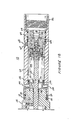
- FIGs 1A and 1B illustrate a fluid pressure actuated firing head for oil and/or gas well perforating guns, embodying one particularly advantageous application of the present invention.
- a generally cylindrical disarm sub 12 is provided with a pin type coupling 14 at a first end of the firing head 10 and adapted to form a threaded coupling with another downhole tool or with a joint of tubing in a tubing string.
- An opposed end of the disarm sub 12 forms a threaded connection with a tubular member 15 at a first end thereof.
- An O-ring 18 provides a fluid-tight seal between the outer surface of sub 12 and the inner surface of tubular member 15.
- An opposed, second end of the tubular member 15 is threadedly coupled to a piston chamber sub 22 at a first end thereof.
- An O-ring 24 seals the outer surface of sub 22 to the inner surface of tubular member 15, while a further pair of set screws 26 prevent decoupling of tubular member 15 and sub 22.
- An intermediate sub 23 is threadedly coupled to sub 22 at a second end thereof.
- An O-ring 25 seals the outer surface of r.ub 22 to the inner surface of intermediate sub 23, while a pair of set screws 27 prevent decoupling of sub 22 and sub 23.
- an opposed, second end of sub 23 is threadedly coupled to a tubular housing 28 and an 0-ring 30 seals the exterior surface of the sub 23 to the interior surface of the housing 28, while two additional set screws 32 prevent decoupling of the sub 22 from the housing 28.
- An opposed, second end of the housing 28 is provided with a box type coupling 36 adapted to from a fluid-tight connection with the housing of a perforating gun.
- a disarm piston 40 is slidably positioned within the disarm sub 12 initially adjacent the first or pin end 14 thereof and forming a fluid-tight seal against the inner surface of the sub 12 by means of an O-ring seal 42.
- Four transverse ports 44 are formed through the piston 40 and are initially aligned with corresponding ports 46 formed through the sides of the disarm sub 12.
- Disarm piston 40 is also provided with an axial center bore 48 extending therethrough and in communication with the ports 44 thereof, so that the exterior of the disarm sub 12 and of the firing head 10 is in fluid pressure communication with the interior of the disarm sub 12 and, initially, with the interior of the tool or tubing joint coupled to the firing head 10 at the pin end 14.
- a plurality of shear pins 50 maintain the initial position of the disarm piston 40 axially with respect to the disarm sub 12.
- Disarm plug 54 having a lower, generally cylindrically shaped portion 56 adapted to seat in the port 48 of the disarm piston 40 and to form a fluid-tight seal thereagainst by virtue of a chevron-type seal 58 provided in the lower portion 56.
- Disarm plug 54 is also provided with a fishing neck 60 which permits the plug 54 to be retrieved, if so desired.
- a disarm sleeve 64 is slidably mounted on the exterior of the tubular member 15 and the disarm sub 12.
- the disarm sub 12 is provided with four axially extending slots 66 (only two of which are shown in Figure 1A) extending therethrough adjacent a first end of the disarm sleeve 64.
- screws 70 are threaded into and retained by the disarm piston 40 and extend radially outwardly therefrom through the slots 66 and into four circular bores formed in the disarm sleeve 64 adjacent its first end, such that a sliding movement of the piston 40 inwardly of the disarm sub 12 from the pin end 14 will cause the sleeve 64 to slide over the disarm sub 12 and the tubular member 15 to the extent that the slots 66 permit the screws 70 to travel axially therethrough.
- a shoulder 72 is formed in the intermediate sub 23 thus to prevent further axial movement of the sleeve 64 which might shear the screws 70 with a consequent loss of control over the position of the sleeve 64.
- a detonation initiator 80 is received within a central bore of a retaining member 82 positioned within the housing 28 adjacent the box coupling 36 thereof, such that a threaded end of a perforating gun coupled thereto abuts a first extremity of the detonation initiator 80 .and the retaining member 82, thus opposing movement thereof outwardly of the housing 28.
- Two O-ring seals 84 seal an outer cylindrical surface of the retaining member 82 against an inner surface of the housing 28.
- the detonation initiator 80 is an impact type detonator adapted to provide a detonating output to the perforating guns when struck at an opposite extremity by a firing pin 86.
- a plurality of 0-rings 90 seal the exterior of the detonation initiator 80 to the interior of the retaining member 82.
- the detonation initiator 80 may utilize, for example, a percussion primer of the type disclosed in United States patent application serial No. 587,344 entitled PRIMER MIX, PERCUSSION PRIMER AND METHOD OF INITIATING COMBUSTION filed March 8, 1984 in the name of Donald N. Yates and assigned to the assignee of the present application, the entire disclosure of which is incorporated herein by reference.
- An exemplary primer mix includes 41% by weight titanium and 59% by weight potassium perchlorate compacted to a density of from 2.3 to 2.5 gm/cc by subjection to compaction pressure of from 15,000 to 50,000 psi (103 to 345 MPa).
- the firing pin 86 is carried by a plunger 94 positioned slidably within a central bore of a plunger housing 96 abutting the retaining member 82.
- the exterior surface of the plunger 94 is sealed against the central bore of the housing 96 by a pair of 0-ring seals 98.
- the plunger housing 96 is held between the retaining member 82 (at a first end of the housing 96) and a shoulder 100 of the housing 28, such that it is immovable with respect to the housing 28.
- An annularly shaped shock absorber 101 is retained between member 82 and housing 96 and serves to prevent damage to the plunger 94 upon firing.
- An outer surface of the housing 96 is sealed against an inner surface of the housing 28 by two 0-ring seals 102.
- the plunger housing 96 has a reduced diameter neck portion 106 adjacent a second end thereof and having four circular bores radially therethrough (of which only two are shown in Figure 1B) in which four steel balls 108 are captured between an annular indentation in the plunger 94 having a generally semi-circular configuration to conform with the shape of the balls 108, and a cup-shaped ball release 110 positioned over the neck portion 106 of the plunger housing 96 and releasably affixed thereto by a plurality of shear pins 112.
- the shear pins 112 are maintained within the ball release 110 by a generally cylindrical pin retainer 114 threadedly coupled over the ball release 110 and restraining the pins 112 from slipping outwardly of the neck 106 and ball release 110.
- the ball release 110 is threadedly coupled to a rod 120 at a first end thereof.
- the rod 120 extends from the ball release 110 toward the pin end 14 axially through the housing 28, the intermediate sub 23 and the piston chamber sub 22 ( Figure 1A).
- a first piston 122 is threadedly coupled with the rod 120 at an opposed end thereof and is positioned within a central bore of piston chamber sub 22.
- the piston 122 forms a fluid-tight seal with the central bore of sub 22 by virtue of two O-rings 130.
- Piston 122 has a first, relatively large diameter recess 123 extending from a first end 124 thereof towards the box end 36 of the firing head 10 and terminating at an inwardly extending shoulder 125 of piston 122.
- a second, relatively smaller diameter recess 126 within piston 122 extends from shoulder 125 towards the box end 36 of firing head 10. Second recess 126 terminates at an inner wall 127 of piston 122.
- a plurality of fluid passageways 128 extend from the inner wall 127 of piston 122 through an outer wall 129 thereof closest the box end 36.
- a second piston 132 has a first, relatively small diameter portion 133 extending partially into recess 126 of piston 122 and having an outer wall fitting closely with recess 126 of piston 122.
- the outer surface of portion 133 is sealed against recess 126 by an O-ring 134.
- Portion 133 extends from recess 126 towards the pin end 14 of firing head 10 and terminates at a second, relatively larger diameter portion 135 of piston 132 having an outer surface fitting closely against the recess 123 of piston 122.
- the second portion 135 of piston 132 is sealed against the recess 123 of piston 122 by an O-ring 136.
- An annular air chamber 137 is defined between the outer surface of portion 133 and the wall of.the recess 123 of piston 122.
- a shear pin ring 138 abuts the shoulder 125 of piston 122 and is releasably secured to piston 132 by a plurality of shear pins 139. Accordingly, the shear pins 139 and the shear pin ring 138 releasably secure the piston 132 against movement inwardly of piston 122 until sufficient force is exerted against the pins 139 to shear them.
- a disc shaped piston stop 140 abuts wall 127 of piston 122 and is provided with a plurality of fluid passageways therethrough to ensure fluid communication between the interior of recess 126 and the passageways 128. The piston stop 140 serves to absorb the shock of impact between the portion 133 of piston 132 and the wall 127 of piston 122, as will be described in greater detail below.
- a radial port 141 extends through the larger diameter portion 135 of piston 132 and is in fluid communication with the volume 177 bounded by the interior of the tubular member 15.
- a longitudinal port 142 in fluid communication with the port 141 extends through the relatively smaller diameter portion 133 of piston 132 and is in fluid communication with the volume defined between the portion 133, the recess 126 of piston 122 and the stop 140. Accordingly, while the piston 132 is maintained in the position shown in Figure 1A, there is fluid communication between the volume 177 and the exterior of the piston 122, on the one hand, and the fluid volume adjacent the side 129 of the piston 122.
- This volume is filled with a clean fluid such as oil or diesel fuel, so that the narrow passages exten&ing through the stop 140 and the passages 128 in piston 122 do not become clogged with particulate matter present in well fluids on the exterior of firing head 10.
- Two O-rings 146 are positioned within annular recesses in the exterior of portion 135 of piston 132 and positioned to seal the port 141 from the volume 177 within the tubular member 15 when the piston 132 has been fully extended into the piston 122.
- An axial extremity of the volume within tubular member 15 and closest to the pin end 14 is defined by a floating piston 170 slidably disposed within the member 15 and sealed thereto by two 0-ring seals 172.
- the opposite side of the floating piston 170 is exposed to well fluids admitted through the ports 46 in the disarm sub 12 and the ports 44 in the piston 40, and is also in communication with the interior of the tubing or other tool coupled at the pin end 14 through the port 48 in the piston 40.
- a plurality of ports 173 extending through piston 170 are closed by a frangible shim 174 held within piston 170.
- the use of shim 174 prevents the build up of a pressure differential between the volume 177 within tubular member 15 and piston 170, and the exterior of the firing head 10.
- the volume on the side of piston 170 opposite volume 177 and within the disarm sub 12 is designated 175.
- An additional floating piston 176 is provided on the opposite side of the first piston 122 and forms a slidable seal against a relatively large diameter, inner surface of the intermediate sub 23 by virtue of two O-ring seals 178 and forms a slidable seal against the rod 120 by virtue of two additional O-ring seals 180.
- the interior surface of the sub 23 and the piston 176 enclose a chamber 181 filled with nitrogen through a check valve 182 ( Figure 1 B ) providing fluid communication from the exterior of the sub 23 to the nitrogen chamber 181.
- An extremity of the intermediate sub 23 opposite the piston 122 has a reduced diameter axial bore which forms a fluid-tight seal against the rod 120 by virtue of two further 0-rings seals 186 ( Figure 1B).
- Adjacent this extremity of intermediate sub 23 are formed four radial ports 190 (only two of which are shown in Figure 1B) through the housing 28 admitting fluid pressure on the exterior of firing head 10 therethrough into the chamber defined between the seals 186 and an additional floating piston 192 sealed at its outer surface against the interior surface of the housing 128 by additional O-ring seals 194 and sealed against the rod 120 by still further O-ring seals 196 between the floating piston 192 and the rod 120.
- the volume 200 between the interior wall of the housing 28, the rod 120, the piston 192 and the retaining member 96 is filled with a clean fluid, such as oil or diesel fuel.
- Piston 192 has a plurality of ports therethrough closed by a shim 193 held within piston 192.
- shim 193 prevents build up of a pressure differential between the volume 200 and the exterior of the firing head 10.
- a rupture disc retainer 201 having a port therethrough closed by a rupturable disc 202 is threadedly received in the outer wall of housing 28, so that the disc 202 is exposed to pressure in the volume 200 on its interior side and exposed to borehole pressure on its exterior side.
- Disc 202 is selected so that it spontaneously ruptures when the pressure differential across it exceeds 500 psi (3.5 MPa). Accordingly, a means is provided for releasing pressure which might be trapped in volume 200 when the firing head 10 is retrieved from the borehole.
- Figure 2 illustrates a portion of a borehole formed in the earth and lined with a casing 210.
- a tubing string 214 is coupled at its lower end to the pin end 14 of disarm sub 12 of the firing head 10.
- the box end 36 of the firing head 10 is threadedly coupled to a string of perforating guns 218 extending downwardly therefrom and positioned opposite a portion 220 of the casing 210 which it is desired to perforate with the guns 218.
- a shot detection device 222 which is operative to provide a signal transmitted upwardly through the tubing string 214 to the wellhead after a time delay provided by a combustive time delay element incorporated within the shot detection device 222.
- Shot detection device 222 may be, for example, that disclosed in U.S. Patent Application Serial No. 505,911 filed June 20, 1983 in the names of Edward A. Colle, Jr., et al. entitled METHOD AND APPARATUS FOR DETECTING FIRING OF PERFORATING GUN.
- a packer 226 carried by the tubing string 214 and positioned above the firing head 10 is set to isolate the casing annulus therebelow from the annulus above the packer.
- the firing head 10 is actuated to fire the perforating guns 218 through a two-step procedure, wherein (1) tubing pressure which is applied through the port 48 of disarm piston 12 is increased above a first predetermined value in excess of hydrostatic pressure, thus to arm the firing head 10, and (2) the firing head is thereafter fired by reducing the tubing pressure to a second pressure level.
- tubing pressure is applied through the port 48 through pin end 14, as indicated above.
- the pressure in volume 175 is thus increased accordingly.
- This pressure is applied substantially undiminished through the floating piston 170 to the volume of clear fluid 177 on its opposite side. Since at this time a fluid pressure path exists from the volume 177 through the ports 141, 142 and 128 to the floating piston 176, the nitrogen gas previously stored in volume 181 is in equilibrium with the pressure in volumes 177 and 175 through the floating piston 176.
- the firing head 10 may be arranged for arming and firing through a wide range of fluid pressure values, determined from time to time simply through the proper selection of the shear pins 112 and 139. Accordingly, it is possible to provide a firing head, or other explosion initiator, which is to be fired either at, above or below hydrostatic pressure.
- the firing head of the instant embodiment is particularly useful where it is desired to perforate the casing of a borehole with an underbalanced condition and requiring only the adjustment of tubing pressure to carry out the firing sequence.
- the guns 218 and firing head 10 are run into the well on tubing 214 and, prior to setting the packer 226, a light fluid is pumped down the tubing to circulate drilling mud out of the tubing string 214 through the ports 46 of disarm sub 12. If a sufficient underbalance is thereby achieved, the packer 226 is then set. If it is desired to reduce the pressure opposite the interval 220 at the time of perforation to an even lower value, the fluid in the tubing 214 can be circulated out by pumping nitrogen down the tubing and then setting the packer 226, or by setting the packer and then swabbing out a desired amount of fluid from the tubing 214.
- pump pressure may be increased so that the pressure applied through the port 48 of the firing head 10 is increased sufficiently to arm the firing head.
- nitrogen may be pumped down on top of a partial column of fluid to achieve the necessary arming pressure. Thereafter, either pump pressure is reduced or nitrogen is bled off until the predetermined firing pressure is achieved, whereupon the guns 218 are fired by the firing head 10.
- the disarm sequence for the particular embodiment of Figures 1A and 1B involves first, dropping the disarm plug 54 ( Figure 1A) downwardly through the tubing to seat in the port 48 of the disarm piston 40.
- the chevron seals 58 in the disarm plug 54 form a fluid-tight seal against the walls of the port 48, so that tubing pressure may be increased to produce a pressure differential across the disarm piston 40.
- Eight ports 230 are provided through the disarm sleeve 64 and four additional ports 232 are provided through the intermediate sub 23 communicating the exterior thereof with the fluid volume on the side of piston 122 opposite the pin end 14. So long as the disarm sleeve 64 is in the position shown in Figure 1A, the ports 232 are sealed against fluid communication with exterior of the firing head 10 by virtue of two 0-ring seals 234 provided on opposite sides of the ports 232 and sealing the outer surface of the sub 23 against the interior of the disarm sleeve 64.
- the ports 230 in the sleeve 64 are aligned with the ports 232 through the sub 23, so that the fluid volume on the side of the piston 122 opposite the pin end 14 is thereby brought into fluid pressure communication with the exterior of the firing head 10.
- the fluid pressure in the volume 175 is maintained in communication with the pressure on the exterior of the firing head 10 through the ports 44 in the piston 40 and the slots 66 in the disarm sub 12.
- the equalizing piston 170 maintains the pressure in the volume 177 equal to that in the volume 175.
- the pressure across the piston 122 is thereby equalized, so that if the firing head has not yet fired, it is then disabled from firing.
- the seal 42 on piston 40 slides past ports 46. This communicates the exterior of the firing head 10 with the interior of the tubing. Accordingly, when this happens, a drop in tubing pressure occurs which is detectable at the surface. It is thus possible to determine positively that the firing head 10 has been disarmed. This is particularly advantageous in operations, such as drill stem testing, where it is the normal practice to retrieve the tool string from the well when the operation is completed, since the perforating guns may be brought to the surface with the foreknowledge that the firing head is disarmed.
- the invention also includes in addition to or separate from the invention claimed, the following features:
Landscapes
- Geology (AREA)
- Life Sciences & Earth Sciences (AREA)
- Engineering & Computer Science (AREA)
- Mining & Mineral Resources (AREA)
- Environmental & Geological Engineering (AREA)
- Fluid Mechanics (AREA)
- Physics & Mathematics (AREA)
- General Life Sciences & Earth Sciences (AREA)
- Geochemistry & Mineralogy (AREA)
- Earth Drilling (AREA)
- Nozzles (AREA)
- Finger-Pressure Massage (AREA)
- Actuator (AREA)
Abstract

Description
- The present invention relates to devices for use in boreholes such as oil and/or gas wells.
- Explosive devices downhole in a well are typically actuated by steps taken at the surface of the well. Such steps include, for example, dropping a detonating bar downhole to impact a firing head, transmitting an electrical signal downhole to a wireline operated explosive, applying pressure from the surface to actuate an explosive device and manipulating a tubing string or tool string from the surface to do so. It will be readily appreciated that since such actions are taken at a location separated from the explosives by a borehole filled with fluid, it is not absolutely certain that the explosive device has been actuated, although the appropriate steps have been taken.
- Accordingly, when the explosive device is retrieved from the borehole, it is desirable to take steps to ensure it has been disarmed before it arrives at the surface.
- In accordance with one aspect of the present invention, an apparatus is provided for actuating an explosive device downhole in a borehole. The apparatus comprises means for actuating the explosive device in response to a stimulus, and means for disarming the actuating means in response to the application of fluid pressure thereto.
- In accordance with another aspect of the present invention, a method of disarming a perforating gun downhole in a borehole is provided wherein the perforating gun has a pressure responsive disarming device. The method comprises the steps of: applying increased fluid pressure to the disarming device in excess of a predetermined level, and actuating the disarming device in response to the increased fluid pressure.
- In order that the invention may be more fully understood, an embodiment thereof will now be described by way of example only, with reference to the accompanying drawings, wherein:
- FIGURES 1A and 1B are partially cross-sectional views of a pressure actuated perforating gun firing head, and disarm plug, in accordance with one advantageous embodiment of the present invention;
- FIGURE 2 is a partially cross-sectional view of a borehole in the earth wherein tubing conveyed perforating guns
- Figures 1A and 1B illustrate a fluid pressure actuated firing head for oil and/or gas well perforating guns, embodying one particularly advantageous application of the present invention. With reference particularly to Figure 1A, a generally
cylindrical disarm sub 12 is provided with apin type coupling 14 at a first end of thefiring head 10 and adapted to form a threaded coupling with another downhole tool or with a joint of tubing in a tubing string. An opposed end of thedisarm sub 12 forms a threaded connection with atubular member 15 at a first end thereof. An O-ring 18 provides a fluid-tight seal between the outer surface ofsub 12 and the inner surface oftubular member 15. Two set screws 20-oppose decoupling of thesub 12 from thetubular member 15. - An opposed, second end of the
tubular member 15 is threadedly coupled to a piston chamber sub 22 at a first end thereof. An O-ring 24 seals the outer surface of sub 22 to the inner surface oftubular member 15, while a further pair of setscrews 26 prevent decoupling oftubular member 15 and sub 22. Anintermediate sub 23 is threadedly coupled to sub 22 at a second end thereof. An O-ring 25 seals the outer surface of r.ub 22 to the inner surface ofintermediate sub 23, while a pair ofset screws 27 prevent decoupling of sub 22 andsub 23. With reference to Figure 1B, an opposed, second end ofsub 23 is threadedly coupled to atubular housing 28 and an 0-ring 30 seals the exterior surface of thesub 23 to the interior surface of thehousing 28, while twoadditional set screws 32 prevent decoupling of the sub 22 from thehousing 28. An opposed, second end of thehousing 28 is provided with abox type coupling 36 adapted to from a fluid-tight connection with the housing of a perforating gun. - With reference again to Figure 1A, a
disarm piston 40 is slidably positioned within thedisarm sub 12 initially adjacent the first orpin end 14 thereof and forming a fluid-tight seal against the inner surface of thesub 12 by means of an O-ring seal 42. Fourtransverse ports 44 are formed through thepiston 40 and are initially aligned withcorresponding ports 46 formed through the sides of thedisarm sub 12.Disarm piston 40 is also provided with anaxial center bore 48 extending therethrough and in communication with theports 44 thereof, so that the exterior of thedisarm sub 12 and of thefiring head 10 is in fluid pressure communication with the interior of thedisarm sub 12 and, initially, with the interior of the tool or tubing joint coupled to thefiring head 10 at thepin end 14. A plurality of shear pins 50 maintain the initial position of thedisarm piston 40 axially with respect to thedisarm sub 12. - Also shown in Figure 1A is a
disarm plug 54 having a lower, generally cylindrically shaped portion 56 adapted to seat in theport 48 of thedisarm piston 40 and to form a fluid-tight seal thereagainst by virtue of a chevron-type seal 58 provided in the lower portion 56.Disarm plug 54 is also provided with afishing neck 60 which permits theplug 54 to be retrieved, if so desired. - A
disarm sleeve 64 is slidably mounted on the exterior of thetubular member 15 and thedisarm sub 12. Thedisarm sub 12 is provided with four axially extending slots 66 (only two of which are shown in Figure 1A) extending therethrough adjacent a first end of thedisarm sleeve 64. Four screws 70 (only two of which are shown in Figure 1A) are threaded into and retained by thedisarm piston 40 and extend radially outwardly therefrom through theslots 66 and into four circular bores formed in thedisarm sleeve 64 adjacent its first end, such that a sliding movement of thepiston 40 inwardly of thedisarm sub 12 from thepin end 14 will cause thesleeve 64 to slide over thedisarm sub 12 and thetubular member 15 to the extent that theslots 66 permit the screws 70 to travel axially therethrough. Ashoulder 72 is formed in theintermediate sub 23 thus to prevent further axial movement of thesleeve 64 which might shear the screws 70 with a consequent loss of control over the position of thesleeve 64. - With reference to Figure 1B, a detonation initiator 80 is received within a central bore of a retaining member 82 positioned within the
housing 28 adjacent thebox coupling 36 thereof, such that a threaded end of a perforating gun coupled thereto abuts a first extremity of the detonation initiator 80 .and the retaining member 82, thus opposing movement thereof outwardly of thehousing 28. Two O-ring seals 84 seal an outer cylindrical surface of the retaining member 82 against an inner surface of thehousing 28. - The detonation initiator 80 is an impact type detonator adapted to provide a detonating output to the perforating guns when struck at an opposite extremity by a firing pin 86. A plurality of 0-rings 90 seal the exterior of the detonation initiator 80 to the interior of the retaining member 82. The detonation initiator 80 may utilize, for example, a percussion primer of the type disclosed in United States patent application serial No. 587,344 entitled PRIMER MIX, PERCUSSION PRIMER AND METHOD OF INITIATING COMBUSTION filed March 8, 1984 in the name of Donald N. Yates and assigned to the assignee of the present application, the entire disclosure of which is incorporated herein by reference. An exemplary primer mix includes 41% by weight titanium and 59% by weight potassium perchlorate compacted to a density of from 2.3 to 2.5 gm/cc by subjection to compaction pressure of from 15,000 to 50,000 psi (103 to 345 MPa).
- The firing pin 86 is carried by a plunger 94 positioned slidably within a central bore of a plunger housing 96 abutting the retaining member 82. The exterior surface of the plunger 94 is sealed against the central bore of the housing 96 by a pair of 0-ring seals 98. The plunger housing 96 is held between the retaining member 82 (at a first end of the housing 96) and a
shoulder 100 of thehousing 28, such that it is immovable with respect to thehousing 28. An annularly shaped shock absorber 101 is retained between member 82 and housing 96 and serves to prevent damage to the plunger 94 upon firing. An outer surface of the housing 96 is sealed against an inner surface of thehousing 28 by two 0-ring seals 102. The plunger housing 96 has a reduceddiameter neck portion 106 adjacent a second end thereof and having four circular bores radially therethrough (of which only two are shown in Figure 1B) in which four steel balls 108 are captured between an annular indentation in the plunger 94 having a generally semi-circular configuration to conform with the shape of the balls 108, and a cup-shaped ball release 110 positioned over theneck portion 106 of the plunger housing 96 and releasably affixed thereto by a plurality of shear pins 112. The shear pins 112 are maintained within theball release 110 by a generallycylindrical pin retainer 114 threadedly coupled over theball release 110 and restraining the pins 112 from slipping outwardly of theneck 106 andball release 110. - The
ball release 110 is threadedly coupled to arod 120 at a first end thereof. Therod 120 extends from theball release 110 toward thepin end 14 axially through thehousing 28, theintermediate sub 23 and the piston chamber sub 22 (Figure 1A). A first piston 122 is threadedly coupled with therod 120 at an opposed end thereof and is positioned within a central bore of piston chamber sub 22. The piston 122 forms a fluid-tight seal with the central bore of sub 22 by virtue of two O-rings 130. - Piston 122 has a first, relatively large diameter recess 123 extending from a
first end 124 thereof towards thebox end 36 of thefiring head 10 and terminating at an inwardly extendingshoulder 125 of piston 122. A second, relatively smaller diameter recess 126 within piston 122 extends fromshoulder 125 towards thebox end 36 offiring head 10. Second recess 126 terminates at an inner wall 127 of piston 122. A plurality of fluid passageways 128 extend from the inner wall 127 of piston 122 through an outer wall 129 thereof closest thebox end 36. - A second piston 132 has a first, relatively small diameter portion 133 extending partially into recess 126 of piston 122 and having an outer wall fitting closely with recess 126 of piston 122. The outer surface of portion 133 is sealed against recess 126 by an O-ring 134. Portion 133 extends from recess 126 towards the
pin end 14 offiring head 10 and terminates at a second, relativelylarger diameter portion 135 of piston 132 having an outer surface fitting closely against the recess 123 of piston 122. Thesecond portion 135 of piston 132 is sealed against the recess 123 of piston 122 by an O-ring 136. An annular air chamber 137 is defined between the outer surface of portion 133 and the wall of.the recess 123 of piston 122. - A shear pin ring 138 abuts the
shoulder 125 of piston 122 and is releasably secured to piston 132 by a plurality ofshear pins 139. Accordingly, theshear pins 139 and the shear pin ring 138 releasably secure the piston 132 against movement inwardly of piston 122 until sufficient force is exerted against thepins 139 to shear them. A disc shaped piston stop 140 abuts wall 127 of piston 122 and is provided with a plurality of fluid passageways therethrough to ensure fluid communication between the interior of recess 126 and the passageways 128. The piston stop 140 serves to absorb the shock of impact between the portion 133 of piston 132 and the wall 127 of piston 122, as will be described in greater detail below. - A
radial port 141 extends through thelarger diameter portion 135 of piston 132 and is in fluid communication with thevolume 177 bounded by the interior of thetubular member 15. A longitudinal port 142 in fluid communication with theport 141 extends through the relatively smaller diameter portion 133 of piston 132 and is in fluid communication with the volume defined between the portion 133, the recess 126 of piston 122 and the stop 140. Accordingly, while the piston 132 is maintained in the position shown in Figure 1A, there is fluid communication between thevolume 177 and the exterior of the piston 122, on the one hand, and the fluid volume adjacent the side 129 of the piston 122. This volume is filled with a clean fluid such as oil or diesel fuel, so that the narrow passages exten&ing through the stop 140 and the passages 128 in piston 122 do not become clogged with particulate matter present in well fluids on the exterior of firinghead 10. Two O-rings 146 are positioned within annular recesses in the exterior ofportion 135 of piston 132 and positioned to seal theport 141 from thevolume 177 within thetubular member 15 when the piston 132 has been fully extended into the piston 122. - An axial extremity of the volume within
tubular member 15 and closest to thepin end 14 is defined by a floating piston 170 slidably disposed within themember 15 and sealed thereto by two 0-ring seals 172. The opposite side of the floating piston 170 is exposed to well fluids admitted through theports 46 in the disarmsub 12 and theports 44 in thepiston 40, and is also in communication with the interior of the tubing or other tool coupled at thepin end 14 through theport 48 in thepiston 40. A plurality ofports 173 extending through piston 170 are closed by a frangible shim 174 held within piston 170. The use of shim 174 prevents the build up of a pressure differential between thevolume 177 withintubular member 15 and piston 170, and the exterior of the firinghead 10. The volume on the side of piston 170opposite volume 177 and within the disarmsub 12 is designated 175. - An additional floating
piston 176 is provided on the opposite side of the first piston 122 and forms a slidable seal against a relatively large diameter, inner surface of theintermediate sub 23 by virtue of two O-ring seals 178 and forms a slidable seal against therod 120 by virtue of two additional O-ring seals 180. The interior surface of thesub 23 and thepiston 176 enclose achamber 181 filled with nitrogen through a check valve 182 (Figure 1B) providing fluid communication from the exterior of thesub 23 to thenitrogen chamber 181. An extremity of theintermediate sub 23 opposite the piston 122 has a reduced diameter axial bore which forms a fluid-tight seal against therod 120 by virtue of two further 0-rings seals 186 (Figure 1B). - Adjacent this extremity of
intermediate sub 23 are formed four radial ports 190 (only two of which are shown in Figure 1B) through thehousing 28 admitting fluid pressure on the exterior of firinghead 10 therethrough into the chamber defined between theseals 186 and an additional floating piston 192 sealed at its outer surface against the interior surface of the housing 128 by additional O-ring seals 194 and sealed against therod 120 by still further O-ring seals 196 between the floating piston 192 and therod 120. Thevolume 200 between the interior wall of thehousing 28, therod 120, the piston 192 and the retaining member 96 is filled with a clean fluid, such as oil or diesel fuel. Piston 192 has a plurality of ports therethrough closed by ashim 193 held within piston 192. Like shim 174 of piston 170,shim 193 prevents build up of a pressure differential between thevolume 200 and the exterior of the firinghead 10. Arupture disc retainer 201 having a port therethrough closed by arupturable disc 202 is threadedly received in the outer wall ofhousing 28, so that thedisc 202 is exposed to pressure in thevolume 200 on its interior side and exposed to borehole pressure on its exterior side.Disc 202 is selected so that it spontaneously ruptures when the pressure differential across it exceeds 500 psi (3.5 MPa). Accordingly, a means is provided for releasing pressure which might be trapped involume 200 when the firinghead 10 is retrieved from the borehole. - One possible downhole arrangement utilizing the firing head of Figures of 1A and 1B is shown in Figure 2 which illustrates a portion of a borehole formed in the earth and lined with a
casing 210. Atubing string 214 is coupled at its lower end to thepin end 14 of disarmsub 12 of the firinghead 10. Thebox end 36 of the firinghead 10 is threadedly coupled to a string of perforatingguns 218 extending downwardly therefrom and positioned opposite aportion 220 of thecasing 210 which it is desired to perforate with theguns 218. Coupled to the guns at their lowermost extremity is ashot detection device 222 which is operative to provide a signal transmitted upwardly through thetubing string 214 to the wellhead after a time delay provided by a combustive time delay element incorporated within theshot detection device 222.Shot detection device 222 may be, for example, that disclosed in U.S. Patent Application Serial No. 505,911 filed June 20, 1983 in the names of Edward A. Colle, Jr., et al. entitled METHOD AND APPARATUS FOR DETECTING FIRING OF PERFORATING GUN. - Once the
guns 218 have been positioned adjacent the desiredlocation 220, apacker 226 carried by thetubing string 214 and positioned above the firinghead 10 is set to isolate the casing annulus therebelow from the annulus above the packer. In the particular arrangement of Figure 2, the firinghead 10 is actuated to fire the perforatingguns 218 through a two-step procedure, wherein (1) tubing pressure which is applied through theport 48 of disarmpiston 12 is increased above a first predetermined value in excess of hydrostatic pressure, thus to arm the firinghead 10, and (2) the firing head is thereafter fired by reducing the tubing pressure to a second pressure level. With reference to Figures 1A and 1B, tubing pressure is applied through theport 48 throughpin end 14, as indicated above. The pressure involume 175 is thus increased accordingly.. This pressure is applied substantially undiminished through the floating piston 170 to the volume ofclear fluid 177 on its opposite side. Since at this time a fluid pressure path exists from thevolume 177 through theports 141, 142 and 128 to the floatingpiston 176, the nitrogen gas previously stored involume 181 is in equilibrium with the pressure involumes piston 176. - As the pressure in the
volume 177 is thus increased, the force across the piston 132 produced by fluid pressure against the extremity thereofadjacent volume 177 and the surface thereof defining the first extremity of the air chamber between the portion 133 of the piston 132 and the recess 123 correspondingly increases, until thepins 139 fail and the piston 132 slides within piston 122, abutting the piston stop 140. O-rings 146 thus form a fluid-tight seal betweenportion 135 of piston 132 and recess 123 of piston 122, sealing offport 141 fromvolume 177. It will be seen that fluid pressure within thenitrogen chamber 181, as well as fluid pressure exerted against wall 129 of the piston 122 opposite thepin end 14 of firinghead 10 is thus trapped. It will be appreciated that it is not necessary to know the hydrostatic pressure precisely when applying tubing pressure in this manner to arm the firinghead 10, since it is only necessary to increase tubing pressure sufficiently so that it is reasonably certain that theshear pirts 139 have broken. It will also be seen that if, for any reason the firing head does not arm in this manner, the procedure may be repeated with relative ease and expeditiously. The force of the piston 84 132 striking the wall 127 is largely absorbed by the piston stop 140. This helps prevent damage to the apparatus, and also helps prevent premature firing of the firinghead 10 by minimizing the shock experienced by shear pins 112 when piston 132 impacts the stop 140. - With reference again to Figure 1B, it is seen that lower annulus pressure is communicated within the
housing 28 through theports 190 and thus is applied through the floating piston 192 to the clean fluid in thevolume 200. The fluid pressure in thevolume 200 is applied to the surface of the plunger 94 opposite the firing pin 86, which is restrained against striking the detonation initiator 80 so long as the balls 108 are retained within theneck 106 of the housing 96. As the tubing pressure is reduced subsequent to the increase which armed the firing head as described above, the force across the piston 122 produced by the pressure against its wall 129 opposite thepin end 14 and the reduced pressure on the opposing side of the piston 122 is coupled through therod 120 to therelease member 110. When this force becomes sufficiently great, the shear pins 112 fail so that the piston 122 is driven towards thepin end 14, thus pulling theball release 110 off theneck 106 and freeing the balls 108 holding the plunger 94. The firing pin 86 is then driven into the initiator 80 by hydrostatic pressure applied to the opposite side of plunger 94, so that initiator 80 yields a detonating output at its opposed end to fire theguns 218. - It will be appreciated that the firing
head 10 may be arranged for arming and firing through a wide range of fluid pressure values, determined from time to time simply through the proper selection of the shear pins 112 and 139. Accordingly, it is possible to provide a firing head, or other explosion initiator, which is to be fired either at, above or below hydrostatic pressure. The firing head of the instant embodiment is particularly useful where it is desired to perforate the casing of a borehole with an underbalanced condition and requiring only the adjustment of tubing pressure to carry out the firing sequence. - In one exemplary method, the
guns 218 and firinghead 10 are run into the well ontubing 214 and, prior to setting thepacker 226, a light fluid is pumped down the tubing to circulate drilling mud out of thetubing string 214 through theports 46 of disarmsub 12. If a sufficient underbalance is thereby achieved, thepacker 226 is then set. If it is desired to reduce the pressure opposite theinterval 220 at the time of perforation to an even lower value, the fluid in thetubing 214 can be circulated out by pumping nitrogen down the tubing and then setting thepacker 226, or by setting the packer and then swabbing out a desired amount of fluid from thetubing 214. If there is then a full column of light fluid in thetubing 214, pump pressure may be increased so that the pressure applied through theport 48 of the firinghead 10 is increased sufficiently to arm the firing head. If there is not a full column of fluid in thetubing 214, nitrogen may be pumped down on top of a partial column of fluid to achieve the necessary arming pressure. Thereafter, either pump pressure is reduced or nitrogen is bled off until the predetermined firing pressure is achieved, whereupon theguns 218 are fired by the firinghead 10. - When it is desired to disarm the firing
head 10, this can be achieved principally through the provision of disarming means responsive to an increase in the pressure applied across the disarmpiston 40, for example, applied through the tubing, causing thepiston 40 to shift and effectively prevent subsequent actuation of the firing head. With reference to Figure 1A, the disarm sequence for the particular embodiment of Figures 1A and 1B involves first, dropping the disarm plug 54 (Figure 1A) downwardly through the tubing to seat in theport 48 of the disarmpiston 40. The chevron seals 58 in the disarm plug 54 form a fluid-tight seal against the walls of theport 48, so that tubing pressure may be increased to produce a pressure differential across the disarmpiston 40. When this pressure differential exceeds a predetermined amount, the shear pins 50 holding the disarm piston immovable with respect to the disarmsub 12, fail so that thepiston 40 shifts inwardly of thepin end 14. Since the disarmsleeve 64 is coupled to the piston through the screws 70, the disarm sleeve likewise shifts downwardly away from thepin end 14. - Eight ports 230 (of which only two are shown in Figure 1A) are provided through the disarm
sleeve 64 and fouradditional ports 232 are provided through theintermediate sub 23 communicating the exterior thereof with the fluid volume on the side of piston 122 opposite thepin end 14. So long as the disarmsleeve 64 is in the position shown in Figure 1A, theports 232 are sealed against fluid communication with exterior of the firinghead 10 by virtue of two 0-ring seals 234 provided on opposite sides of theports 232 and sealing the outer surface of thesub 23 against the interior of thedisarm sleeve 64. When, however, the disarmsleeve 64 has been shifted away from thepin end 14 through the motion of thepiston 40, theports 230 in thesleeve 64 are aligned with theports 232 through thesub 23, so that the fluid volume on the side of the piston 122 opposite thepin end 14 is thereby brought into fluid pressure communication with the exterior of the firinghead 10. At the same time, the fluid pressure in thevolume 175 is maintained in communication with the pressure on the exterior of the firinghead 10 through theports 44 in thepiston 40 and theslots 66 in the disarmsub 12. As noted above, the equalizing piston 170 maintains the pressure in thevolume 177 equal to that in thevolume 175. Accordingly, the pressure across the piston 122 is thereby equalized, so that if the firing head has not yet fired, it is then disabled from firing. When thepiston 40 shifts due to the application of pressure to disarm the firing head, the seal 42 onpiston 40 slides pastports 46. This communicates the exterior of the firinghead 10 with the interior of the tubing. Accordingly, when this happens, a drop in tubing pressure occurs which is detectable at the surface. It is thus possible to determine positively that the firinghead 10 has been disarmed. This is particularly advantageous in operations, such as drill stem testing, where it is the normal practice to retrieve the tool string from the well when the operation is completed, since the perforating guns may be brought to the surface with the foreknowledge that the firing head is disarmed. - The invention also includes in addition to or separate from the invention claimed, the following features:
- 1. An apparatus for actuating a device downhole in a borehole, comprising: a body; a port for admitting fluid pressure into the body; and means within the body in fluid pressure communication with the port for actuating the device in response to (a) a fluid pressure level communicated through the port in excess of a first fluid pressure level greater than the hydrostatic pressure level, followed by (b) a decrease in the fluid pressure level communicated through the port from the first fluid pressure level to a second fluid pressure level less`than the first fluid pressure level.
- 2. Apparatus according to paragraph 1, wherein the body is adapted to be coupled to a tubing string in the borehole and the port is positioned on the body such that the port is in fluid pressure communication with the interior of the tubing string when the body is coupled thereto.
- 3. Apparatus according to paragraph 1 or 2, wherein the body is adapted to be coupled to a perforating gun and the means for actuating the device is adapted to actuate a perforating gun.
- 4. Apparatus according to paragraph 1,2 or 3, wherein the means for actuating the device comprises: means for .storing a fluid pressure level greater than the second fluid pressure level in response to the application of fluid pressure through the port in excess of the first fluid pressure level; and means for actuating the explosive device in response to the stored fluid pressure level and the application of the second fluid pressure level through the port.
- 5. Apparatus according to paragraph 4, wherein the storing means comprises: a fluid pressure chamber in the body; a fluid pressure passageway communicating fluid pressure from the port to the fluid pressure chamber; and means for closing the fluid pressure passageway in response to the communication through the port of a fluid pressure level in excess of the first fluid pressure level.
- 6. Apparatus according to any of paragraphs 1 to 5, further comprising disarming means for rendering the actuating means inoperative through the application of fluid pressure to the disarming means.
- 7. The apparatus of paragraph 6, wherein the disarming means is arranged to be responsive to an increase in pressure applied to at least a portion thereof to disarm the actuating means.
- 8. Apparatus according to paragraph 1, wherein the body comprises a tubular member having a threaded coupling at a first end thereof adapted to make a threaded connection with a tubing string and the port is formed in the tubular member at the first end thereof to communicate fluid pressure between the interior of the tubular member and the interior of the tubing string; and wherein the actuating means comprises a fluid pressure chamber within the tubular body; a fluid pressure passageway formed within the tubular body for communicating fluid pressure from the port to the fluid pressure chamber; means for closing the fluid pressure passageway in response to the communication through the port of a fluid pressure in excess of the first fluid pressure level to store a fluid pressure level in the fluid pressure chamber; and means for actuating the device in response to the stored fluid pressure level and the application of the second fluid pressure level through the port.
- 9. Apparatus according to paragraph 8, wherein the means for closing the fluid pressure passageway comprises a piston disposed in the tubular body and exposed at a first surface to fluid pressure in the fluid pressure passageway and exposed at a second, opposed surface to a predetermined fluid pressure, the piston being operative to slide within the tubular body thus to block the fluid pressure passageway when the fluid pressure therein exceeds the first fluid pressure level.
have been positioned to perforate the casing at a desired depth and utilizing the firing head of Figures 1A and 18.
Claims (10)
Priority Applications (1)
| Application Number | Priority Date | Filing Date | Title |
|---|---|---|---|
| MYPI87001746A MY102012A (en) | 1984-11-27 | 1987-09-18 | Borchole devices disarmed by fluid pressure. |
Applications Claiming Priority (2)
| Application Number | Priority Date | Filing Date | Title |
|---|---|---|---|
| US67516384A | 1984-11-27 | 1984-11-27 | |
| US675163 | 1984-11-27 |
Publications (2)
| Publication Number | Publication Date |
|---|---|
| EP0184377A2 true EP0184377A2 (en) | 1986-06-11 |
| EP0184377A3 EP0184377A3 (en) | 1987-12-02 |
Family
ID=24709309
Family Applications (1)
| Application Number | Title | Priority Date | Filing Date |
|---|---|---|---|
| EP85308616A Ceased EP0184377A3 (en) | 1984-11-27 | 1985-11-27 | Borehole devices disarmed by fluid pressure |
Country Status (4)
| Country | Link |
|---|---|
| EP (1) | EP0184377A3 (en) |
| CA (1) | CA1259561A (en) |
| MY (1) | MY102012A (en) |
| NO (1) | NO854739L (en) |
Cited By (5)
| Publication number | Priority date | Publication date | Assignee | Title |
|---|---|---|---|---|
| WO1987007925A1 (en) * | 1986-06-19 | 1987-12-30 | Phoenix Petroleum Services | Improvements relating to detonating heads |
| GB2209584A (en) * | 1987-09-08 | 1989-05-17 | Baker Hughes Prod Tools | Firing mechanism for a well perforating gun |
| WO1990001103A1 (en) * | 1988-07-19 | 1990-02-08 | Phoenix Petroleum Services Ltd. | Apparatus and method for detonating well perforators |
| CN102536177A (en) * | 2012-03-21 | 2012-07-04 | 甘肃兰金民用爆炸高新技术公司 | Positive-pressure blasting device |
| CN103089202A (en) * | 2012-12-28 | 2013-05-08 | 西安通源石油科技股份有限公司 | Tension bar type pressure exploder |
Citations (2)
| Publication number | Priority date | Publication date | Assignee | Title |
|---|---|---|---|---|
| GB2054107A (en) * | 1979-06-06 | 1981-02-11 | Sie Inc | Arming device for explosive well tools |
| GB2138925A (en) * | 1983-03-31 | 1984-10-31 | Vann Inc Geo | Firing of well perforation guns |
-
1985
- 1985-11-26 CA CA000496230A patent/CA1259561A/en not_active Expired
- 1985-11-26 NO NO854739A patent/NO854739L/en unknown
- 1985-11-27 EP EP85308616A patent/EP0184377A3/en not_active Ceased
-
1987
- 1987-09-18 MY MYPI87001746A patent/MY102012A/en unknown
Patent Citations (2)
| Publication number | Priority date | Publication date | Assignee | Title |
|---|---|---|---|---|
| GB2054107A (en) * | 1979-06-06 | 1981-02-11 | Sie Inc | Arming device for explosive well tools |
| GB2138925A (en) * | 1983-03-31 | 1984-10-31 | Vann Inc Geo | Firing of well perforation guns |
Cited By (9)
| Publication number | Priority date | Publication date | Assignee | Title |
|---|---|---|---|---|
| WO1987007925A1 (en) * | 1986-06-19 | 1987-12-30 | Phoenix Petroleum Services | Improvements relating to detonating heads |
| US4924952A (en) * | 1986-06-19 | 1990-05-15 | Schneider John L | Detonating heads |
| GB2209584A (en) * | 1987-09-08 | 1989-05-17 | Baker Hughes Prod Tools | Firing mechanism for a well perforating gun |
| GB2209584B (en) * | 1987-09-08 | 1991-01-30 | Baker Hughes Prod Tools | Firing apparatus for perforating gun |
| WO1990001103A1 (en) * | 1988-07-19 | 1990-02-08 | Phoenix Petroleum Services Ltd. | Apparatus and method for detonating well perforators |
| US5167282A (en) * | 1988-07-19 | 1992-12-01 | Phoenix Petroleum Services Ltd. | Apparatus and method for detonating well perforators |
| CN102536177A (en) * | 2012-03-21 | 2012-07-04 | 甘肃兰金民用爆炸高新技术公司 | Positive-pressure blasting device |
| CN102536177B (en) * | 2012-03-21 | 2013-11-13 | 甘肃兰金民用爆炸高新技术公司 | Positive-pressure blasting device |
| CN103089202A (en) * | 2012-12-28 | 2013-05-08 | 西安通源石油科技股份有限公司 | Tension bar type pressure exploder |
Also Published As
| Publication number | Publication date |
|---|---|
| NO854739L (en) | 1986-05-28 |
| CA1259561A (en) | 1989-09-19 |
| MY102012A (en) | 1992-02-29 |
| EP0184377A3 (en) | 1987-12-02 |
Similar Documents
| Publication | Publication Date | Title |
|---|---|---|
| US4650010A (en) | Borehole devices actuated by fluid pressure | |
| EP0481571B1 (en) | Apparatus for perforating a well | |
| US5680905A (en) | Apparatus and method for perforating wellbores | |
| US4509604A (en) | Pressure responsive perforating and testing system | |
| US4544034A (en) | Actuation of a gun firing head | |
| RU2175379C2 (en) | Universal head-detonator of borehole perforator (versions) | |
| US4862964A (en) | Method and apparatus for perforating well bores using differential pressure | |
| AU665144B2 (en) | Air chamber actuator for a perforating gun | |
| US5062485A (en) | Variable time delay firing head | |
| US5890539A (en) | Tubing-conveyer multiple firing head system | |
| US4911251A (en) | Method and apparatus for actuating a tubing conveyed perforating gun | |
| US4817718A (en) | Hydraulically activated firing head for well perforating guns | |
| US4880056A (en) | Hydraulically activated firing head for well perforating guns | |
| CA1284768C (en) | Firing head for a tubing conveyed perforating gun | |
| US10934815B2 (en) | Signal transfer system for activating downhole tools and related methods | |
| EP0425568B1 (en) | Apparatus and method for detonating well perforators | |
| US4690227A (en) | Gun firing head | |
| AU615237B2 (en) | Method and apparatus for perforating a well | |
| EP0184377A2 (en) | Borehole devices disarmed by fluid pressure | |
| EP0288238B1 (en) | Method and apparatus for perforating well bores | |
| WO1993020330A1 (en) | Apparatus for detonating well perforators | |
| WO1998050678A1 (en) | Perforating apparatus and method | |
| NO179756B (en) | Method of perforating a well |
Legal Events
| Date | Code | Title | Description |
|---|---|---|---|
| PUAI | Public reference made under article 153(3) epc to a published international application that has entered the european phase |
Free format text: ORIGINAL CODE: 0009012 |
|
| AK | Designated contracting states |
Kind code of ref document: A2 Designated state(s): DE FR GB IT NL |
|
| PUAL | Search report despatched |
Free format text: ORIGINAL CODE: 0009013 |
|
| AK | Designated contracting states |
Kind code of ref document: A3 Designated state(s): DE FR GB IT NL |
|
| 17P | Request for examination filed |
Effective date: 19880325 |
|
| 17Q | First examination report despatched |
Effective date: 19890323 |
|
| STAA | Information on the status of an ep patent application or granted ep patent |
Free format text: STATUS: THE APPLICATION HAS BEEN REFUSED |
|
| 18R | Application refused |
Effective date: 19900611 |
|
| RIN1 | Information on inventor provided before grant (corrected) |
Inventor name: GEORGE, FLINT RAYMOND Inventor name: SMITH, MARLIN RAY |