EP0184340B1 - Transfer mechanism for and method of transferring hosiery articles - Google Patents
Transfer mechanism for and method of transferring hosiery articles Download PDFInfo
- Publication number
- EP0184340B1 EP0184340B1 EP85308192A EP85308192A EP0184340B1 EP 0184340 B1 EP0184340 B1 EP 0184340B1 EP 85308192 A EP85308192 A EP 85308192A EP 85308192 A EP85308192 A EP 85308192A EP 0184340 B1 EP0184340 B1 EP 0184340B1
- Authority
- EP
- European Patent Office
- Prior art keywords
- hosiery
- transfer
- machine
- transfer mechanism
- mouth
- Prior art date
- Legal status (The legal status is an assumption and is not a legal conclusion. Google has not performed a legal analysis and makes no representation as to the accuracy of the status listed.)
- Expired - Lifetime
Links
- 238000012546 transfer Methods 0.000 title claims abstract description 73
- 238000000034 method Methods 0.000 title claims abstract description 8
- 238000004519 manufacturing process Methods 0.000 abstract description 5
- 238000012856 packing Methods 0.000 description 3
- 238000009998 heat setting Methods 0.000 description 2
- 238000003780 insertion Methods 0.000 description 2
- 230000037431 insertion Effects 0.000 description 2
- 238000007689 inspection Methods 0.000 description 1
- 238000009940 knitting Methods 0.000 description 1
- 238000012545 processing Methods 0.000 description 1
- 230000000717 retained effect Effects 0.000 description 1
Images

Classifications
-
- D—TEXTILES; PAPER
- D06—TREATMENT OF TEXTILES OR THE LIKE; LAUNDERING; FLEXIBLE MATERIALS NOT OTHERWISE PROVIDED FOR
- D06H—MARKING, INSPECTING, SEAMING OR SEVERING TEXTILE MATERIALS
- D06H3/00—Inspecting textile materials
- D06H3/16—Inspecting hosiery or other tubular fabric; Inspecting in combination with turning inside-out, classifying, or other handling
-
- D—TEXTILES; PAPER
- D06—TREATMENT OF TEXTILES OR THE LIKE; LAUNDERING; FLEXIBLE MATERIALS NOT OTHERWISE PROVIDED FOR
- D06C—FINISHING, DRESSING, TENTERING OR STRETCHING TEXTILE FABRICS
- D06C5/00—Shaping or stretching of tubular fabrics upon cores or internal frames
- D06C5/005—Shaping or stretching of tubular fabrics upon cores or internal frames of articles, e.g. stockings
Definitions
- the present invention relates to a transfer mechanism for and method of transferring articles from a first to a second machine and is concerned particularly, but not exclusively, with a tranfser mechanism and method for transferring hosiery from a toe-closing machine to a boarding machine.
- hosiery In the manufacture of hosiery, by which term is meant socks, stockings and the like, hosiery is first knitted upon a machine. Traditionally, the hosiery is then turned inside out and loaded onto a toe-closing machine to enable the toe end to be closed off. The hosiery is removed from the tie- closing machine, turned to normal side out, when it can be wet processed, boarded, examined and packed.
- US-A-3 520 262 discloses a method and mechanism for mechanically transferring hosiery from a toe-closing machine to a boarding form of a boarding machine.
- An object of the invention is to remove at least one of the manual steps involved in hosiery production.
- a method of transferring hosiery from a first machine to a boarding form of a second machine whilst turning the hosiery which comprises mechanically removing the hosiery from the first machine and supporting the mouth of the hosiery upon a transfer form, extending the hosiery whilst the mouth thereof is supported upon the transfer form, driving all the hosiery onto the transfer form, and inserting said boarding form into the hosiery supported upon the transfer form from a direction commencing at the foot end of the hosiery to draw the hosiery onto the boarding form whilst simultaneously turning it.
- a transfer mechanism for transferring hosiery from a first machine to a boarding form of a second machine which comprises means for removing hosiery from the first machine and supporting the mouth of the hosiery upon a transfer form, means extending the hosiery whilst supported upon the transfer form, and means for introducing said boarding form to the foot end of the hosiery to draw the hosiery onto the form whilst simultaneously turning it.
- the first machine is a toe-closing machine where the hosiery is carried on points and the second machine is a hosiery boarding machine.
- the invention enables the traditional steps involved in the manufacture of hosiery to be reduced and, if necessary, rearranged.
- hosiery blanks may be wet processed and then turned inside out (or vice versa) ready for toe closing.
- toe-closing by virtue of the invention, no labour content is involved and the hosiery is presented on boards, normal side out, to a boarding machine ready for heat setting followed by examination and packing. It will be seen therefore that both the second turning operation of the traditional production method and the loading of the hosiery onto a hosiery form can now be effected mechanically.
- hosiery in the form of a sock or stocking 19 is supported inside out upon the points (not shown) of a toe-closing machine 21.
- the toe-closing machine is known per se and forms no part of the invention.
- the particular toe-closing machine used is known as a Rosso toe-closing machine but other toe-closing machines may be used.
- the function of the transfer mechanism of the invention is to transfer hosiery automatically from the points of the toe-closing machine onto a hosiery boarding form ready for further processing, typically boarding, examination and packing, ready for sale.
- Figure 1 shows therefore the two jaws 22 of a clamp about to close onto the hosiery 19 at a position below the machine 21.
- the clamp jaws have clamped the hosiery adjacent its toe end and been caused to move in two directions, identified by the arrow 24, both radially away from the machine 21 and then downwardly towards a sensing position.
- the sensing position consists of a photo-electric cell 25 which is actuated when the mouth or top of the hosiery is detected. Actuation of the cell 25 interrupts downward movement of clamp 22 to leave the hosiery suspended in the position shown in Figure 2. In this position, the mouth end of the hosiery is disposed adjacent pipes 26. Actuation of the cell 25 also initiates the supply of reduced pressure to the pipes. The action of the reduced pressure is to open the mouth of the hosiery ready to receive the spreader fingers 28 of a spreader.
- the spreader has four fingers 28 which lie adjacent one another when the spreader is in a closed condition but which spread radially outwardly when the spreader is opened.
- Figure 2 shows the spreader fingers 28 in a closed position and ready for insertion, in the direction of the arrow, into the mouth of the hosiery.
- FIG 3 the spreader fingers have been inserted into the hosiery and the spreader opened as indicated by the arrows 30.
- a two-part transfer form 1 is illustrated beneath the spreader and ready for insertion in the direction of arrow 31 between the spreader fingers into the mouth of the hosiery.
- the two parts of the transferform are each in the form of a wire bent into the general form of the Greek letter omega as may best be seen from Figure 6.
- Figure 4 shows the transfer form inserted into the mouth of the hosiery. It will be understood that although the transfer form illustrated consists of bent wires, the invention is not limited in this respect since spaced apart members of any suitable configuration may be used.
- Figure 5 the transfer form has moved upwardly in the direction of arrow 32 to strip the hosiery from the spreader fingers 28. At the same time the jaws 22 of the clamp have opened in the direction 33 to release the housing 19 thus allowing it to hang freely carried solely by the transfer form 1.
- Figure 6 corresponds to the position shown in Figure 5 but shows a view perpendicular to that of Figure 5 to enable the omega shape of transfer form wires 3 to be seen.
- Figure 9 shows a flat hosiery form 2 being inserted into the spacing between the two transfer form wires 3. During this operation, as the housing is being received onto the housing form, it is simultaneously being turned to correct side out.
- the hosiery, supported upon the hosiery form 2 is ready for heat setting in a boarding machine (not shown) followed by inspection and, if satisfactory, for packing.
- the step of turning of the hosiery correct side out which was previously achieved manually is now achieved automatically. Further, the step of manual loading of the hosiery upon the form is eliminated.
- the mechanism of Figure 10 consists of a wheel having three tubular limbs which are equi-angularly spaced apart by an angle 14.
- the wheel is rotatably mounted at 21 for indexed movement between three stations 16, 17 and 18.
- a rod 6 is resiliently mounted, by springs not shown, in each tubular limb to enable each rod 6 to move, as a piston, in its associated limb.
- a roller cam 11 is provided which travels along a guide track 12 between stations 17 and 18 for a purpose to be described.
- a transfer form 1 is fixed to the outer end of each rod 6 for movement therewith.
- Station 16 corresponds with the positions shown in Figures 5 and 6 where hosiery is initially received upon, and suspended from the transfer form 1. The wheel is then indexed by one movement in a clockwise direction so that the transfer form previously at station 16 arrives at station 17.
- Station 17 corresponds with the positions shown in Figures 7 and 8 inasmuch as the hosiery is extended by an air stream 10 and then driven onto the two wires of the transfer form 1 by the rollers 8, 9. Subsequentto loading the rollers 8, 9 are moved away from the form to enable the wheel to be further indexed.
- the roller cam 11 enters the guide track 12 so that the transfer form is displaced relative to the longitudinal axis 13 of the boarding form 2.
- the boarding form 2 strips the hosiery from the transfer form simultaneously turning the hosiery correct side out.
- the step between stations 17 and 18 corresponds with that shown in Figure 9, so that by the time station 18 is reached, the transfer form is free to receive further hosiery.
- FIG. 11 shows the two wires 3 of the transfer form 1 spaced apart by a distance A with the hosiery boarding form 2 within the spacing and serving to strip hosiery from the transfer to the boarding form.
Landscapes
- Engineering & Computer Science (AREA)
- Chemical & Material Sciences (AREA)
- Materials Engineering (AREA)
- Textile Engineering (AREA)
- Treatment Of Fiber Materials (AREA)
- Knitting Machines (AREA)
- Pharmaceuticals Containing Other Organic And Inorganic Compounds (AREA)
- Breeding Of Plants And Reproduction By Means Of Culturing (AREA)
- Steroid Compounds (AREA)
- Pinball Game Machines (AREA)
- Chain Conveyers (AREA)
- Transition And Organic Metals Composition Catalysts For Addition Polymerization (AREA)
- Absorbent Articles And Supports Therefor (AREA)
- Seal Device For Vehicle (AREA)
Abstract
Description
- The present invention relates to a transfer mechanism for and method of transferring articles from a first to a second machine and is concerned particularly, but not exclusively, with a tranfser mechanism and method for transferring hosiery from a toe-closing machine to a boarding machine.
- In the manufacture of hosiery, by which term is meant socks, stockings and the like, hosiery is first knitted upon a machine. Traditionally, the hosiery is then turned inside out and loaded onto a toe-closing machine to enable the toe end to be closed off. The hosiery is removed from the tie- closing machine, turned to normal side out, when it can be wet processed, boarded, examined and packed. Such an arrangement is known from US-A-3 520 262 which discloses a method and mechanism for mechanically transferring hosiery from a toe-closing machine to a boarding form of a boarding machine.
- The above process is not only labour intensive but also physically tiring.
- An object of the invention is to remove at least one of the manual steps involved in hosiery production.
- According to the present invention there is provided a method of transferring hosiery from a first machine to a boarding form of a second machine whilst turning the hosiery which comprises mechanically removing the hosiery from the first machine and supporting the mouth of the hosiery upon a transfer form, extending the hosiery whilst the mouth thereof is supported upon the transfer form, driving all the hosiery onto the transfer form, and inserting said boarding form into the hosiery supported upon the transfer form from a direction commencing at the foot end of the hosiery to draw the hosiery onto the boarding form whilst simultaneously turning it.
- Also according to the present invention there is provided a transfer mechanism for transferring hosiery from a first machine to a boarding form of a second machine which comprises means for removing hosiery from the first machine and supporting the mouth of the hosiery upon a transfer form, means extending the hosiery whilst supported upon the transfer form, and means for introducing said boarding form to the foot end of the hosiery to draw the hosiery onto the form whilst simultaneously turning it.
- Normally, the first machine is a toe-closing machine where the hosiery is carried on points and the second machine is a hosiery boarding machine. By providing a transfer mechanism for transferring hosiery between toe-closing and boarding machines the labour content between these machines is effectively eliminated.
- Furthermore, the invention enables the traditional steps involved in the manufacture of hosiery to be reduced and, if necessary, rearranged. Thus, subsequent to knitting, hosiery blanks may be wet processed and then turned inside out (or vice versa) ready for toe closing. After toe-closing, by virtue of the invention, no labour content is involved and the hosiery is presented on boards, normal side out, to a boarding machine ready for heat setting followed by examination and packing. It will be seen therefore that both the second turning operation of the traditional production method and the loading of the hosiery onto a hosiery form can now be effected mechanically.
- The invention will now be described further by way of example with reference to the accompanying diagrammatic drawings in which:-
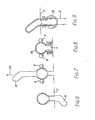
- Figure 1 illustrates hosiery supported on the points of a toe-closing machine,
- Figure 2 illustrates the hosiery removed from the toe-closing machine and held between the jaws of a clamp,
- Figure 3 illustrates the mouth of the hosiery being opened by a spreading device.
- Figure 4 illustrates the invention of a two-part transfer form into the opened mouth of the hosiery,
- Figure 5 illustrates the hosiery supported on the transfer form having been released by the clamp jaws,
- Figures 6 to 9 are views taken at right angles to those of Figures 1 to 5, Figure 6 depicting the hosiery top supported on the transfer form, corresponding essentially to the position shown in Figure 5,
- Figure 7 illustrates more of the hosiery being driven on to the transfer form by drive rollers,
- Figure 8 illustrates the whole of the hosiery supported on the transfer form,
- Figure 9 illustrates a boarding form being inserted into the transfer form to remove it therefrom whilst simultaneously turning the hosiery inside out,
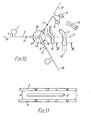
- Figure 10 illustrates the three limbs of the transfer mechanism and their sequential operation between three stations, and
- Figure 11 is a sectional view through the transfer and hosiery forms taken on the line VI-VI of Figure 10.
- In Figure 1, hosiery in the form of a sock or stocking 19, is supported inside out upon the points (not shown) of a toe-
closing machine 21. The toe-closing machine is known per se and forms no part of the invention. The particular toe-closing machine used is known as a Rosso toe-closing machine but other toe-closing machines may be used. The function of the transfer mechanism of the invention is to transfer hosiery automatically from the points of the toe-closing machine onto a hosiery boarding form ready for further processing, typically boarding, examination and packing, ready for sale. - Figure 1 shows therefore the two
jaws 22 of a clamp about to close onto thehosiery 19 at a position below themachine 21. In Figure 2, the clamp jaws have clamped the hosiery adjacent its toe end and been caused to move in two directions, identified by thearrow 24, both radially away from themachine 21 and then downwardly towards a sensing position. The sensing position consists of a photo-electric cell 25 which is actuated when the mouth or top of the hosiery is detected. Actuation of thecell 25 interrupts downward movement ofclamp 22 to leave the hosiery suspended in the position shown in Figure 2. In this position, the mouth end of the hosiery is disposedadjacent pipes 26. Actuation of thecell 25 also initiates the supply of reduced pressure to the pipes. The action of the reduced pressure is to open the mouth of the hosiery ready to receive thespreader fingers 28 of a spreader. - The spreader has four
fingers 28 which lie adjacent one another when the spreader is in a closed condition but which spread radially outwardly when the spreader is opened. Figure 2 shows thespreader fingers 28 in a closed position and ready for insertion, in the direction of the arrow, into the mouth of the hosiery. - In Figure 3, the spreader fingers have been inserted into the hosiery and the spreader opened as indicated by the
arrows 30. A two-part transfer form 1 is illustrated beneath the spreader and ready for insertion in the direction ofarrow 31 between the spreader fingers into the mouth of the hosiery. The two parts of the transferform are each in the form of a wire bent into the general form of the Greek letter omega as may best be seen from Figure 6. Figure 4 shows the transfer form inserted into the mouth of the hosiery. It will be understood that although the transfer form illustrated consists of bent wires, the invention is not limited in this respect since spaced apart members of any suitable configuration may be used. - In Figure 5 the transfer form has moved upwardly in the direction of arrow 32 to strip the hosiery from the
spreader fingers 28. At the same time thejaws 22 of the clamp have opened in thedirection 33 to release thehousing 19 thus allowing it to hang freely carried solely by the transfer form 1. Figure 6 corresponds to the position shown in Figure 5 but shows a view perpendicular to that of Figure 5 to enable the omega shape of transfer form wires 3 to be seen. - At the position illustrated in Figure 7 an
air current 20 has caused thehosiery 19 to be extended to remove tangles and like irregularities. The hosiery is retained upon the form by virtue of its elastic welt which bears against the bulbous underside of the transfer form. A pair ofrollers 8, 9 are then placed in driving engagement with opposed parts of the housing supported upon thetransfer form 30. Therollers 8, 9 drive the leg and toe portions of the hosiery onto the transfer form until the whole length of the hosiery is accommodated upon the form as may be seen in Figure 8, where the leg length of the hosiery is folded as a concertina upon theneck 5 of the omega-shaped wires 3. - Figure 9 shows a flat
hosiery form 2 being inserted into the spacing between the two transfer form wires 3. During this operation, as the housing is being received onto the housing form, it is simultaneously being turned to correct side out. - At the completion of the cycle of operations described above, the hosiery, supported upon the
hosiery form 2 is ready for heat setting in a boarding machine (not shown) followed by inspection and, if satisfactory, for packing. The step of turning of the hosiery correct side out which was previously achieved manually is now achieved automatically. Further, the step of manual loading of the hosiery upon the form is eliminated. - The transfer mechanism is illustrated in its practical form in Figure 10 in which similar reference numerals have been used to identify the same parts as those referred to in Figures 1 to 9. For ease of illustration however, no hosiery is shown in Figure 10.
- The mechanism of Figure 10 consists of a wheel having three tubular limbs which are equi-angularly spaced apart by an
angle 14. The wheel is rotatably mounted at 21 for indexed movement between threestations rod 6 is resiliently mounted, by springs not shown, in each tubular limb to enable eachrod 6 to move, as a piston, in its associated limb. Intermediate the ends of eachrod 6, aroller cam 11 is provided which travels along aguide track 12 betweenstations 17 and 18 for a purpose to be described. A transfer form 1 is fixed to the outer end of eachrod 6 for movement therewith. -
Station 16 corresponds with the positions shown in Figures 5 and 6 where hosiery is initially received upon, and suspended from the transfer form 1. The wheel is then indexed by one movement in a clockwise direction so that the transfer form previously atstation 16 arrives atstation 17.Station 17 corresponds with the positions shown in Figures 7 and 8 inasmuch as the hosiery is extended by anair stream 10 and then driven onto the two wires of the transfer form 1 by therollers 8, 9. Subsequentto loading therollers 8, 9 are moved away from the form to enable the wheel to be further indexed. - As the wheel is indexed once more, the
roller cam 11 enters theguide track 12 so that the transfer form is displaced relative to thelongitudinal axis 13 of theboarding form 2. During this movement, theboarding form 2 strips the hosiery from the transfer form simultaneously turning the hosiery correct side out. Thus, the step betweenstations 17 and 18 corresponds with that shown in Figure 9, so that by the time station 18 is reached, the transfer form is free to receive further hosiery. - In the transfer mechanism as at present, no hosiery handling occurs between the
stations 18 and 16. It will be appreciated however that there is no reason why hosiery could not be loaded at station 18. Further, although the transfer mechanism shown in Figure 10 has a wheel with three limbs, it will be appreciated that any convenient number of limbs may be employed. - The sectional view of Figure 11 shows the two wires 3 of the transfer form 1 spaced apart by a distance A with the
hosiery boarding form 2 within the spacing and serving to strip hosiery from the transfer to the boarding form. - Although the invention has been described with respect to the transfer of hosiery between a toe-closing machine and a hosiery boarding machine it will be apparent that the invention is not limited in this respect since the transfer mechanism of the invention can be used for transferring articles, not necessarily knitted articles, between any two machines.
Claims (13)
Priority Applications (1)
| Application Number | Priority Date | Filing Date | Title |
|---|---|---|---|
| AT85308192T ATE49786T1 (en) | 1984-11-29 | 1985-11-11 | DEVICE AND METHOD FOR CONVEYING HOSEY GOODS. |
Applications Claiming Priority (2)
| Application Number | Priority Date | Filing Date | Title |
|---|---|---|---|
| DE19843443432 DE3443432A1 (en) | 1984-11-29 | 1984-11-29 | METHOD AND DEVICE FOR CHAINING STOCKING MACHINES |
| DE3443432 | 1984-11-29 |
Publications (3)
| Publication Number | Publication Date |
|---|---|
| EP0184340A2 EP0184340A2 (en) | 1986-06-11 |
| EP0184340A3 EP0184340A3 (en) | 1987-11-11 |
| EP0184340B1 true EP0184340B1 (en) | 1990-01-24 |
Family
ID=6251400
Family Applications (1)
| Application Number | Title | Priority Date | Filing Date |
|---|---|---|---|
| EP85308192A Expired - Lifetime EP0184340B1 (en) | 1984-11-29 | 1985-11-11 | Transfer mechanism for and method of transferring hosiery articles |
Country Status (7)
| Country | Link |
|---|---|
| US (1) | US4643340A (en) |
| EP (1) | EP0184340B1 (en) |
| JP (1) | JPS61258067A (en) |
| AT (1) | ATE49786T1 (en) |
| CS (1) | CS269976B2 (en) |
| DE (2) | DE3443432A1 (en) |
| GB (1) | GB2168089B (en) |
Families Citing this family (18)
| Publication number | Priority date | Publication date | Assignee | Title |
|---|---|---|---|---|
| GB8621957D0 (en) * | 1986-09-11 | 1986-10-15 | Detexomat Machinery Ltd | Pantihose packaging |
| US5040475A (en) * | 1989-01-28 | 1991-08-20 | Sara Lee Corporation | Material handling system |
| JPH0381396U (en) * | 1989-12-11 | 1991-08-20 | ||
| JPH04100284U (en) * | 1991-02-04 | 1992-08-31 | ||
| US5165355A (en) * | 1991-03-26 | 1992-11-24 | Sara Lee Corporation | Method and apparatus for handling hosiery blanks |
| IT1258180B (en) * | 1992-08-05 | 1996-02-20 | Solis Srl | METHOD FOR THE TRANSFER OF A TIGHTS FROM A SEWING MACHINE TO A STITCHING MACHINE AND DEVICE FOR ITS IMPLEMENTATION |
| IT1265836B1 (en) * | 1993-02-09 | 1996-12-12 | Solis Srl | METHOD AND DEVICE FOR AUTOMATICALLY RELEASING A TUBULAR KNITTED ARTICLE INVESTED ON A FORM OF SUPPORT. |
| US5507421A (en) * | 1993-12-06 | 1996-04-16 | Keeton; Herbert | Turn and cut machine for reverse-folding tubular textile material and methods of operation |
| GB9402684D0 (en) * | 1994-02-11 | 1994-04-06 | Detexomat Machinery Ltd | A hosiery line closer and loader assembly |
| US5511501A (en) * | 1994-04-05 | 1996-04-30 | Monarch Knitting Machinery Corporation | Method and apparatus for handling flexible objects |
| US5544603A (en) * | 1994-04-05 | 1996-08-13 | Monarch Knitting Machinery Corporation | Apparatus for handling flexible objects |
| GB9507510D0 (en) * | 1995-04-11 | 1995-05-31 | Detexomat Machinery Ltd | Method & apparatus for manipulating a length of flexible material |
| DE69835907T2 (en) * | 1997-05-13 | 2007-04-19 | Threadbear, L.L.C. | Device for positioning socks for automatic machines for shaping socks |
| US6334547B1 (en) | 1997-07-19 | 2002-01-01 | Detexomat Machinery Limited | Method and apparatus for manipulating a length of flexible material |
| US7044071B2 (en) * | 2003-01-24 | 2006-05-16 | B.B. & S Knitting Consultants | Apparatus and method for automatically orienting hosiery articles for closing toe ends thereof |
| ITFI20030059A1 (en) * | 2003-03-07 | 2004-09-08 | Matec Spa | METHOD AND DEVICE FOR LOADING MANUFACTURERS SUCH AS SOCKS, |
| US20090038520A1 (en) * | 2004-04-16 | 2009-02-12 | Golden Lady Company S.P.A. | Machine for handling tubular knitted articles, such as socks or the like |
| US10035169B2 (en) | 2015-05-21 | 2018-07-31 | Nike, Inc. | Method and apparatus for retaining and transferring an article |
Family Cites Families (13)
| Publication number | Priority date | Publication date | Assignee | Title |
|---|---|---|---|---|
| US2286059A (en) * | 1940-12-17 | 1942-06-09 | Isidor Gerber | Machine for turning and pressing gloves |
| FR1395844A (en) * | 1964-03-06 | 1965-04-16 | Heliot Maurice Ets | Tubular article turning machine |
| US3520262A (en) * | 1967-08-23 | 1970-07-14 | Chadbourn Gotham Inc | Method and apparatus for closing stocking toes and putting stockings on boarding forms for processing |
| DD94977A1 (en) * | 1972-04-10 | 1973-01-12 | ||
| JPS52152360A (en) * | 1976-06-11 | 1977-12-17 | Takatori Kikai Seisakusho Kk | Method and device for automatically sewing rectilinearly seamless stocking toe by stationary sewing machine |
| DE7710581U1 (en) * | 1977-04-02 | 1977-09-08 | Dbm Italo Della Bella Gmbh U. Co Kg, 6501 Woerrstadt | Device for turning knitted or crocheted articles such as stockings on processing machines, such as linking machines or the like |
| IT1069950B (en) * | 1979-01-09 | 1985-03-25 | Solis Srl | METHOD FOR APPLYING AN ANCHOR TO TUBULAR ARTICLES SUCH AS LADIES 'SOCKS AND MACHINE TO IMPLEMENT THE METHOD |
| US4223816A (en) * | 1979-02-05 | 1980-09-23 | Surratt Hosiery Mill, Inc. | Hosiery cuff forming apparatus |
| US4487546A (en) * | 1981-08-05 | 1984-12-11 | Savio & C. S.P.A. | Device for transferring tubular fabrics from support hangers to a rigid body and inverting the fabric |
| IT1192498B (en) * | 1982-08-30 | 1988-04-13 | Solis Srl | PERFECTED DEVICE FOR THE TRANSFER OF FOOTWEAR ITEMS AND SIMILAR FROM AN INSPECTION FORM TO AN IRONING FORM AND FOR EQUIVALENT USE |
| IT1192943B (en) * | 1982-12-30 | 1988-05-26 | Solis Srl | TRANSFER AND INITIAL FOLDING DEVICE OF A SOCK OR TIGHTS, FOR THE SUBSEQUENT PACKAGING |
| IT1160526B (en) * | 1983-03-09 | 1987-03-11 | Fadis Spa | MACHINE FOR REVERSING SOCKS WITH COUNTER-ROTATING ROLLERS WITH AUTOMATIC FEEDING |
| IT1205383B (en) * | 1983-04-11 | 1989-03-15 | Rosso Ind Spa | STOCKING DEVICE |
-
1984
- 1984-11-29 DE DE19843443432 patent/DE3443432A1/en not_active Withdrawn
-
1985
- 1985-11-11 AT AT85308192T patent/ATE49786T1/en not_active IP Right Cessation
- 1985-11-11 EP EP85308192A patent/EP0184340B1/en not_active Expired - Lifetime
- 1985-11-11 DE DE8585308192T patent/DE3575586D1/en not_active Expired - Fee Related
- 1985-11-11 GB GB08527754A patent/GB2168089B/en not_active Expired
- 1985-11-20 US US06/800,047 patent/US4643340A/en not_active Expired - Fee Related
- 1985-11-25 CS CS858467A patent/CS269976B2/en unknown
- 1985-11-28 JP JP60268257A patent/JPS61258067A/en active Pending
Also Published As
| Publication number | Publication date |
|---|---|
| GB2168089A (en) | 1986-06-11 |
| GB2168089B (en) | 1988-10-26 |
| EP0184340A3 (en) | 1987-11-11 |
| CS846785A2 (en) | 1987-08-13 |
| US4643340A (en) | 1987-02-17 |
| DE3575586D1 (en) | 1990-03-01 |
| JPS61258067A (en) | 1986-11-15 |
| EP0184340A2 (en) | 1986-06-11 |
| ATE49786T1 (en) | 1990-02-15 |
| GB8527754D0 (en) | 1985-12-18 |
| DE3443432A1 (en) | 1986-05-28 |
| CS269976B2 (en) | 1990-05-14 |
Similar Documents
| Publication | Publication Date | Title |
|---|---|---|
| EP0184340B1 (en) | Transfer mechanism for and method of transferring hosiery articles | |
| JP2580088B2 (en) | Automatic forming, manufacturing apparatus and forming method of pantyhose | |
| US4649838A (en) | Process and machine for sewing the toes of pantyhoses with feed from a machine for forming pantyhoses and with ejection suitable for a subsequent automated transfer of the product | |
| US4539924A (en) | Loading system for a toe closing assembly | |
| US4564133A (en) | Apparatus and method for rapid loading of pantyhose onto a stocking finishing medium | |
| US20110158785A1 (en) | Apparatus for automatic transfer of textile articles from a linking machine to a boarding machine | |
| US5511501A (en) | Method and apparatus for handling flexible objects | |
| GB2058002A (en) | Apparatus for folding tubular garment pieces | |
| US5005691A (en) | Apparatus for suspending garments on hangers | |
| US3902300A (en) | Flat folding and packaging apparatus and method | |
| EP0878573B1 (en) | Sock boarding apparatus | |
| US3464602A (en) | Shirt unloader and delivery apparatus | |
| US4491255A (en) | Collapsible hosiery form | |
| US3811607A (en) | Hosiery form | |
| US3806009A (en) | Method and apparatus for handling hosiery | |
| EP1243682A2 (en) | Method and apparatus for longitudinal orientation of hosiery articles | |
| CA1316406C (en) | Method and machine for the automatic transfer of pantyhose and similar articles from a toe-sewing machine to a drawing machine | |
| DE60121741D1 (en) | METHOD AND DEVICE FOR OPENING, ORIENTING AND TIGHTENING SOCKS ON SHAPES | |
| EP0254463B1 (en) | Hosiery manufacture and packaging | |
| US2954906A (en) | Automatic handling equipment | |
| US3768226A (en) | Flat folding & stacking method and apparatus | |
| US4440329A (en) | Apparatus for unloading hosiery machinery | |
| US5544603A (en) | Apparatus for handling flexible objects | |
| JPH0711569A (en) | Method and apparatus for arranging two tubular articles at specified position on corresponding substrate | |
| US4102727A (en) | Method for closing end portions of tubular fabric articles |
Legal Events
| Date | Code | Title | Description |
|---|---|---|---|
| PUAI | Public reference made under article 153(3) epc to a published international application that has entered the european phase |
Free format text: ORIGINAL CODE: 0009012 |
|
| AK | Designated contracting states |
Kind code of ref document: A2 Designated state(s): AT BE CH DE FR IT LI LU NL SE |
|
| PUAL | Search report despatched |
Free format text: ORIGINAL CODE: 0009013 |
|
| AK | Designated contracting states |
Kind code of ref document: A3 Designated state(s): AT BE CH DE FR IT LI LU NL SE |
|
| 17P | Request for examination filed |
Effective date: 19871106 |
|
| 17Q | First examination report despatched |
Effective date: 19881212 |
|
| GRAA | (expected) grant |
Free format text: ORIGINAL CODE: 0009210 |
|
| AK | Designated contracting states |
Kind code of ref document: B1 Designated state(s): AT BE CH DE FR IT LI LU NL SE |
|
| ITF | It: translation for a ep patent filed | ||
| REF | Corresponds to: |
Ref document number: 49786 Country of ref document: AT Date of ref document: 19900215 Kind code of ref document: T |
|
| REF | Corresponds to: |
Ref document number: 3575586 Country of ref document: DE Date of ref document: 19900301 |
|
| ET | Fr: translation filed | ||
| PG25 | Lapsed in a contracting state [announced via postgrant information from national office to epo] |
Ref country code: AT Effective date: 19901111 |
|
| PLBE | No opposition filed within time limit |
Free format text: ORIGINAL CODE: 0009261 |
|
| STAA | Information on the status of an ep patent application or granted ep patent |
Free format text: STATUS: NO OPPOSITION FILED WITHIN TIME LIMIT |
|
| PGFP | Annual fee paid to national office [announced via postgrant information from national office to epo] |
Ref country code: SE Payment date: 19901129 Year of fee payment: 6 |
|
| PG25 | Lapsed in a contracting state [announced via postgrant information from national office to epo] |
Ref country code: LU Free format text: LAPSE BECAUSE OF NON-PAYMENT OF DUE FEES Effective date: 19901130 Ref country code: LI Effective date: 19901130 Ref country code: CH Effective date: 19901130 Ref country code: BE Effective date: 19901130 |
|
| 26N | No opposition filed | ||
| BERE | Be: lapsed |
Owner name: PEX (HOLDINGS) LTD Effective date: 19901130 |
|
| PG25 | Lapsed in a contracting state [announced via postgrant information from national office to epo] |
Ref country code: NL Effective date: 19910601 |
|
| NLV4 | Nl: lapsed or anulled due to non-payment of the annual fee | ||
| PG25 | Lapsed in a contracting state [announced via postgrant information from national office to epo] |
Ref country code: FR Effective date: 19910731 |
|
| REG | Reference to a national code |
Ref country code: CH Ref legal event code: PL |
|
| PG25 | Lapsed in a contracting state [announced via postgrant information from national office to epo] |
Ref country code: DE Effective date: 19910801 |
|
| REG | Reference to a national code |
Ref country code: FR Ref legal event code: ST |
|
| PG25 | Lapsed in a contracting state [announced via postgrant information from national office to epo] |
Ref country code: SE Effective date: 19911112 |
|
| EUG | Se: european patent has lapsed |
Ref document number: 85308192.5 Effective date: 19920604 |